Control the simulation time to align the time system
Good so maybe it's blindingly obvious or just simply a ridiculous question but here goes:
I run a dll that I produced from a .mdl file. My goal (among others!) is to get the dynamic response of the exact model of 'real world' calendar (date system). The tuning for the appearance of the control of this model is based on the duration of simulation with produced in simulink and so it is desirable for me to define the duration of the simulation to run when the system.
The problem I have, if you open the workspace and produce a template control, the simulation shown time is much faster than the time system.
For example, one iteration of the model takes a fraction of a second. What I imagine happens, it is immediately restart (and progress of a time step). I guess I want the model to wait until it is in harmony with the system time before iterate again.
Is there a way to solve this problem, and do anyone know if this problem will be resolved in Simulink or Veristand 2009.
Any information would be appeciated, my trawl of the help files OR have not really answered the questions yet good
Thank you
James
The models are running in sync with the rest of the system. Unless you specify a decimation factor for your different model of 1 for each tick of the primary control loop your model put once, too. The difference between the model and system duration that you see is due to the fact that the model time is based on its time not Delta T compiled, not any of the wall clock time. Every time that the model is Ticktock, it adds its own Delta T to its operation time string.
The time channel system is based on the Delta T of the primary control loop. Thus, it corresponds with the rate you specified the system to run at. If these Delta Ts are the same, are aligned at the same time. If you want the time to model to match an actual wall clock time, you can adjust the flow of the loop of the primary control loop to match the Delta T, or adjust the factor of the decimation of the model so that it gets only checked once for every N the primary control loop iterations.
Tags: NI Products
Similar Questions
-
With the help of control and simulation module; e to get the time the MISO model Manager
Hello
Please can someone show me how to find the response time of the system below using the module control and simulation?
(y (k) - 1,7407 y (k-1) + 0.6236y (k-2) + 0.1782y (k-3)) =-0.0932 u(k-1) + e (k)
where there is out, u came and e is a white noise.
I tried to enter the CD construct MIMO model, then connect it to CD response time. * s vi.
But what I really need to enter the model coeffs every time? and I still don't see the answer!
Help, please...
Kind regards
ruser
Hello
you have the correct image... I used the Toolbox ID sys (Assistant)... to estimate the system model...
and I tried all week last get the model of my system in labview for use the control on this module.
Alhamdulillah...
I ended up doing... I saved the template to a file from the Toolbox id sys... (my model is in discrete form) then I loaded it in labview using load file pattern...
so now I in labview...
now for control parts...
 ..
..Thank you again...
ruser.
-
SMU-6556 - how to control the rise in digital lines (hsdio) time
Hello
Is it possible to control the rise in digital lines SMU-6556 time?
Even in a low frequency 10 kHz signal rise time is 2ns.
TKS,
Hello engfpe,
The SMU-6556 is a 50 Ohm system, which means that the output is source series finished to be 50 Ohms and all our cables and accessories are 50 Ohms. With this configuration, regardless of the flow of data, you should have a clean edge up or down, regardless of the data rate. The quality of the production (edge up or down) on your device is related to the adaptation of impedance of your cables.
The SMU-6556 cannot adjust the speed of scanning by itself. However, you can insert simple passive components to do it for you. I have attached below the images. The first is a diagram showing a way to slow down the edge. The second is the a waveform simulation showing the rate of original edge before it slows down and the edge of idle. This simulation is not the SMU-6556 but rather a generic digital output for concept. In the schema that R1 is set on 34 Ohms because U1.8 has the 16 additional Ohms on the inside. TL1 is the output of 50 ohms simulating the cable on the SMU-6556. R2, R3, and C1 are components, you can insert after the SMU-6556 twist before moving your device/cable. In this configuration from cable to your device is TL2 which is also 50 ohm, but it could be another impedance in which case you would change R3 to match.
You can see in the attached images, you can slow down significantly the edge with this configuration by altering the C1. I hope this helps.
-
Control the time times of high and low of trains of pulses in C++
Dear team of support of National Instruments,
Here's what I have so far:
I was able to generate the number of pulses (a pulse = a rising edge and front descending one) that the user has indicated via the GUI I created in Visual C++ 2008.
I use DAQmx 8.6.
I use the DigitalSingleChanWriter (hopefully, that's what it's called).
I use for the synchronization of the sample, on request. I tried to use all other types of calendar but I always get a DAQException run the error that says I can use only OnDemand calendar.
OK, so here's the problem:
I have a USB-6008-6009 card connected to an oscilloscope. I know that the connection is correct, otherwise nothing would appear. However, if I send say... 6 impulses, the delay between the first rising edge and the first falling edge is dramatically different and then the second and the third. If I return my samples, I get an assortment of new and totally random times. So finally, my question is "Is there a way to control the time of a great time and a bit of time?"
I use a Compaq 2003 lap top, what is worthy of the rubbish heap. I'm not to blame on this right away as problems that will not solve the problem at hand. Although I understand if it's actually the problem for random times, but I would still have no way to control the time themselves.
I hope that I don't have drug it too long, but I decided that distribute information on would be better then just a few tid bits.
Thank you for support, that you can offer,
Daniel
OK, so I just returned from the lab, and this is what I got:
I was able to control the time at the time of the high and low by using the "WriteSingleSamplePort" of the DigitalSingleChanWriter method.
I put it in a loop that repeated many times that the user wanted impulses.
At the beginning of the loop, I used a delay function that I wrote and delayed for a time given and then a pulse with a value of 255 and then delayed again and a pulse with a value of 0. And then restarted the loop.
In the end, it works.
Of course, I have another question. I kept reducing the amount of time between two pulses (1 s, .5s, .2us and so on). However, once I have diminished the time of secondes.01 or a millisecond, the pulses on the arrested oscilliscope becomes smaller. It seems that past 1 millisecond Board USB-6008/6009 is unable to deal with the exigencies of the moment. Or else the computer trash part on that I cannot deal with the exigencies of the moment. But I believe that the Council is not at fault because it was designed for this exact sort of thing, could you tell me if there is no limitation to the Commission which prevent production of pulses in or within a period of 1 millisecond. Thank you very much.
Thanks for all the help,
Daniel
P.S. I'll stop you buggin with big messages that I promise you.
P.P.S. If someone wants to see my source code for their own project, I'd be more than willing to share. Please email me or leave a message here.
-
CHKDSK finishes control, complete control, the computer tries to start and goes back to CHKDSK everytime, it means my hard drive crashed? and if so, can I just replace the hard drive and then have my technical support help reload my data?
Hi Karen,.
· Since when are you facing this problem?
You can check if this article helps.
-
Hi Experts,
We currently use scripts UCCX 7.0 with opening and closing hours of CSQ controlled via defined under the time of day in the script.
I would like to know if it is possible to control the opening and the closing time of a script based on an agent is connected or not?
So basically, the office is deemed open when an agent is connected and deemed closed when there is no connected agents regardless of the time.
If possible, can you kindly point me in the right sense of how implement this corresponds to the script.
Kind regards
THERE.
Hello
Sure... in short:
-Use a step "to obtain the statistical report" to see how many officers is connected, or "ready" (your choice) and store that in an int variable
-If this > 0 then 'goto' your behavior variable open.
-If it is 0 or - 1, then goto closed.
Aaron
-
Control the user wait times in the workspace
No way to control the time-out in the workspace. users are complaing that 15 minutes is too short.For version 11 have a read of:-http://download.oracle.com/docs/cd/E12825_01/epm.111/bpmui_admin/ch02s03s01s01.html
See you soon
John
http://John-Goodwin.blogspot.com/ -
Function of memory in the loop control and Simulation - problem of the ODE Solver
Hello
I'm correctly using the control loop & simulation to simulate the behavior of what is essentially a shock absorber-spring-mass system. In the process of change in time (dt) is used to integrate an arbitrary value. I use a rack depending on memory to store the time, to calculate the change of time (dt).
The simulation is quite complex, because of the precision required, not all the ODE solvers can all support. Currently I use the Adams-Moulton method, this works very well for the simulation. However, it cannot detect the change in time, the change is constantly zero. This problem has auto market by using an another ODE Solver, but then the simulation has been messed up instead (even when I listen to the step sizes and tolerances). So I'm pretty confident that Adams-Moulton is one of solver ODE best suited to the problem at hand.
Is there another way to store the previous hour and use it calculate lag, that the use of the memory function? Everyone knows about these problems before?
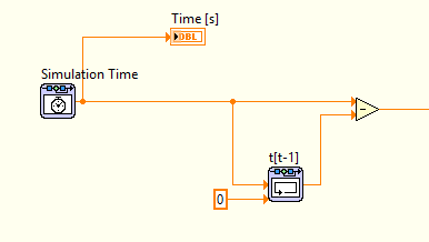
I did a lot of research of error using the probe, but I'm sure that there is a problem with the ODE Solver and memory function. See the image below, showing basic how is calculated the change in time.
I'm pretty new to LabVIEW, so if there is something else I missed I would be happy to hear it.
PS! I set the tolerance minimum step of size/relative and absolute for the Adams-Moulton to simulate the behavior of the system properly.
Problem solved!
It turns out that the ODE Solver has struggled because of two "table 2D find" used functions. This was created for the interpolation/extrapolation, which caused a problem constantly and the ODE Solver could not resolve correctly, so the functions of memory doesn't work does not correctly or the other.
By increasing the table manually, I could use closest method instead, with also good results as interpolation.
-
How to get the Subvi (the virtual path is in .exe) reference in Run Time System
Hello world
The problem is how to get the reference of the Sub - VI in run time system, when the Subvi is in .exe after construction.
More details:
Top of page vi called the Subvi dynamically, so that the Subvi is always included, and the source object is the application.exe.
After the above configuration, the Sub - VI will be the application.exe. For example, the path of Subvi est...\application.exe\SubVI.vi
So, how to get the reference of the Subvi in Run Time System?
I can't do it when you use 'open reference VI' with le...\application.exe\SubVI.vi path in the run time system.
In fact, I can create a file to include the Subvi, rather than build the Subvi in application.exe, then I can get the convenintly reference. But this isn't my favourate average.
Thank you
chenyin
That is the problem. Call a Subvi dynamic means users could change, but it is also very attractive.
The dynamic call should be used in a user control, but some parade can avoid problems.
It depends on why you use dynamic calls...-online 2 main ways:
-Dynamic call are used to maintain a scalable framework for the code without acting on the executable file-online a single VI distribution managed by the administrator/developer
-Dynamic call are used to provide a collection of "external" characteristic that could be enriched by the administrator/developer. For example, you provide your customers a set of selectable custom signal filters in the executable.
In 2 cases, you are only able to assess the skills of the users to know if there is a risk of damage, if there is a change.
So to stay only master a parade might be to provide dynamic VI without a schema, but with the problem of maintenance, since no in-place editing and more attention to manage distribution.
Another way is to hide the actual distribution to user-online call dynamic VI but it without name as *.vi but others (a repellent name as system of OS name
 ) or simply without extension in order to attract not user... but that's debatable...
Another more difficult but more secure method is to create a consistency check before your routine (version, user, modified date,...)
-
I get a message saying that I don't have privileges to change the time system.
I use Windows XP Professional as an administrator. The message is that I have enough privileges to change the time system?
original title: time systemAs you probably understand, setting is translucent because your IT Department at work has controlled this configuration in the field (which is why I have inserted the caveat "unless the domain policy changed that"). When you exit your laptop from work to home, the domain policies remain in place. If you do not have the administrative rights on the computer, you should always be able to change the policy by using KB266280 of my previous post... but as soon as plug you it into the network of your domain to work, the policy will return.
HTH,
JW -
You can see how many times a Mac fell in the OSX system?
Anyone know if you can see how many times a Mac fell in the OSX system?
I know that you can see, but I don't know.
I already checked system information etc.
Thank you!
Kind regards
Rajesh
If you mean physically not fallen there is no information.
-
Since the last system upgraded my menu bar top with wifi and time, date etc etc is hidden unless I have sulk my cursor on it. Same thing with apps from shingles. How can I restore it is always there? bar menus hidden-how do I restore?
SystemPreferences-> Dock: automatically hide / show Dock
SystemPreferences-> general: automatically hide / show menu bar
-
42HL833B - how to change the time system of the Australia
I have a Toshiba 42HL833B I brought back with me in Australia from the United Kingdom.
Everything works OK, another time system shows always the time of the United Kingdom.
The Australia does not come as an option in the configuration of the country so I chose 'other '.It doesn't seem to be anywhere where you can change the duration.
Is it possible to change the time manually somehow?I put t know if you s manuals with you, but you can download it here.
Maybe you can find info how to proceed. -
Apple Extreme, Time Capsule and Express on the same system, what is the best way to set it up so that all devices smoothly from one end of the House to another?
I'm going to assume that you plan to have wireless devices.
Let's say that the Capsule is your "main" router If this is the case, then it must be located in the House, so that the distance between the time Capsule is the same for the outside walls of the House.
Then, on the 'left' side of the House, looking for an airport to midway between the Capsule and time of the outer wall of the House. Do the same thing the 'right' side of the House.
In other words, each of the two airports that "extend" the wireless signal are located at equal distance from the Capsule of time... but they are in opposite ends of the House.
If you intend to interconnect all the airports and Time Capsule using a permanent, Ethernet wired... which by far is the 'best' way to put in place a network in terms of performance and reliability... then you can locate one of the devices anywhere you want.
-
by using labview co-simulation, how to control the PWM market factor in multisim
I am new to the use of Multisim with LabVIEW using co-simulation. I would like to ask if there is a PWM component in Multisim, which can have its cycle have to be controlled using LabVIEW? I have an algorithm in LabVIEW that returns the duty cycle values between 0 and 1, representing the percentage of duty cycle.
How can I control the PWM market factor in Multisim using LabVIEW co-simulation?
Thank you very much
SPECTRUM
Hi spectrum,
In Multisim, find items based on functionality, there are some PWM models in the database. Take a look at this knowledge base if you don't know how to search for parts:
http://digital.NI.com/public.nsf/allkb/7309A5CABC677296862577ED006EC99E
Also, take a look at this knowledge base:
http://digital.NI.com/public.nsf/allkb/EF391C48CF71AE4F862571B900644F84
This article shows you how you can get Mutlisim and LabVIEW to co-simiualte:
http://www.NI.com/white-paper/13663/en
I hope this helps
Maybe you are looking for
-
My 5 years old Satellite Pro P300-19 q has developed all of a sudden a fault
Without realizing, I posted the message below on the Forum we Toshiba: Hello My laptop which is 5 years old and has worked without any problems, has suddenly developed a fault I don't seem to be able to untangle. It starts ok and gets on the screen "
-
HP pavilion g6: my laptop to not start.
My laptop won't start. Lock shift of this pc is flashing. What should I do?
-
1800 to ASA VPN problem, fail to Phase 2
Hello I have a series of 1800 running IOS 12.4 (6) T11 and an ASA 5505 8.2 I try to connect using a lan lan tunnel 2 running. 1800: WAN a.b.c.141 LAN 192.168.0.0/24 ASA5505: WAN x.y.z.125 LAN 10-180.3.0/24 The 1800s also has pptp, 172.16.99.0/24 netw
-
Why "in grayed unnumbered markers" when using automate to sequence
On Mac OS X El Capitan. Premiere Pro cc 2015.4.It has always worked for me before. I tried opening and closing. Any sugguestions?
-
Create a field in the rules file
Hi allI hope that you all made great.I had an obligation to create a field at the entrance to souce as followsinput source will be 7 characters and must create a field by taking the last three characters and last clandestine figure into a double-digi