convert 1 d undulating 2D signals
My problem is that I want to write a graph of daqmx writing that will be read by daqmx read. The way I have it now is a form of wave 1 d. My code is attached with the post. My goal is to create a waveform of 8 channels of all zeros, then select what channel I want to choose to apply a waveform. If I choose channel 1 and 3. These two will be affected by a sine wave, and the rest will be a waveform of all zeros.
I mean if I have a waveform of all zeros and I feed him to the subset of spare board (upper receiver) and I have an actall waveform and feed to the subset of table to replace (low sink). I used a 1 d numerical control or index of the ListBox in the new array. If my index value is 1 and 3. This means that row 1 and 3 that have been all zeros will be replaced by the waveform (sine wave) and the remaining lines (0, 2, 4, 5, 6, 7) will always be a waveform of all zeros.
But what to display, since my waveform is a 1 d array, I can't show more than one waveform on the chart. How can code this in a way where I get a table 2D waveform for each channel. I know I can't write a waveform daqmx writing 2D array, but what can I do if I choose a multiple waveform to display. At the moment each chart are displayed one after the other. seet photo
Thanks in advance. See attached picture
Note attachments removed by the request of the user of the admin-
Tags: NI Software
Similar Questions
-
How to convert an analog signal into digital signal
Hello
How to convert an analog signal into digital signal, such that each sample of the analogue signal corresponding to 1.2V will be represented as '1' digital signal and other samples of the analog signal (which are not 1.2V) will be represented (converted) ' 0' in the digital signal.
And how to view the wavefroms or graphical indicators signals.
Thank you.
If you have 1000 samples and you want to convert to digital, you get 1000 digital values. Attached, that's what I mean.
-
Signal (PAL 60) record with the Qosmio G40 Line In (Capture) Option
I'm in Australia - and I have a lot of NTSC video tapes I want to MPEG...
These bands play very well on all the TVs/LCD TV in the House.
Qosmio G40 seems to have problems with PAL 60 signal that sends my VHS player...
My VHS/DVD from Toshiba drive is to convert NTSC to PAL 60 signal - as this VHS player bought in Australia - this seems to be the Australian standard bought a VHS/DVD player.
There is no option on the VHS player to the NTSC signal... I tried another VHS player - and it gives me the same output PAL 60, this player also could leave the NTSC signal...
So I wonder if the Qosmio G40 is able to record the signal PAL 60 - maybe I'm missing a setting somewhere...
I use Ulead movie maker software, which is supplied with the machine... but I don't see any options on the support PAL 60...
Maybe the TV card installed in the machine does not support PAL 60 - I can't find any info about this...Maybe I need to use a software of different capture which will support PAL 60 options...
Or maybe I just buy a VHS of America drive, and qosmio q40 will capture the NTSC image very well... (I already have a few products from 110V at home)Any thoughts?
Hello
I'm not sure if this is possible, but you can check the BIOS settings, if there is an option that would allows you to change settings of NTCS/PAL.
Check it out
-
BlackBerry smartphones CONVERT BROADBAND WIFI
BACK ANY ONE NOW HOW TO CONVERT HIGH SPEED BB WIFI SIGNAL? OR HOW FILL BB WITH PC AND DIGITAL PHONE WORKING WITH INTERNET?
Thank you
ALEJANDRO
CradlePoint makes a router you can connect your BB in and create a WiFi hotspot:
-
Third monitor does not work with Eyefinity more
I am trying to run 3 monitors on my ATI HD 5770
I have two computers that, for years, have worked with several thin monitors... until very recently. Through all my updates to the OS, they continued to work. I don't remember exactly at what time each card has ceased to power its third monitor. Each of my "third monitors" would come on periodically until they all finally stopped.
All monitors are working fine as I juggle the cables and adapters each refreshes and lights up but not all at the same time.
Here's what I have available for troubleshooting.
I have two Mac Pros below. (OS 10.11.6) on one and (OS 10.7.5) on the other.
Each tower has (2) 5770 cards installed that each have a DVI and 2 mini ports.
So I have a total of (4) cards and is starting the new one that I got on ebay last week.
I have LG E2350V 23 "monitors (6) and (3) 22" ACER monitors
All my cables are active and I have several active adapters
I just bought some passive extra and many very active adapters to the experience and trouble shooting with.
Thanks in advance for the help and time!
DisplayPort and its variant electrically identical but small size Mini DisplayPort and the implementation which is a subset of Thunderbolt, any differential use (push-pull) of signals pilot very low voltage. They are MORE immune to noise than old methods because the signal is encoded on the difference between the two signals, not a single signal referenced to a "everybody" on the ground. If possible, you must connect all screens with DisplayPort [full-size] or Mini DisplayPort. These put a lot less load on your system.
When you convert this very low level signal to an "inherited" display, the map is short of ability to directly signal levels in the car high enough to be recognized after connection of TWO monitors legacy of any kind. If you choose to use a DVI or HDMI port supplied directly, that still counts as one of your two "free" conversions (It is also possible that a very fussy display is moved even earlier).
All display "legacy" beyond the first two requires ACTIVE description adapters. Adapters ASSETS contain re-drivers of signal and are therefore more expensive than ordinary adapters. Typical prices are of the order of $ 40, but competition has lowered some prices slightly. Mini DisplayPort has a descendant-comparability mode requested by the regular cards, who can get to produce a Single-Link DVI signal to up to 1920 wide, but a regular adapter not pushed the signal levels.
The Apple Mini DisplayPort to DVI Dual-Link, which is used for DVI displays wider width of 1920, is more complex and expensive and requires extra power beyond all signal re-pilots. This power is usually taken on a tail of pig USB, USB data are generally not used by the adapter, so a different USB power source can be overridden.
-
IPad Air to TV HDMI cable connection problem
I can watch the movie using YouTube even he inserted ads several times during playback in iPad Air. But when I connect iPad Air to the TV cable HDMI, the TV does not work after second played advertising time, the screen went black. I can continue to watch only, disconnect and reconnect the cable. How can I solve it? The iOS is 9.3.1.
Hello HSIAO CHUN.
If you experience problems connecting to your iPad Air to your TV via a digital AV adapter from Apple, the information described below can help to restore all the features to your configuration.
If an application is no video display or read audio data
The app is not compatible with the adapter. Check compatibility on the information page of the application in the App Store or contact the developer.
If an alert says a HDCP compatible device
Your content is not compatible with the adapter. Movies, series TV and video streaming applications require High-Bandwidth Digital Content Protection (HDCP). If you try to play these movies, shows and streaming videos using a connection digital non-HDCP - as the Apple VGA adapter - one alert will ask you for a HDCP compatible device.
If you need help with other issues
- Disconnect, then reconnect your adapter on your iPhone, iPad or iPod touch and your TV, monitor or projector.
- Make sure that your VGA or HDMI cable works, given that the issue could be with the cable.
- Remove all cables extension VGA or HDMI or converters. Accessories that convert a VGA or HDMI signals to different video formats (DVI, Composite, Component) are not compatible.
- Make sure you have the latest version of iOS.
- Contact Apple support.
On AV adapters digital Apple for iPhone, iPad and iPod touch
https://support.Apple.com/en-us/HT202044All my best.
-
How to connect Equium A100-306 to HDTV?
Hello
I was wondering if it was possible to connect my Equium A100-306 to my HDTV using a VGA cable component? The laptop has the chipset intel 945g.
Thank you.
Hello
You cannot convert only a RGB (VGA) signal to component (Y-Pr-Pb), since you will need a converter that transforms the signal vga to this component.
Which means that you also a converter for cable that could be very expensive. But if you've got components that you should be able to display an image on a device that has entry components. Don t think you will be able to run the HD-ready or full HD on a HD TV, since a HD signal requires an HD port on your computer and a disk hard taking supported system with better graphics chip and then a chipset intel.
Welcome them
-
What is the maximum voltage of the members of the PXI 4461 gain 20 dB?
I use a Board, PXI-4461 sample sine wave with an amplitude of slightly greater than 1 V peak (1.0005 V). The gain of the Board of Directors is set at 20 dB and the input range should be from-1 to + 1 V V! That's why I expect that see a saturation of the converter ADC when the input signal is greater than 1 V. However, I do not respect this saturation of the output value, and I don't understand why?
Could someone explain that to me?
Thank you in advance.
Frédéric
Hello Frederic,.
almost all NI DAQ devices I know has a small "margin of safety" in each range given acquisition (usually about 0.5-2%), allowing you to accurately measure the voltage specified limit.
The exact width of this margin is not explicitly mentioned, probably to prevent users to use this line on a regular basis.
In short: there's a small safety margin, but do not count on it when designing measurement applications. ;-)
Best regards
Sebastian -
How can I create delays for many digital outputs?
I use a PXI 6537 DAQ card to produce four digital signals for each starting at a different time. In order to create this delay the appropriate number of '0' have been placed at the front of the boolean table before converting it into a digital signal. It works by creating the delay, however using this process, the delay may be discrete increments equal to 1/╔chantillonnage and my card can be up to 50 MHz, this means that I can produce only delays 20ns increments (check my calculations). For my application, I need to be able to control the time until the second nano. Delays will usually be more than 20 ns, but less than 40ns. I tried to use the entry 'to' the 'build waveform.vi' but it doesn't seem to do anything to manipulate the data. The sub VI used to create the waveform is attached. Sending the data isn't a problem. Thanks in adavnce for any suggestion.
JS
Hi JS.
The 6537 allow placement of subsample edge on its i/o lines. The best you can do is unique (like you the noticed) examples of resolution (20 ns @ 50 MHz).
Have you looked at the SMU-6545? It is a 200 MHz Board, which means that you will get 5 placement ns, as WELL as data delay feature which lets you place your samples with ~ 150ps resolution compared to the output clock.
Are you having to change the location of a signal in the clock period each cycle? Or is the position fixed by reference to the clock, but must be placed exactly?
Thank you
Keith Shapiro
National Instruments R & D
-
Hello
I'm looking for different options for controlling an electronic valve. Order entry is the electronic voltage between 0-10 Volt signal and I need accuracy of 0.1 Volts. Is it possible to get a digital output on the computer (such as USB) and convert it into an analog signal within the corresponding range through the use of the products OR commercially available?
Best,
Sertan.
Hi Sertan,
If you are looking for a specific product range, it seems that our M-series products will provide your desired features: USB, +/-10V output analog and a higher accuracy you need. Nice day!
-
HAVE high sampling frequency of trigger
Dear community
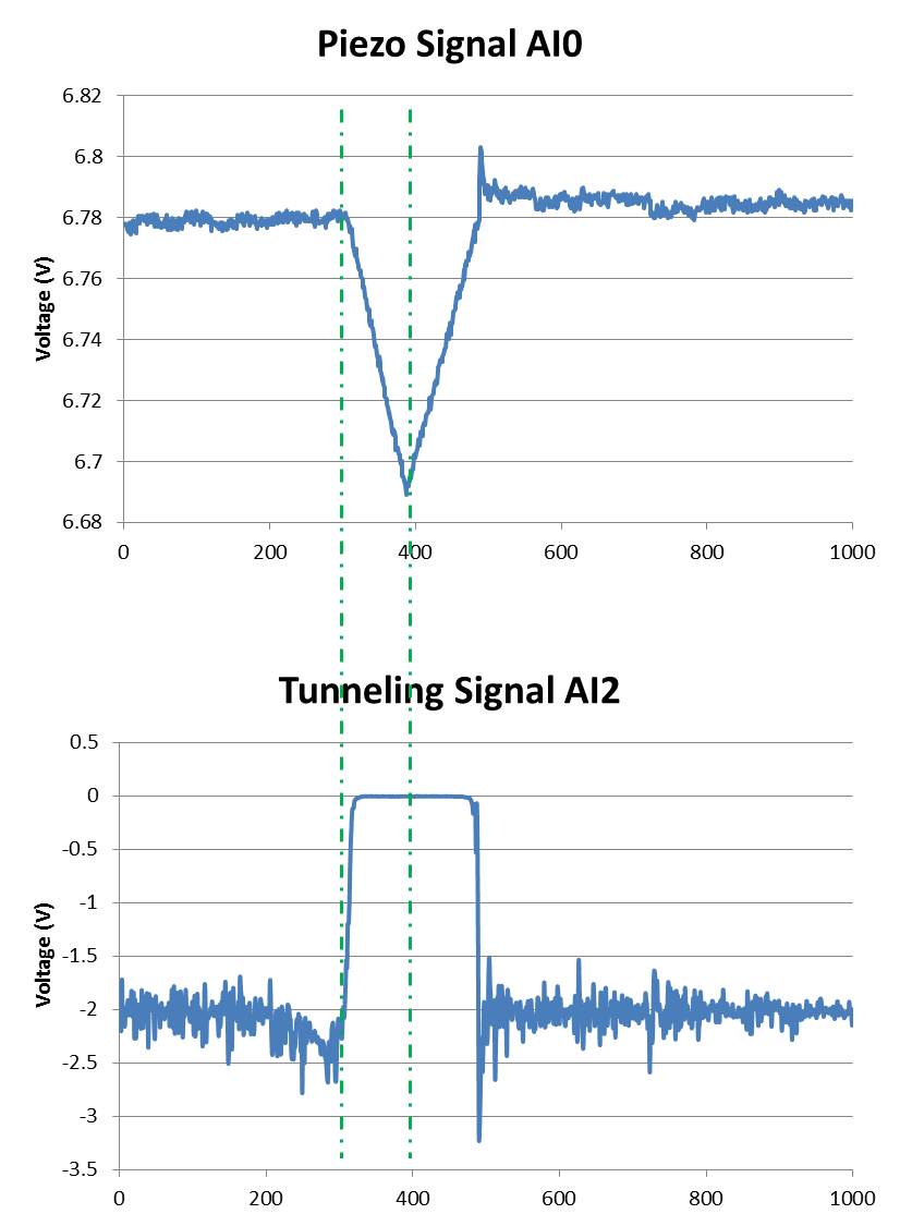
I am using a microscope to tunnel effect from here feeding two voltage signals on my map of acquisition of data USB-6212 (Labview 2013 SP1). A voltage signal is the voltage applied to a piezo in the microscope (AI0). This signal drifting slowly over time and it is noisy. The other voltage signal is a tunnel current is converted into a voltage (AI2) signal (see attached photo):
Ideally, I would like to record the two signals between the lines dotted in a .txt file whenever the event of tip in the top image rises. This should be about every second during a day.
So far, I've written a VI that calculates the moving average of the piezo signal and if the piezo voltage exceeds a certain percentage of the average running it fires a command 'Save as file'. The VI works well for a frequency of 100 Hz, but when I go to 20 kHz, the trigger does not work properly. I am also only watching a lot of a number (in this case, 1000) and if there is a trigger signal in these samples of 1000. So if there's a signal around 0 or 1000 I cut and split into two files that I want to avoid.
I don't have much experience with Labview and probably broke every rule of design in the book.
My question is if there is a smarter way to automatically back up the signal between the same dotted lines at high frequencies of sampling?
I thank very you much in advance!
Hi Mario,.
I rewrote the portions of your VI to improve performance (we hope). No need to three queues. No inquiry unless there is a trigger occurs.
I'm confused by the outbreak that seems to detect the edges of the piezo signal high side, even if the tip is in the negative sense. I modified this logic (eventually) get a threshold top-side of the signal of tunneling.
It is unclear what might happen to 20 kHz. The example shows a constant 1 kHz sampling rate and 1 K samples treated by loop. If the sampling rate is changed to 20 kHz, then the loop will have to run to 20 Hz in order to keep up with the acquired data (@1 K samples per read).
I hope that the joint allows VI (not tested).
-
How to calculate the accuracy of the NI 9239 AI module
Hi all
I'm in the market for an AI module that can help me solve the corners with a precision of 1/10 of a degree. I'm having a problem solver and I want to do the work of a resolver to linear converter by reading in the signals and make the calculation with a NI 9239. I'm just trying to understand if I can get the precision, I need him. How can I do to understand this. I don't want someone to do it for me just to help to step through it.
The 9239 has 24-bit resolution, and I use it since +/-10V, so a range of 20 volts. That should give me a precision of
20/((2^24)-1) = 1.19 x 10 ^-6 V/bit
Is this OK, so I should be able to get a precision of 1/10 of a degree?
You should check at the top, not in the passage by zero, because the voltage changes more slowly at the top.
0.5 * 7 * (Sin (90) - sin (89.9)) = 5.33E - 06 V
It comes to the change, you must be able to detect for your resolution of 0.1 degree. Of course, when a phase is steep, the other phase is close to zero.
Lynn
-
I'm a DJ and use my laptop to do my shows including video/karaoke. Until last Wednesday, I had absolutely no problem coming out of the VGA port on my Toshiba Satellite L355-S7907 and converted into an S-video signal to my mixing console. Last Wednesday the video failed and I am unable to get it working again. Through diagnosis, I determined that the VGA port on my laptop does not send a SIGNAL. It does not detect when the devices are connected and I am able to change my settings to display extended - desktop but televisions AND computer monitors didn't detect any signal when hooked to receive the video. The nearest aid element I found is using the FN key with F5 to change my output - none of these options change anything as an output. I've currently defined (as she was) on the extended desktop LCD/CRT. Please indicate whether it is a fixable problem or if the port VGA itself is bad and cannot be repaired. Thank you.
Hello liquisilver,
You may want to try to go to your device manager by clicking Start and enter "Device Manager" in the search bar or access it from your control panel and search for "graphics cards" and click on the x next to it to see the list of adapt, if we have a yellow triangle next to it , this is probably what is causing your problem, double-click the adapters, you will see a new window with four tabs on the first tab "General" review the State of the device, if there is an error message, consider the nature of the error, if you don't know how to fix the error, visit: http://support.microsoft.com/ for more information and to find a solution You can also reply here with the error code. If it says that the device is functioning correctly, you should click on the driver tab and click Update driver to see if that solves your problem. If this isn't the case, you should consider consulting the Toshiba support site if your computer has the original video card installed and reviewing the support section for your computer model. It is difficult to tell if it's a hardware or software problem based on the information in your question. Try the above steps and view the results.
-
Brick power for W520 buzzing for the use
Hi all
So I use a Lenovo W520 bought in the States during his studies in Berlin. I just got here, and though my converter/adapter handles the change of 230 (or 220: Berlin...) to 110, and the brick said it works with 100-240, my power brick cable bubbles. It heats more than usual and the only side effect is the buzz, but it scares me a little.
It doesn't seem to be any mention of the buzz and most of the things I found tend to show that things are well with laptops lenovo if you use a converter, but I want to just make sure. Any help would be greatly appreciated.
Thank you.
Plug the power supply directly to the wall socket (get the adapter for the Germany). The hum occurs because your 220/110 converter which does not sinusoidal signal.
-
H P S2031 monitor: monitor S2031 P H card
I am with the purchase of a Dell Inspiron I3543-5752 from bestbuy. I want to connect a H P S2031 monitor to it. Dell card does not have an HDMI port. Is there a cable that allows you to convert the Dvi - D input signal on the monitor? I am an amateur, and this can be basic but am at a loss. I also have a Verizon WiFi modem for DSL signal. Is this Actiontec GT704WG Rev B considered as comparable with a Wi - Fi 802.11n?
Hello
A HDMI to DVI - D cable will work. Wi - Fi 802.11n is backward compatible with other by consequent GT704WG (with the wireless g) will work.
Kind regards.
Maybe you are looking for
-
Why not the films I did with iMovie 10.1.2 by sharing the file play on anything but my computer
Movie with iMovie 10.1.1 and 10.1.2 and sharing file then responsible for the thumb drive can be displayed on my computer. PS3 shows corrupt file, Media Player WD is trying to read but the video is degrading and uneven sound, Samsung TV wonder for i
-
I want to add my Canon MP190 printer.
On IE, I have a printer icon on my toolbar. I can't get one on Firefox. How can I print?
-
Hello! We have deleted projects and clips in iMovie so only 30 seconds rest. Even iMovie use 4.9 GB iPad-memory documents and data. Please we advice how to free this memory. iPad Mini, 16 Gb, IOS 9.2.1 iMovie 2.2.1 Best regards!
-
Pavilion 550-138nc: new PC does not start
Hi all I just got a new 550-138nc PC Pavilion. When I turn it on I get the boot that device message is not found and that I should install the operating system on hard drive (3F0). When I ran F2 system diagnostics, everything is OK mind no error mess
-
Connection of device to USB device?
By using the 'comm:USB' StreamConnection, the device will support a USB connection from device to device with a microphone-to-microphone cable?