Copy the attributes of an Expression between input and output
Hi allPlease let me know is possible to copy the attributes of entry and paste it into the attributes of output of an Expression inside the mappings.
I have a number of columns in the table.
Thank you
Salih KM
Hello
It is not possible using the design center of gui.
But you can do this by using the omb. Just adopt the code according to your needs (project, mapping and exploiting the name) and paste it into the omb * more windows of the design center.
OMBCC '/MY_PROJECT/MYT_DB'
set attributeList [OMBRETRIEVE MAPPING 'MAP_EXPRESSION' OPERATOR 'MY_EXP' GROUP 'INGRP1' GET ATTRIBUTES]
foreach attribute $attributeList {
  set dataType [OMBRETRIEVE MAPPING 'MAP_EXPRESSION' OPERATOR 'MY_EXP' GROUP 'INGRP1' ATTRIBUTE '$attribute' GET PROPERTIES (DATATYPE)]
  set length [OMBRETRIEVE MAPPING 'MAP_EXPRESSION' OPERATOR 'MY_EXP' GROUP 'INGRP1' ATTRIBUTE '$attribute' GET PROPERTIES (LENGTH)]
  set precision [OMBRETRIEVE MAPPING 'MAP_EXPRESSION' OPERATOR 'MY_EXP' GROUP 'INGRP1' ATTRIBUTE '$attribute' GET PROPERTIES (PRECISION)]
  set scale [OMBRETRIEVE MAPPING 'MAP_EXPRESSION' OPERATOR 'MY_EXP' GROUP 'INGRP1' ATTRIBUTE '$attribute' GET PROPERTIES (SCALE)]
   switch $dataType {
     NUMBER { OMBALTER MAPPING 'MAP_EXPRESSION' ADD ATTRIBUTE '$attribute' OF GROUP 'OUTGRP1' OF OPERATOR 'MY_EXP' SET PROPERTIES (DATATYPE, PRECISION, SCALE) VALUES ('$dataType', $precision, $scale) }
     DATE { OMBALTER MAPPING 'MAP_EXPRESSION' ADD ATTRIBUTE '$attribute' OF GROUP 'OUTGRP1' OF OPERATOR 'MY_EXP' SET PROPERTIES (DATATYPE) VALUES ('$dataType') }
     default { OMBALTER MAPPING 'MAP_EXPRESSION' ADD ATTRIBUTE '$attribute' OF GROUP 'OUTGRP1' OF OPERATOR 'MY_EXP' SET PROPERTIES (DATATYPE, LENGTH) VALUES ('$dataType', $length) }
   }
}
Kind regards
Carsten.
Tags: Business Intelligence
Similar Questions
-
digital output: relationship between input and output values
Hi, could someone tell me if you are using digital lines material OR daqmx (SMU 6358, if it is dependent on the device), what is the value of weight of the inputs that will change the output of 0s to 1s?
Suppose, I write a table of 10 numbers from 0 to 9, which will output look the same?
Thank you.
This is of specific devices, but you will see a pattern the same values across many devices. Of the datasheet for your SMU:
- Continuous positive threshold: 2.2V
- Line negative: 0.8V
Yes 0 - 9V, depends on which direction you're going. It is a grey between 0.8V and 2.2V area because the value will not switch until it reaches the threshold value.
From False to True, you need read a value of 2, 2V. Changes from true to False, you will need to read a value less than 0.8V
This image does a good job of this representative. See the red line (positive course) and green-(négatif cours).

Your title says "Exit" and with the intervention. The above information concerning the digital inputs. The 0V or 5V output feature.
-
Precise triggering voltage input and output generation in the DAQ Assistant
Hello
I wonder if anyone has come across a simular problem with the synchronization of input and output voltage. I use a box 11 LabView and NI USB-6259. I have been using the DAQ Assistant to configure the input and output channel. In particular, my task is to generate a single rectangular "pulse" as the output voltage to drive a coil and once the pulse went to get a signal from a sensor of magnetic field and get a power spectrum. This means that the order and the time during which the DAQ Assistant is used is extremely important. For example, the output voltage channel must be opened first for 2 seconds. Subsequently, the channel of input voltage must be open for 1 second, in which the sensor signal is obtained and post-processed. Only after these tasks are performed in this order he can can be repeated in a loop until the experiment is over. I don't know how to trigger data acquisition assistants (one for entry) and the other for the voltage output correctly. Y at - it a trick?
See you soon
Michael
Hi Dave,.
Thank you that I wired the error strings but the timing issue was unrelated to it. In the DAQ assistant, I simply had to choose the continuous aquistion of the 'samples' methods 'N-switch' for input and output voltage and all works fine now.
Thanks again
Michael
-
copy the address book Outlook Express for Hotmail - can't get in Outlook Express
copy the address book Outlook Express for Hotmail - can't get in Outlook Express.
Lately I often can't get into my Outlook email. I know that I can use Hotmail, but I need my address book. I know that it has to see with the Qwest no longer carring MSN. Can you tell me how to recover or to carry it?
Thank you, Cookie 303-371-6295 or 303-931-4632
The address book is a file with an extension of wab file. Search for *.wab and then you can click on it to open it. You can then go to file | Export | Address book, then save it as a csv file. To import into Hotmail, as in this case: www.windowslivehelp.com because it is where are the experts of Hotmail.
Steve
-
Is there a way to copy the attributes of one composition to another?
I use After Effects 7.0
I would copy the same attributes of Zoom of a composition of 30 photographs.
In Final Cut, you can copy the attributes of one element to another. Or from one photo to another.
Is it possible to do in AE 7?
Thanx
Mike
There are dozens of ways you can go here. You can duplicate the comp, then replace the images in the layout. You can create predefined animations. You can select all the animated properties and copy and paste in another layer. It depends on your workflow.
I suggest that you look into the preset animations. I have over 200 of those custom in my system. They save a ton of time.
-
Make sure that wire you all the inputs and outputs of your node library function call?
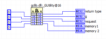
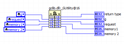
This document says "make sure that wire you all the inputs and outputs of your node library function call.
But all the terminals on the right side of the call library node considered "outputs" referred to in the foregoing statement?
This same document continues to show the right way to allocate memory with this illustration and in the illustration, the right "outputs" are left without junctions.
Am I right in assuming that the only terminals that count as outputs, those who use the code of the DLL (modify) as output? If it is true, then all other terminals output associated with the values entered alone so don't really account as outputs, correct?
In the parameter call-library configuration screen there is a "Constant" check box and the help that he wrote "indicates whether the parameter is a constant." What is this box? for me in the setup of the DLL call
Finally, assuming that a call from the DLL that is supposed to write in these five outputs, is it legitimate to use constants like this to book a space of memory for the output values?
How about if local variables associated with the output terminals are used instead?
Despite the linked document, it is necessary to connect the corresponding entry for simple scalar output parameters (for example a digital). LabVIEW automatically allocate memory for them. If you do not want the entries for all the output wire anyway, there should not be no difference between a constant and a local variable; I would use a constant to avoid useless local variables.
For settings that are only entries, there is not need to connect the outlet side. It's a bit simplistic since all parameters are entered only and get one result (other than the return value), you pass a memory address and modify the content to this address, but LabVIEW manages this dereferencing pointer for you. If you want to really get into the details, learn more about pointers in C.
The "Constant" check box acts as the qualifier "const" on a c function parameter. It tells the compiler that the function you are calling will not change this setting. If you call a function prototype includes a const parameter, then you must mark this as a constant parameter when you configure the call library function node. Otherwise, I wouldn't worry on this subject.
-
synchronize the inputs and outputs on the USB-4431
Hello
I have an application that needs to send a signal on the USB-4431 and then capture it with an entry on the same device.
Aware that I use two tasks to do this, one for input and one for output. I discovered that a trigger (on the RTSI bus) can cycles of sending/capture sychronisé departure operations so that it can be a constant offset between the captured signal and the output signal.
Unfortunately, the code I found is for Matlab. I can't find an equivalent for it in the C API of NIdaq. The method is described here; http://www.mathworks.in/help/daq/synchronize-analog-input-and-output-using-rtsi.html.
What I can't understand is how to implement this on the analog input:
ai.ExternalTriggerDriveLine = 'RTSI0';
Can someone shed light on how to do it?
The rest of the things described here, seems to be feasible with a normal trigger:
ao.TriggerType = 'HwDigital';
ao.HwDigitalTriggerSource = 'RTSI0';
ao.TriggerCondition = 'PositiveEdge';
Thank you
Nirvtek
You can synchronize the HAVE and AO by sharing the start of relaxation between your two tasks.
Choose one of your tasks as the "master" and the other to be the "slave" (any).
Set up a trigger to start of digital dashboard on the task of the slave, and set the source of the trigger to be the trigger of the master's departure.
Assume the following:
The name of your device is 'Dev1 '.
I is the main task
AO is the task of the slave
Here's what you would do to sync the two:
(1) create the tasks I and AO in order that you want to
(2) set up "timing" on the tasks of HAVE it and AO (you choose the sampling rates must be the same or power-of-2 many of the other (for example 100 K, 50 K, 25 K, 12.5 K, etc...))
(3) configure your slave (the task of AO) task to have a numerical advantage start trigger and make the source is the trigger for the start of the task of the master (the task to HAVE it). In our case, "Dev1, AI, StartTrigger.
(4) write data (a sine wave, presumably) to your task AO
(5) start the task from the slave (the task of AO). The task of the AO is now in the 'Started' State, but given that you've set up a digital trigger early, it won't actually generate data until he sees a numerical advantage of 'Dev1, AI, StartTrigger.
(6) to start the main task (task to HAVE it). The task of the AI does not have a trigger digital early, so the software will immediately generate a start trigger, which also causes a numerical advantage on "StartTrigger/AI/Dev1", which causes the task AO start at the same time.
7) read your job to HAVE.
You will notice a few 0 at the beginning of your data to HAVE. It's a result of something called "Filter Delay" and it is an inherent characteristic of all DSA devices - see the manual to use DSA and this article for more information on what is and how to cope.
I hope this helps.
EDIT: I just noticed that you pointed out an existing C example. It's exactly what you want. I don't know why you have a resource error booked - I tried it myself and (after changing the AO will of +/-10V to +/-3 .5V), it works beautifully. Try to reset your device to the MAX (or DAQmxResetDevice() of your program)
-
A sound card internal Mac pro 3.1 what they do?
And if yes where can buy one?
I need more input and output it attach to my PA and recording, hardware as I do with a windows PC.
The mac comes with a microphone and a single output with terrible impact when it is connected to my sound stuff.
A few people responded to your post above. Might be better to explain what your needs are, rather than starting a new discussion here.
-
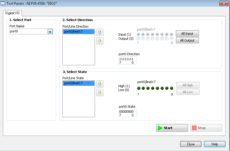
Individual access to the inputs and outputs on a single port (PXI-6509
Hello
I use PXI-6509 and this sentence taken from the Manual:
"You can use each of the DIO lines as the input to a digital static (DI) or digital output (DO) line"
leads me to believe that each individual DIO can be defined as input or output (even within ports), but picture:
shows that these ports can be defined as inputs and outputs in the same port.
On another card 6284 with DIO, I can put them individually.
Can someone confirm that the 6509 is correctly?
Best regards
Adrian
-
Synchronization of the inputs and outputs with different sampling frequencies
I'm relatively new to LabView. I have a NOR-myDAQ, and I am trying to accomplish the following:
Square wave output 10 kHz, duty cycle 50%.
Input sampling frequency of 200 kHz, synchronized with the output that I get 20 analog input samples by square wave, and I know what samples align with the high and low output of my square wave.
So far, I used a counter to create the square wave of 10 kHz, display on a digital output line. I tried to pull the document according to (http://www.ni.com/white-paper/4322/en), but I'm not sure how sample at a different rate than my clock pulse. It seems that this example is intended rather to taste one entry by analog clock pulse. There may be a way to create a faster clock (200 kHz) in the software and use that to synchronize the analog input collection as well as a slower 10 kHz output generation square wave?
I eventually have to use the analog inputs to obtain data and an analog output to write the data channel, so I need the impetus of the square wave at the exit on a digital PIN.
How could anyone do this in LabView?
Hi Eric,.
All subsystems (, AO, CTR) derive from the STC3 clocks so they don't drift, but in order to align your sample clock HAVE with pulse train that you generate on the counter, you'll want to trigger a task out of the other. I would like to start by a few examples taken from the example Finder > Input and Output material > DAQmx. You can trigger GOT off the train of impulses, start by Gen digital Pulse Train-keep -you probably already use a VI like this to generate 10 k pulse train. AI, start with an example like Acq Cont & chart voltage-Ext Clk - Dig Start.vi-you'll want to use the internal clock so just remove the control of the "Source of the clock" and it uses the internal clock. From there, simply set the "Source of the command" either be the PFI line generates the meter, or ' /
/Ctr0InternalOutput '-assuming that you are using the counter 0. You'll want to make sure that the start of the task HAVE faced the task of counter I is ready to trigger off the first impulse. They should be aligned at this point. For debugging, you can use DAQmx export Signal to export the sample clock - you can then brought the train line and the PFI pulse to make sure that they are aligned.
Hope this helps,
Andrew S
-
What is the organizational structure of microsoft and what the different type of organization between microsoft and linux
Microsoft communities must answer a technical question about Windows 8, Windows 7, Windows Vista and Windows XP.
If you have a technical question, please let us know. This type of information you are requesting is not available in this forum. Do a search on the internet, and you should be able to find this kind of information.
Sincerely,
Marilyn
-
Original title: M2TS
I copied the 2 files to a DVD movie and he changed the .m2ts file format and it is not supported by Windows Media Player. How to convert files in a file type supported?
Hello
The files have already been burned on a DVD and therefore cannot be converted. However, you can download and install third-party codecs to play .m2ts files.
Codecs: Frequently asked questions
WARNING OF THIRD PARTY
Using third-party software, including hardware drivers can cause serious problems that may prevent your computer from starting properly. Microsoft cannot guarantee that problems resulting from the use of third-party software can be solved. Software using third party is at your own risk. -
Can I copy the computer my brother Vista System32 folder and navigate through it on my Windows 7 computer? I like to compare the old and the new and see what works, but I'm not sure it's legal, and I assure you.
Hi Aaron Campbell,
To help focus in the right direction, I would like to know what exactly are you trying to accomplish?
You try to compare windows vista and windows 7?
Yes, you can copy the folder system32 on a flash drive and then compare it with windows 7.
The System32 folder and its subfolders contain files of system operating base for your installation of windows operating system. See the link below for more information:
http://TechNet.Microsoft.com/en-us/library/bb457124.aspx
Note:
ؠ You cannot copy all the contents of the system32 on the flash player folder because the essential components are in use.
ؠ Do not replace or try to copy the system32 (from windows vista) folder for drive C on windows 7, the computer may become unstable.
You might want to know
Compare windows 7 with windows XP and windows vista.
http://www.Microsoft.com/Windows/Windows-7/compare/versions.aspx#
Thank you, and in what concerns:
Ajay K
Microsoft Answers Support Engineer
Visit our Microsoft answers feedback Forum and let us know what you think.
-
Using the same PIN for input and output
Hello
I would use a single PIN for input and output.
I'm experimenting with writing a driver for the DHT11 that using a single interface
I have the following code to open the PIN, but it fails
GPIOPin dhtPin = (GPIOPin) DeviceManager.open (new GPIOPinConfig (0, 17, GPIOPinConfig.DIR_BOTH_INIT_INPUT, GPIOPinConfig.DEFAULT, GPIOPinConfig.TRIGGER_NONE, false));
VM - iso [DAAPI] =-1: not supported direction was placed for 17 GPIO pin number. Open failed
jdk.dio.InvalidDeviceConfigException
-com/oracle/deviceaccess/gpio/impl/GPIOPinImpl.openPinByConfig0 (), bci = 0
com/oracle/deviceaccess/gpio/impl/GPIOPinImpl. < init > (), bci = 87
-com/oracle/deviceaccess/gpio/impl/GPIOPinFactory.create (), bci = 6
-com/oracle/deviceaccess/gpio/impl/GPIOPinFactory.create (), bci = 3
-jdk/dio/DeviceManager.openWithConfig (), bci = 49
-jdk/dio/DeviceManager.open (), bci = 6
-jdk/dio/DeviceManager.open (), bci = 2
-dht11 / DHT11. < init > (DHT11.java:42)
-dht11 / DHT11. < init > (DHT11.java:37)
-dht11/DHT11Midlet.startApp(DHT11Midlet.java:25)
-javax/microedition/midlet/MIDletTunnelImpl.callStartApp (), bci = 1
-com/sun/midp/midlet/MIDletPeer.startApp (), bci = 5
-com/sun/midp/midlet/MIDletStateHandler.startSuite (), bci = 264
-com/sun/midp/main/AbstractMIDletSuiteLoader.startSuite (), bci = 38
-com/sun/midp/main/CldcMIDletSuiteLoader.startSuite (), bci = 5
-com/sun/midp/main/AbstractMIDletSuiteLoader.runMIDletSuite (), bci = 132
-com/sun/midp/main/AppIsolateMIDletSuiteLoader.main (), bci = 26
I have the following permissions value
jdk.dio.gpio.GPIOPinPermission "*: *" 'open, setdirection '.
jdk.dio.DeviceMgmtPermission "*: *" 'open '.
I tried a few other pins too, I don't know if some ankles are entered or only output pins.
Any help would be appreciated. I could not find documents explaining how to configure more than one action for a permission ( 'open, setdirection'), so I tried just until he stopped to complain about the values...
What I need is to open a PIN, set it OUT, write a few high and low values... set it to the direction of the ENTRANCE, and reading back high and low values... But right now my GPIOPinConfig seems to be problematic
(... Configuration of the meaning to DIR_INPUT_ONLY or DIR_OUTPUT_ONLY, works until I try to change the direction of the port - what is expected...)
Hi Charl-
As far as I KNOW, he is there no current plan to apply 1 thread in Java ME Embedded.
I also looked at Pi4Jand they do not also support 1-wire, however, there is an enhancement request to add support for the bit hit Linux driver will have to perform 1-wire work.
The raspberry pi support it, it's just Java ME holds back me.
BTW - the article has been referenced in the enhancement request notes that he is not taken in native support for 1 wire on the Raspberry Pi - it requires a Linux kernel driver module.
Tom
-
Hello! I am a family oriented photographer and have a bit of trouble to keep the colors of files exported between lightroom and photoshop consistent. I edited my images on 5 Lightroom and export TIFF files after changing color ProPhoto RGB space. Then, I opened a picture at once and changed the settings of Photoshop CC ProPhoto RGB color (under the workspace). When I was editing on photoshop, I tried to export the image, but the colors seemed different, a bit washed out and blue, from the color of the workspace, I was on. I don't know how to solve this problem. Please notify.
Thank you very much for this! Color sorted
Maybe you are looking for
-
AK031TX: Cyberlink PowerDirector software
Is the Cyberlink PowerDirector software pre-installed when I bought the HP Pavilion Gaming AK031TX permanent or termination as mcfee recently laid off? Thank you
-
Satellite A100-692 - how to reduce graphic memory?
Hello!I'm looking for information how to reduce graphic memory. I have Satellite A100-692, PSAA9E-09900QGR and install 1024Mo RAM but 512 MB is dedicated to graphics memory. Because of this I have 512 MB of RAM in real-time only.I would change it. Sh
-
Watermark to Photo in OSx El Capitan
After searching for the best app for tattoo picture in OSx El Capitan, I found "Watermarker2". It comes as an extension of the "Photos" application You can register different styles of watermark. First create the watermarks in the application of the
-
How to check if a table contains a table
I have an array array1 say array that contains several tables. I have another table say array2. Now, I want to check whether or not arrray1 contains array2. How can I check this?
-
NET Framework error code 0 x 643.
My computer tried to install .NET Framework 3.5SP1 and update of the family for several weeks now and a message says: it has not been installed. Today I received a serious error that sent me to a link to make sure that all my updates critics have be