Count of analog shooting
Hello
I try to use the edge detection analog to increment a counter, I'll read then leave at regular intervals. I keep hitting brick walls trying to perform/adapt the examples on the site of NOR.
I use a cDAQ-9174 chassis and a map of analog input of NI9223 with LabVIEW 2014 SP1.
Any suggestions would be greatly appreciated.
Thank you
Emach
Hello Emach
First, I'll share with you a link where you can see the function each device can therefore use, see below:
http://zone.NI.com/reference/en-XX/help/370471Y-01/TOC40.htm
http://zone.NI.com/reference/en-XX/help/370471Y-01/cdaqmxsupp/ni_9223/ (For 9223)
On the other hand, I thought that you can create a VI when you do the analog signal acquisition and when that signal has a specific value, you can increase a counter (by software).
Concerning
Tags: NI Hardware
Similar Questions
-
Synchronization of two inputs frequency meter with several analog inputs
Hi all
I'm relatively new to LabVIEW and I'm trying to collect data from multiple sources with calendar sync on the acquisition, but I can't understand. My problem is that I have two inputs frequency meter, an optical tachometer reading one pulse per revolution and a max flow meter machines with a 12000 k coefficient. I can't find a way to synchronize the calendar with my multiple analog inputs. I tried to first get the speedometer to synchronize with the analog inputs following the example linked here. (https://decibel.ni.com/content/docs/DOC-10785) So far every time I run it I get an error on the DAQmx read timeout or an error "several sample clock pulses have been detected" (see image). It seems if I slow the way to down to say 10 hz and make sampling rate ensure that the tachometer signal is more than 800-1000 rpm (13-17 Hz) before starting the VI then the program will run without error until the ROTATION speed is below this threshold, then the "sample Multiple clock pulses" error occurs. The code is attached below.
Does anyone know of a better way to synchronize the entries of frequency of the counter with analog inputs? I would like to have a VI that can display 0 RPM (and possibly 0 flow as well, but I think I need to understand the timing of a meter before I have add another, because it seems that I can't have two counters to the same task). Any help on this would be greatly appreciated.
LabVIEW version 13.0
Chassis cDAQ-9178 with NI 9401 for both counter inputs and NI 9205 for the analog inputs.
Thank you!
Richard
I know the error requires to restart the task at least (this particular error puts the material in a State that cannot be recovered from during execution of the task - I've been down this road before) but I'm surprised that you would have to delete and re-create the task altogether. And then I had to do this to workaround other questions in the past. It is awkward and should be considered a bug, if this is indeed the behavior.
Honestly, regardless of this bug, the way the material dealing with the situation of several sample clock edges makes measures of sampling frequency clocked essentially unusable for purposes of synchronization (in my opinion anyway) If you encounter a more slow than your sample clock rate. You are supposed to be "synchronization" of the measure, but it really no longer applies if you have to restart the task over and over again (if you must delete it or not).
Workarounds can get kind of creation (which isn't really a good thing). For example, you can configure a measure of implicit frequency to keep a buffer of frequencies and use a leader board task (source is the frequency signal, sample clock is the sample clock HAVE) to establish a correlation between the index of your buffer of frequency for singing HAVE sample clock.
Best regards
-
Dedicated for each channel from multiple channels in a single task task disadvantage
Hello
My current acquisition software (C + c++ / GCC) encapsulates the methods rather clumsy niDAQmx C to interface with the data acquisition equipment in a class that represents a task of acquisition. This way I can create several instances, for example counter input, analog input, analog output, their terminals and the class supports all work low level as ensuring input analog fake internal is started if there are only counter entries such as the sample clock starts, or configure reminders N-sample, etc.
It seems to work very well, and also the time seems to be good, because first of all the tasks on multiple instances of my wrapper. For triggered early, that I use
DAQmxCfgDigEdgeStartTrig(mTask,mTriggerTerminal.toAscii().constData(),DAQmx_Val_Rising)in-house.
Now my real question: what is the advantage of multiple channels, when everything seems to work fine with multiple tasks and only one channel per task? I don't see the disadvantage, it would first classify necessary acquisitions in types (I, ao,...) because several strings in a single task must be of the same type. With my approach I need not care because each channel still gets its own task.
I don't know I'm missing something here. Maybe someone can explain it to me, maybe some limitation of multi-tasking, I have not yet read.
Hey!
Unless you specified for managing the it (simultaneous sampling) or modular instruments and hardware devices (see link )
You cannot perform two tasks at the same time that access to the analog inputs, for example, because the
ADC is a shared resource that is connected to a multiplexer, and that only one task can work in it at a time given. (see here )
Similar restrictions often apply to other types of operations.
I'm not aware of any performance issues, perhaps a little more memory could be used.
So as long as your hardware supports what you are doing, you should be ok, I think,
and it is only a question of clarity and intelligibility, ease of use and structure.
As you use classes, I'm sure you've heard about encapsulation - so it is a
question of how you want to design your application.
In addition, when you work in LabVIEW, tasks feel more natural to the principle of data flow, because you have a thread for your data acquisition,
and it works very well with our modes of standard design.
So, if it is better for you (and works with the hardware), you can give all the channels its own task.
Hopefully this might clarify some things,
Kind regards
Rome
OR Germany
-
How can I check if the counter entry is synchronized with the analog output?
Hello
I'm working on an application for counting photons. I use two channels of analog output on a PCI-6713 card to send a frame model to a set of XY scan mirrors. I then a photon count unit that emits a TTL signal when the photons are detected as a result of this raster analysis. I then use a surfboard USB-6211 to count the edges on this TTL signal.
I have problems that seem due to synchronization problems. I use the sample AO on the PCI-6713 card clock like the door of my meter on the map USB-6211. I use a trigger to start digital to analog output and a trigger of arms for the entrance to counter early. Is there a way to check that the analog output and counter entry of start of operations at the same time and are are synchronized? I basically want to monitor and compare the ao real sample of the PCI-6713 card clock door signal used by the jury of the USB-6211. I was able to export the sample AO clock and watch it on my oscilloscope, but not the signal from the door of the USB-6211.
Thanks for your help,
Brian
Update... It turns out that there is no problem of synchronization between my meter input and the analogue output. There was a difference of impedance when I connected my unit of counting photons to my USB-6211. This caused an error variable count rate. After accouting for this shift, the problem disappeared.
-
How to trigger and outputs analog and digital Outout tasks begins on a counter to start?
Hello
I'm trying to synchronize the start of a task outputs analog, a task of digital output and a task of counter. I want to start the counter to serve the master trigger and analog and digital tasks to synchronize his departure.
I guess I need something like:
analogOutputTask.Triggers.StartTrigger.ConfigureDigitalEdgeTrigger ("?", DigitalEdgeStartTriggerEdge.Rising);
digitalOutputTask.Triggers.StartTrigger.ConfigureDigitalEdgeTrigger ("?", DigitalEdgeStartTriggerEdge.Rising);
analogOutputTask.Start (); Slave 1
digitalOutputTask.Start (); slave 2
() counterTask.Start; n / / master
Where? is a string specifying a command source for the beginning of the task of the meter. However, I can't find what this string. Any suggestions?
Thank you!
-Jon
Just FYI, the solution to this problem as well as some other ones is encapsulated in a short example .NET, I created. It is on the Web site of EITHER:
http://decibel.NI.com/content/docs/doc-15500
This project shows how to synchronize all your analogue/digital outputs through tasks and forums in terms of synchronizing Calendar and start clock.
-Jon
-
Outputs produced by the analog input job Retrig delay counter
Hi all!
First of all, I want to thank everyone on this forum who take the time to answer the questions, this forum has been invaluable to me. I have a question about delays in adjustment to the pulse output of a counter, like what is described here. My question is related to another, asked hereon the trigger of an analog signal and producing a pulse for each triggered event. I have this job and can be seen in the attached vi. Basically, now I'm able to produce a TTL pulse whenever my analog signal passes a predetermined threshold. I have also documented the vi to my best understanding, if I have something wrong in the documentation, please let me know.
In any case, now that I have a pulse at each outbreak, I would like to be able to adjust the delay of events so that the pulse is not produced until the period n/20 (n = 0, 1, 2,... (19) what I expect to see is a similar pulse train in 'fig. 2' in the article, where the white pulse is the counter pulse, and the pulse red would be the same as my analog signal. So, for example, if I had a 281Hz signal, I want to produce a single pulse with a width defined by the user whenever my signal crosses a threshold (it's zero delay: 0/20); This part may be made using the vi attached to this subject. Now I want to delay this impulse as to each trigger event, a pulse is not produced until 1/20 of the period, or 0,000178 seconds after the trigger.
Looking at my vi, I think that if I change the output channel of the meter to 'CO Pulse Time' and then set the respective initial delay, time and little time, I can get delayed impulses mentioned in the article. Correct me if I'm wrong, but I think that basically 'big time' controls the pulse width. 'initial period' is what controls how long to wait after the first trigger event is reached, before generating a pulse, but this applies only to the first impulse and not the rest; and finally 'small time' is the time to wait before the next pulse is created.
Earlier today, when I use the CO Pulse Time option, it seemed to work properly for me to a certain degree. At low frequencies the impulses seem to trigger to each event when the pulse width is set at 2.5% of the period. When I tested at 281 Hz with a pulse width, 'big time' of 0,000089 sec and without anything wired for the 'initial delay' or 'small time', the impulses seem to ignore systematically each triggers 2... that tells me that something is wrong in my settings, rather than problems with the sample clock. So I decided to connect '0' to 'small time', but then I got an error message indicating that some time may be less than a value (I forgot what the error message). So I concluded that I must not understand what these terms mean.
Sorry for the long explanation, but I really need help with this. So let's say that the first set of data, I want to acquire is at zero delay, such as pulses are generated at each triggering event like how I have my VI now; so, for the next set of data I want pulses to generate 0,000178 seconds after the trigger threshold; so, for the data set third, I want to pulses to generate 0,000356 seconds after the trigger threshold; and so on... How should I do for this? Thank you very much!
Hello!
Please post on the Forums OR! I think the main issue here is that you are sampling not fast enough to catch all of your high. So you set your high dry 0,000089. You will need to substantially increase the frequency of sampling in order to catch all these. Something around 25 k should do the trick.
To the extent where using the time counter Pulse, you're totally on track. I think that the use that the delay will do the job.
I hope this helps! Let me know!
-
Read the counter timeout in synchronized to count-analog input
Ciao, Giovanni.
The two tasks are run in parallel so there is no guarantee which task starts first. I suspect that when you are away from the counter samples, it is because the task of analog input before starting the task of counter. In this case, the task of counter would be ready to accept examples of clock and may be missing some edges of the clock at the time wherever he is started.
One way to solve the problem would be to use the wires of the error in order to ensure the time started the task of counter in front of the task of analog input. You can also use a sequence structure to do that.
The counter is sampled on each edge of the sample clock HAVE no matter what you set the 'rate' of entry to the. When you use an "external" clock (external to the task that is), the driver uses just the entry rate to set some default parameters (size of buffer for example).
If you have any questions, feel free to ask!
Best regards
-
6143 - PCI or PCI-6133: simultaneous reading of analog, digital, and counter
Hello Board,
I want to use a PCI-6143 or 6133 to acquire permanently synchronized values ports analog, digital, and counter on the same device.
I use vb.net to build an application that reads the values of the device buffer and stores them in lists for later use.
By reading some other threads I discovered, that all the S series devices are able to use a source of material for the release of the digital ports.
Here are two among them? What meter ports, they suffer from the same problem?
Software trigger is no option because the sampling rate must be accurate.
Thanks in advance for the answers,
M.B.
Hi M.B.
6143 does not support Correlated DIO (i.e. clocked by the hardware), the 6133 (see-> digital I/o--> Timing). As a result, synchronized doing of entry works with the latter. Acquisition of meter in the buffer is available on both devices. The 6133 also authorizes analog and digital triggering.
To synchronize these tasks, you need to export a clock signal (sample clock HAVE for example) and take to the DIOs and counters for an acquisition in the buffer. An example for synchronization of AI and DI is given once you install the DAQmx driver in the
Please let me know if you need more specific information.
Kind regards
Peter
-
someone at - it an idea on how I can get counter strike so quickly on my pc and not so fragmentary and lag., is the first person shooting game and not looking to spend money? someone help me please! and thank you!
# You have not given any information, except for what you are trying to run.
As far we know you run with some processors Sempron/Celeron and 512 MB shared memory with an on-board video camera. In addition, you might have a suite of protection oversized running on your system to keep you safe from Internet predators and a bunch of other things you love continues to run in the background.
Here again, you can have a dual core or higher processor 1.8 GHz or more fast speed with 1 GB or more of memory and a 512 MB or higher video card (do not share memory with the system) which has installed the most recent drivers. Also you can have only a basic product antivirus running, by using the built-in Windows Firewall and you want to keep your system with as little as possible run so that most of your resources are available.
Probable - in any case - other than generalities such as:
(1) make sure that few runs when you play the game (with the exception of the game) as possible.
(2) make sure that you have the latest video card driver installed for your video card.
(3) make sure that you have the latest driver installed for your motherboard chipset.
(4) make sure that you have the latest audio driver installed for the audio device.
(5) make sure that you have the latest network driver installed on your device on the network.
(6) run the game with its smaller settings with the same extras disabled as you can stand it. Shadows are nice - but will slow down your system.And the advice that you said that you do not want to (while remaining general because we do not know the details of your system):
(1) buy a more grand/more fast video card to replace yours.
(2) buy more memory system in case you run low during playback.
(3) replace your processor with the highest that will take care of your particular motherboard.And the most extreme:
(1) buy a system that has a little above the minimum specs for the best interpretation of this game is that you are trying to play.
-
I want to rename and move files from a shoot 5 d on a new drive. I would like to use the functionality of the increment to count, but since I have to get out of each file to the following file, it starts again at 1. What is the best way to do it?
HI -.
As a prelude to 2014.0, we have added a feature allowing you to choose what number to start the increment of. Look in the section ingest Rename dialog and change your preset. When you click the button, you should see the option "Custom Auto Increment". This will allow you to choose what number to start on. We've also added a few newspapers to try to remember where let prelude last successfully interfere the operation by using this option. So, in theory, to remember the number for you. But if it isn't (maybe you want multiple kickoff ingested at the same time) you can always manually set the number to start with.
Check that out and let me know how it works for you.
Kind regards
Michael
-
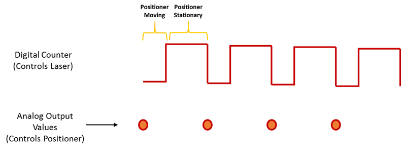
Analog output with counter Falling Edge
Hi all
Here's the iamge which describes what wishes to accomplish. I would like to trigger that the AO output with the edge of the fall of the meter.
I have set the clock for my AO as the counter.
The analogue output should be raised whenever the Digital signal meter falls
SAMPLE_SIZE = 80
SAMPLING_RATE = 40 #Samples are written every 25 milliseconds
TIME = float ((SAMPLE_SIZE) / (SAMPLING_RATE))CREATE TASKS
CREATE CHANNELS OF AO
CONFIGURE THE TIMING CHANNELS
DAQmxCfgSampClkTiming (taskHandleAO, "PFI12", SAMPLING_RATE, DAQmx_Val_Falling, DAQmx_Val_FiniteSamps, SAMPLE_SIZE)CREATE TASKS
CREATE A CHAIN COUNTER
# Time high-low + time equals 25 milliseconds and is proportional to the frequency of sampling
DAQmxCreateCOPulseChanTime(taskHandleD,"DAQ/ctr0","",DAQmx_Val_Seconds,DAQmx_Val_Low,0.00,0.005,0.020)# The values of voltage DAQmx writing
DAQmxWriteAnalogF64(taskHandleAO,SAMPLE_SIZE,0,10.0,DAQmx_Val_GroupByChannel,Voltage,None,None)# DAQmx AO task start
DAQmxStartTask (taskHandleAO)# Counter DAQmx Start task
DAQmxStartTask (taskHandleD)#TIME is equal to the total time for the writing samples
DAQmxWaitUntilTaskDone (taskHandleD, 2 * TIMES)I get an error every time that I run the task:
DAQError: Over Acquisition or generation has been stopped until the required number of samples were acquired or generated.

 function DAQmxStopTask
That's because my AO task is stopped for some reason any.
Is there an obvious problem with the code. Can it be structured differently?
best regards,
Ravi
I do all my programming in LabVIEW, so I'm pretty limited to help with programming syntax text. That being said, here's what I * think * I see:
Your AO task issues a call to DAQmxCfgSampClkTiming, but is not your task of counter. This probably leaves you with a meter spot which creates only a single impulse, which causes only a single AO D/A conversion. In LabVIEW when I need a pulse train, I would call a similar function of the synchronization with the clock mode is defined as 'implied '.
Hope this helps you get started, I don't know enough to give you the specific syntax in the text.
-Kevin P
-
Hello
I have a power meter which provide the USB driver and a Labview program to get the data and NI USB-6221. The project I am currently working on the needs of:
1 acquire two signals (inputs of simple tension), pressure frequency KHz
2. acquire a flow signal, the output signal is 0 to 5V pulse, each pulse means 0.4 ml volume. So I use a voltage inflows to count impulses in certain period of time (in this case, 1 S) for water flow. ; KHz sampling frequency and the 1 Hz update rate
3. acquire a signal of engine speed. The output signal is pulse square wave whose frequency is related to the speed. I use a REIT port to measure the frequency. Sampling rate: Auto
4 give output voltage sine or square wave, I use AO do that.output rate: Auto
5 acquiring by VISA electricity meter data. Data update rate: every 50ms
Currently, all the 5 tasks work well separately. But when I put them together, some signals are beginning to hang, for example, pressure signals sometimes give nothing.
Another problem is the data record. I programmed the VI in such a way that whenever I press the button 'save start', he begins to record data and save them in a .cvs file. For some reason, I always get only the data in the first table. Coult someone help me? I download my code as follows
Hello
What I meant by open, write, close. For any type of file you are using.
Open the file, which produces a reference, then put the mention in a registry to offset.
Write data, using the function write (for this type of file) and the reference.
When you are finished, close the file reference.
Writing in the spreadsheet opens, written, close all at once. It is very good for this type of application.
***
The issue of the loop is more general. I would like to say first of all, I want to say that since each loop works on its own, it is own VI, and that this program has put all this into a single VI, which has a method to solve the problem is to disable all the loops and allow them one at a time to see if there is a culprit responsible for.
Using multiple loops executes the code at the same time, and some loops would be cycle faster than others, especially if some of them are loops just as they are.
Communication between the loops is a test to the address if necessary.
Running all these signals through different loops DAQ must also be examined. Don't know what questions are for read and write somewhat randomly in the channels.
-
iCloud says it is complete, but it is count files that do not exist
Hello world.
I have a problem with iCloud reports that it is full, but when it calculates the space that I used, it's counting the things that have been deleted and removed from all appliances (including bins/albums "recently deleted").
I was testing my iPad battery life, because I want to do a shoot and I wanted to see how long I could record for. On both devices, I made a video of 10 GB and a 20 GB video.
As soon as I finished filming, I deleted the videos. Also, I went into the album "recently deleted" and removed them.
A few days later, however, I got a warning: my 50 GB of storage iCloud was completely full, and had ceased to backups.
I looked at my MacBook Photos app, and of course, the videos have been synchronized and downloaded, despite me to delete and remove the "recently deleted".
I deleted the videos from my MacBook photo library and once again removed from the tray.
My photo library real iCloud should take 19 GB. However, when I looked at the Finder to "Library.photoslibrary Photos", it took 49.5 Go. I dug into the library, and despite videos being removed from the MacBook photo library, the actual files themselves were still sitting here in my library.
In addition, iCloud had ceased to sync my actions regarding these two files, so deleting a device has not removed the from all devices. I had to go through this same process on my Mac Mini, my iPhone etc.
But on all my devices, if I go to "storage utilization & iCloud", he always tells me that my photo library iCloud is 49.5 gb and my storage is full.
These files do not exist on any device. They are not visible when I go on iCloud.com - they are nowhere.
What can I do? Still, the synchronization does not reliable (a few photo editing are not synchronized between devices now and some destruction of photo are not replicated between devices - obviously, 'something' is a little messed up because of these two files).
My only option will be to disable and remove my iCloud photo library and wait 30 days?
If anyone can give me any help, I would appreciate it.
The iPads are: Mini 2 and Pro, originally in iOS9.3.5 and now on 10.0.1; Macs are: retina 2014 of the MacBook Pro and Mac Mini end of 2012, both on OS X 10.11.6. I've done different things, like turning off iCloud photo library on all devices, deleted photos, emptied bins, rebooted devices, switch things on.
Thank you all
What happens when you turn on the backup/disable under settings > iCloud?
-
Amnesty International and counter sync + USB signal stream (USB-6210 vs USB-6341)
Hi all
I'm at a stage of identification of a material suitable for the following tasks:
- 5 analog inputs (AIs) of reading at the same time, tensions at a rate of kSps (at least) 10,
- application captures 2 inputs using timers (detection of contours with timestamps), square wave entry with duty ratio of 50 percent and about 1.5 kHz frequency and variable pulse width / frequency (from 2 sensors hall, representative of the DC motor rotation speed and direction, quadrature signals), resolution of timestamps should be (at least) 50 ns,
- AIs and counters should behave in a deterministic way, and must be synchronized in a way,
- data to be transferred via the USB port of a host computer with Matlab Data Acquisition Toolbox (unfortunately not LabVIEW).
I've identified the long USB-6210 USB-6341 and potential candidates of material to accomplish the above tasks, but after reviewing several documentation and the topics of the forum, I'm still a bit confused, if both are fully working and my approach described below is not working properly.
Counters: I intend to use the internal time base available 20 MHz as being the source of meter to get into account the resolution of timestamp 50 ns. External impulses hall are used as sample clock (about 1.5 kHz, see above). As the pulse width varies, the sample clock is not constant.
AIs: Using a 10 kHz internal clock signal derived from the time base of 20 MHz for timing and analog inputs (trigger) start-up and counters simultaneously material should translate into the required synchronization and deterministic behavior.
It work? Other recommendations?
Next is the USB data transfer: all HAVE 5 and 2 data entry of the meter must be correctly transferred to the host computer (the corresponding rates are shown above). USB-6210 is capable of 4 USB signal flow, device USB X range (6341) offers 8 of them. Unfortunately, I could not understand the exact meaning of the expression "signal flow" still. Do I need 1 flow of input signals (would be 7 for my application described) or 1 stream for all analog inputs and 1 for counter inputs (lead 2 streams for my request). Is there no further details on this approach (more than Streaming of signals of NOR) USB signal flow?
Any challenge to the described application that I might have forgotten? 6210 USB seems to a very limited number of entry PFI, maybe even too low for my meter participate application?
Looking forward to your comments and advice.
Concerning
jAwA
1. I recommend the X-6341 series on the M-series 6210 sake of counters/timers. It is more of them, and each of them is more capable. It can also have a great FIFO embarked for meters that may be important in certain tasks, although I don't think that you currently deal with one of them.
2. your general concepts on timing & sync are satisfactory. You will be able to share and to route signals that help ensure synchronization and determinism between the timestamps for your various tasks. Note that for meter entry tasks, you need set up the trigger 'Arm Start' rather than the regular start trigger.
3 is not authoritarian, but I believe that the flow of signal # will correspond to the tasks #. For you, it would be 1 task of HAVE and tasks CI 1 or 2. (Not clear if you have 1 Encoder with 2-channel quad that would require 1 task of CI, or if you have 2 encoders with 4-way quad).
4. pay attention to the hall effect signals that are not virgins. Digital filtering is available and probably better on the X-series, the series M.
5. strictly speaking, edge detection is a type of digital input task that produces samples but no timestamps. Ideally, I would like to parallel wires on the two digital inputs for the entries of detection and counter change to position quadrature decoding. Then I would sample the counters Encoder 1 or 2 using the internal pulse 'event of detection of change '. I would create another counter timestamp change detects pulses as well.
-Kevin P
-
AI sample clock using to Trigger counter samples
My basic question is: the ai\SampleClock signal is active only during the execution of a task of analog input?
The details are:
I have a multifunction data acquisition card series X PCIe-6321. It is controlling an SCXI chassis and has a module SCXI-1180 and SCXI-1302, so I can control the analog inputs of the chassis but also access to the meter 4 on the map. My application requires that I use all 4 meters to measure a frequency input signal and synchronize the samples for the analog input signals. I created 5 tasks, 1 for AI and 1 for each counter.
I'm using LabVIEW 8.6.1 with the latest NOR-DAQ drivers on and the operating system 64-bit Vista
1 are there drivers or hardware restrictions that cause this solution does not work?
2. can I use the ai\SampleClock as sample clock of entry for each task frequency? If I do this the beginning of sampling will be synchronized? I.e. If I each task frequency first starts, they will wait until that task to HAVE it is started before you start sampling?
3. If this does not work, do I need to send the sample clock of the task of the AI to a line PFI (PFI1) and then use it as the special frequency sample clock input?
I used to do option 3 when the synchronization of two cards in PXI chassis and use only the beginning of the task of the software instead of synchronization on a digital departure, given that the sample clock will control samples anyway. I need to know if the same behavior works with the above scenario.
Thank you
Bob
Prolucid Technolgies Inc.
Hi Bob,
I can confirm that the AI/SampleClock is available only during the execution of the task to HAVE it. As far as other issues go:
1. you must provide more information on what you seek to do exactly, but there is no problem with the clock of the task of analog input sampling to be used with routing counters. I had read through the section of the X series operating manual which deals with the measures of frequency clocked at sample (see page 7-16) for more information about what really happens during this configuration to make sure that it suits your needs.
The frequency of the signal to be measured must be at least two times faster than the sample of your task clock to HAVE.
2. you can indeed pass the signal on all four tasks at the same time (you can check the page peripheral routes in MAX to ensure the routing restrictions). Sampling will be synchronized four counters are started before the task to HAVE it, but counters will be armed at different times unless you configure a trigger to begin arms (see page 7-45 series X operating instructions). I would consider using the AI/StartTrigger if you want to do.
The effect of not to arm the counters at the same time would be a different number of periods on average on each counter for the first sample (assuming an average is enabled). Maybe it's not a major concern, but I just wanted to point out.
3. the itineraries are available inside the Board of directors so external routing is not necessary, you can simply specify to use the sample clock of the AI for each meter clock and roads will be done for you. If you want to export the signal on a PFI line and new route on another line PFI, this option is also available for you, but shouldn't be necessary.
I hope this helps you get started. I'll make sure to take a look at Chapter 7 of the X series user manual, if you have a chance as he described how all configurations of meter of working more in detail. If you have related questions do not hesitate to post in return.
Best regards
John
Maybe you are looking for
-
iCloud 5.2.1.69 does not work with Outlook 2016 (16.0.6965.2053)
I installed the new iCloud (v5.2.1.69) and found that it does not work with Outlook 2016 (16.0.6965.2053). There is no button "Options"... "to"Mail, Contacts, calendars and tasks"(see photo). In addition, the iCloud Outlook add-in does not display in
-
Xinfinity Tech I continue to receive phone calls from a person to Xinfinity Tech. They insist that they are related to Windows and that if I go to their website they can solve the problem. I don't trust someone who calls me on the phone like that. Ar
-
Printers HP Laserjet Pro M1130/M1210 MFP series will work with the universal PCL5 driver?
I have this model in network and it works very well with the driver in case of Windows host-based (Server 2003). I have an ERP that needs the printer to use a PCL5 driver. If I try to print anything using the PCL5 it will not print a Windows test pag
-
The SPACEBAR on the keyboard does not work.
Original title: keyboard keyboardspacebarnotworking
-
Photoshop crashes and invites you for the Application Manager
Well. I have been using the design standards of my Adobe Creative Suite 6 from 2014. I pay for it and it's mine to use. Today, for some reason when I try to open Photoshop to finish work on some photos of the competition (deadline at midnight), I get