Count the edges of the 2 signals TTL (Heidenhain linear scale)
Hi all
This is my first post here. :-)
Currently, I'm doing a VI to be used with a linear scale. The linear scale gives 2 TTL signals that have an offset of 90 °. The change in distance of the linear scale is given by counting the fronts and edges of the two signals. See the following image: Ua1 is signal 1 and signal 2 Ua2. You can ignore the other signals.
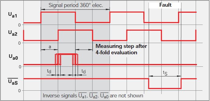
Now, I want to count the 4 edges in order to translate the 2 signals in the distance. This means that I need advanced two counters for Rising-rising, Rising-Falling Falling Falling, falling on the rise for 2 signals. I tried to do 4 points two counters in LabVIEW but that of course does not work, because an acquisition of data can access the card TTL or I did it wrong.
Once I have to handle this, I also want to understand the meaning.
My card TTL: NI 9402
My electronic Heidenhain interface: 100 IBV (http://www.heidenhain.com/fileadmin/pdb/media/img/598_160-23.pdf - also at the origin of the image)
Hardware configuration: linear scale-> IBV (Elektronic Interface)-> NI 9402-> LabVIEW
Signals: Analog 3-> 3 TTL-> OR 9402
I hope I do not double post. Any help would be greatly appreciated.
I used Heidenhain linear scales in many applications.
As stated in the previous post, the output of your balance is as a quadrature encoder. Therefore, you must use an entry of the DAQ card counter to measure the position of the scale.
The desired X 4 mode is done by the meter itself (not possible with some old maps of OR).
As starting point, see measure angular Position.vi that comes with examples of LabVIEW. On your linear scale, change the type of the polymorphic DAQmx create channel VI CI linear encoder and etiquette of pulses per revolution at a Distance by pulse.
Feel free to post back if you need further assistance.
Tags: NI Software
Similar Questions
-
How to count the edges within the great period of door?
Hello
I use a PXI-6624 counter/timer in Visual Studio C++ with Meassurment Studio.
I want to count the edges on a signal within a high period of an input signal.
I found the documentation entries "CTR n CBC", "CTR n GATE" and "CTR n to THE.My idea is simply configure the counter 0 to count the edges on CBC by blocking via DOOR.
can be an example to my problem in the installation of nor, but above all I do not understand the description of landscaping.
to find a good example, you must know the name of the function you want to use.
can someone tell me the good examplename for my problem?
What call configuration should I use?a little less important than my first problem is a similar.
I want to count the edges on a signal between a start trigger and a relaxing stop.
SRC-> signal
DOOR-> start signal
To THE-> the stop signalI found a way to count the edges of the internal clock between start and stop (2 Seperation of edge), but not for an external signal.
can someone help me with this? especially with the first.
B
Hi John,.
Thank you for your help. It works very well.
I had a few problems with how the timebaseSource should be implemented.
Finally, I found the solution.
for those who do not want to search long for the code, it is here:
Create the task
CNiDAQmxTask ("CITask") m_task;Create the meter inlet channel
m_task. CIChannels.CreatePulseWidthChannel ("PXI1Slot16/ctr0", "",)
atof (minimum), atof (maximum), startingEdge,
DAQmxCIPulseWidthUnitsTicks);Retrieve the channel to change
CNiDAQmxCIChannel chan is m_task. CIChannels.GetAll ();
Fix the DOOR Signal
Chan. SetPulseWidthTerminal("/PXI1Slot16/PFI38");The value of the Signal SOURCE counton
Chan. CounterTimebaseSource = ' / PXI1Slot16/PFI39 ";CNiDAQmxCounterReader myCounterReader (m_task. Stream);
Double measuredWidth = myCounterReader.ReadSingleSampleDouble ();Thank you and goodbye
B
-
Count the number of rising edges in table 1 d
Hello
I wanted to measure the frequency of a pulse signal using a MCC DAQ via libraries ULx in Labview. I have two methods to do this:
1. use the analog inputs:
Since data acquisition has only 1 ADC, I use a commune VI acquisition for all channels and create a multi-dimensional array with different channels in rows 0-15. Then divide them by using the function "Array Index". I think this split removes the parameter 'time' to the wave, since it is now a table 1 d. But I already know that there will be 1000 samples each 100 m everything I want to do now is to count rising edges using a function and divide it by the 0.1 to obtain the frequency in Hz, but I don't know how. Can anyone help?
2. use the input frequency meter:
Because I can't use the DAQ assistant, I have to use the CI frequency-> counter 1ChanNSamp DBL 1 d in the ULx library. There is no reference to take aid to and I do not know if this method is good. I have no way of knowing since I do not have a signal generator. In addition, it does not work so far.
Help, please.
Thank you!
Thank you.
I note in your first post it is seems to want to get readings of speed about 10 times per second. To get a resolution of 1 Hz frequency direct count you need to get at least 2500 counts in a range of counting at the highest frequency. This means that you need to have at least a second. Measures of the time are another option.
Some preliminary calculations:
Period at 2500 RPM = 2500 Hz is 400,000 Americans.
Period at 2499 RPM = 2499 Hz is 400,160 to the United States.
You need to be able to resolve a difference of 160 ns period. To do this directly requires 6.25 MHz sampling rate. It is 25 times faster that your DAQ card can enjoy.
What other options are there? Consider only your Information.vi extract. He uses techniques of Fourier transformation and interpolation to find the frequency of a signal. I set up a quick test VI to check this. Using a sampling rate of 10 kech. / s and 1000 samples per read (10 reads per second), it has easily resolution of less than 0.1 Hz at both ends of the range of speed and largely independent of the amplitude. This is the way to go.
Lynn
-
How to count the number of edges using counters SMU-6363
Hello
I'm counting the number of edges in a test signal in a duration of 50 Ms I use the SMU-6363 map and connect to the TRC test signals 0 SRC (PFI 8). Is that a correct connection? What else do I need hardware wise be a correct set for this application?
Thank you
Jeet
Hi Jeet,
This configuration is correct. Hardware wise, that's all you need to do.
Kind regards
Jorge Fernandez
Technical sales engineer
National Instruments
____________________________________________
Certified LabVIEW Associate Developer (CLAD) -
Count the number of 1 is present in digital waveforms obtained by converting the pulse signals.
Hello
I use Analogtodigital.Vi to convert the pulse of the sequences in digital.signals.I am able to get the representation of digital waveforms of impulses.
But how to count the number of 1 is present in the converted digital waveform. I want to count the number of 1 is present in the digital waveform converted.
Thanks in advance.
Have you tried the block scheme of similar to the Digital.vi of opening?
It creates an array 2D uncompressed 1 and 0, which is the binary 16 bits A/D conversion of each element in the array Y of the input waveform. You can use the DWDT digital Array.vi Boolean to convert a 2D Boolean table. Then convert Boolean values to 1.0 and summarize the array of integers. The sum must be the number of 1 bits in the digital waveforms.
Lynn
Note: The VI attached is saved in version 8.6. When I have it saved for the previous Version a warning was generated about the possible differences in the versions. Let me know if it doesn't work, and you are using which version of LV.
-
Generation of the trigger (or TTL) analog signal
Hello world
Well I look at the droplet, riding on the vibrating bath. In this case I have to synchronize the device with the accelerometers.
Accelerometers are connected to the vibrating plate vibrating sinusoidal with frequency of 80 Hz. I am the acquisition of acceleration using NOR-DAQ USB 6212. A camera (Camera Link Basler, NI PCIe-1433) is used to acquire images of the vibrating plate. The frame rate of the camera is 20 Hz which controlled by external signal (TTL) or camera attributes.
I would like to generate a trigger of data acquisition (signal HAVE) to the camera at the first minimum acceleration in the attachment. I've also attached the file vi. Could if it you please let me know if is there anyway we can generate the trigger of the analog signal.
See you soon
NGO
Hello, NGO,
Can you post the update VI?
-
Problem with signals TTL metering: confused with counting
Hello
I use a TTL of 0.2 Hz signal to synchronize two devices. I use a Usb-6210 card to count the pulses TTL. The meter goes off when it detects the edges increase. In my case, the meter was sometimes triggered at low altitude, which causes wrong results (see attached pictures, the TTL signal is sampled at 20 Hz and the dots represent an increment of the counter). How can I solve this problem?
In addition, the cable that connects the TTL output was welded by myself, would that be a problem of bad contact?
Thank you very much
K-X
What is the nature of the device producing the TTL trigger signal? Is it possible, for example, that it could produce a 1 microsecond pulse (which might not be visible on your signal ground) that would trigger the meter? You really produce a digital pulse (i.e. your something circuit which is 'on' or 'off' as opposed to 'product analog voltage in the range of 0 to 5 volts')? Are there any other devices around that could produce the impulses that are "picked up" by your meter? The cable connecting the TTL is armored pulse for the meter? The shield is based at one end?
These questions (and the previous) suggest that the problem may be 'electronic' rather than 'LabVIEW '...
-
Change the shape of the output signal without initializing the new process of output signal
Hello!
How to change the shape of the output signal produced on the output channel without initializing the new process of output signal?
Thank you
Yes, you can do the same thing without count/killing the task all the time.
Attached VI shows how to use redeclenchables AO in the same way, using a meter like time base for the AO.
Please note that attached VI uses the same Subvi as in the example you posted before.
Christian
-
FPGA: the internal signals in ModelSim display
I have a piece of code written LabVIEW FPGA in that I am trying to simulate in ModelSim. I followed the instructions in this link, but the example is a simple incrementer with no internal signal (only the input and output).
I created a test bench and started the simulation, but the macro provided .do only adds the entries and exits to the wave window. ModelSIM lists pages and pages of processes and signals that can be added to the waveform window; all have names completely opaque. I found something called 'TheWindow', and then a subdirectory called "Thatcher" and added all these signals to the waveform window. The names are things like ResHolder00000000000001 and provide no information on where they came from.
I tried to assign labels to the sons of my LabVIEW diagram, but that did not help at all in creating useful names. I need to check the progress of States in my VI but can't find anything that seems like the appropriate signal. A lot of available under 'Thatcher' waveforms are waveforms static, uninitialized, or both. How can I assign names to internal signals so that the waveforms are actually intelligible?
On a side note, it is also a problem in the synthesizer. I'm used to using the synthesizer output to 'pre-debug"my code, but LabVIEW seems to ignore the process of inference any macro. I tried to put a SCTL with an incrementer and LabVIEW does not infer a counter. I have never seen one of my machines of State recognized in the synthesizer, even if the code works correctly.
Using ModelSim PE 10.3, I understand is not "officially supported", but the fact that the synthesizer and the Simulator have the same denomination made problem wants me eliminate this as a problem. I do not use one of the PE extensions on the version SE.
Hi Nick,
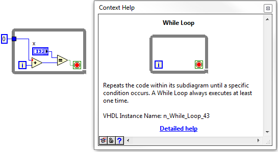
If it is not the most readable, its not too hard to find signals that you are looking for. Your biggest help will be context-sensitive help in LabVIEW. If you hover over the structures, nodes, or son, in your LabVIEW FPGA design, at the bottom of the help context window, you'll see what we call the 'name of the VHDL Instance".
Once you navigate through the hierarchy down through the window, in the VI, you should start to see some of your top-level objects, such as while loops etc. From there, you can navigate down in whatever the level and find the wire you are looking for.
I did not have the ModelSIM on my machine, but it works for the ISIM. I wish they had a search function, so you can just type in the signal you are looking for.
-
Hello
Installation program:
2 x PCI-6602
Configuration:
Sampling the five PWM signals of 50 kHz using five counters (2 on a map) and three on another for about 10-15 seconds by recording continuously.
All meter tasks are configured for DMA transfer.
Problem:
I get 200141 errors from time to time.
Question:
I tried to increase the size of buffer and all tasks of meter are set to DMA. In the error message the last suggestion is to "divide the input signal before taking the action. I don't understand this suggestion. What is meant by "split the signal before taking the action?
I am open to other solutions to the problem.
/Mola
Yes, I know that the 2 MB/s sound do not like much, but it's a way of high load very low tolerance to try to get 2 MB/s. You have 5 DMA controllers to negotiate access to the bus and each transmits only 1 or 2 samples of 32-bit whenever he gets access.
I've seen published baseline data where the maximum sustained rate was< 1="" million/sec="" (don't="" recall="" if="" it="" was="" mbytes="" or="" msamples). ="" as="" i="" recall,="" finite="" acquisition="" mode="" allowed="" higher="" rates="" for="" shorter="">
Ah yes, here is a link that leads to the other links. See the section on "The counter of the FIFO" in the first message. Do you see a * very * significant difference in the performance of the M series for the series X-series. Here are data for counters of the E series. (It is fair to note that the comparative analysis was conducted with a much older PC hardware). For the 6602 counter chip was designed between E- and M-series series, so you can probably expect performance in-between.
Also note that the benchmarks seem to have been done with a task of window unique tent of owning all the bandwidth PCI as possible. Since you would have 5 tasks they negotiate access, you lose definitely even more overhead. In addition, for fair comparisons, your 50 kHz PWM would act as a measure of 100 kHz since you have 2 semiperiods to DAB per cycle of 50 kHz.
Now that I've seen benchmarks once again, I am convinced that it is a no-go for you with just the 6602. The good news is that the series X-series seem able to yet more ridiculously than I remembered.
-Kevin P
-
How can I count the pulses in a channel?
Hello
I have a channel consisting of 0 and 1 (data comes from a proximity sensor) and I was wondering if there is an easy way to count the events (i.e. pulse) to (Advanced) Tiara? At its simplest, I just need a method to count the number of rising edges in the channel.
A script would be the way to do this? If so, is there any example autour code to demonstrate how to analyse the lines in a channel?
Thank you
PorridgeMan.
Hello!
@Martin: IMHO your aproach can operate, but need not because of input data and the right compares value (10 in your case).
If the input data are not a pure 0-1 step you can get more the a value greater than 10 for a rising edge.
The comparison value depends on the distance of time and the channel values, and it's not easy to calculate in advance.
The other drawback I see is that you need a channel of X, which is not really necessary to solve the problem.I think my code will be more robust (IMHO as I mentioned).
@PorridgeMan: Yes, it's a shame it takes certain steps of DIAdem to solve this common problem.
First: By script is possible, but generally to slow down. My approach is to insert a 0 value at the beginning
a copy of the input channel table and compare it to the input string. If a value is less than 0,5 (half of you maximum values)
and the other is higher I put a 1 0 otherwise in a result string. Even in more complicated cases, the comparison value could
be calculated or alienated by a moving average.
Here is the code:
Option Explicit

' Copy data
Call ChnCalculate("Ch(""[1]/Dif"")=Ch(""[1]/Pulses"")")
' Insert one 0 at the beginning
Call DataBlInsertVal("[1]/Dif",1,1,0,0)
' Compare and convert result to 1 or 0
Call ChnCalculate("Ch(""[1]/Result"") = IIf((Ch(""[1]/Pulses"") < 0.5) And (Ch(""[1]/Dif"") > 0.5), 1, 0)")
' Sum is result
Call MsgBox(Cch("[1]/Result",4))
Hope this helps
Matthias
-
Hi all
I am a new user of LabVIEW and I'm going to ask you about a problem that certainly many of you will find quite annoying.
I develop software for a test machine management that uses an another bend, a tachometer that generates a signal of rectangular analog output in volts, 0V to 8V. Like many I thi signal in a waveform graph.
My goal is to be able to count the number of cycles of the machine and power count the tension peaks and subsequently be able to work on the machine with respect to the number of rounds to make. the ultimate goal is to be able to tell the machine how many rounds/cycles to do and the voltage applied to the load cell.
Would you be able to give me some advice on this subject? Especially about count and store the number of revolutions.
If necessary, I could send a screenshot of the program.
I tried to use a crest of the threshold detector but I'm still inexperienced, it's why I ask for your help.
can someone help me?
Thanks in advance.
Greetings
LV
Look at the detection of peaks VI and examples (help-> find examples).
It should be fairly easy to understand and implement

-
How to count the pulses with digital input on 6351
Hi all experts in Labview,.
I just got my USB x series 6351 and it works fine, but I certainly lack of labview skills to use it to its full potential.
I would like to read digital pulses with several digital inputs and count the number of pulses each T interval in time. All impulses that I entered on any edge of the clock are not synchronized and can occur at random times during the tests. Basically I have an oscillator of square waves can I modulate the frequency. I don't want to use the meter as inputs as I'm limited to only 2 entries (if I use the option 2 input meter for metering of pulses or frequency). The input frequency can range from 0-1 kHz and goes 0 - 3V. So not too fast, and I shouldn't make too many mistakes trying to get the count of pulses and then back out the frequency in accordance with article ni.com on counters.
I would like to read the 8 digital input channels and get the number of impulses for each channel. I searched high and low for help online but can't find examples that have been useful. Anyone have any ideas on how to go or direct me to a resource? Thank you very much in advance!
Are you worried about getting the number as a physical operation timed? It would be nice to acquire a digital waveform and then postprocess on it to detect how many events took place? I've attached an example that shows how you can accomplish this. It reads a digital waveform and then uses a detection of crete VI to determine how many pulses occurred. Should be a few adjustments to your particular signal. The VI I use seems to count events twice (probably count each edge), so counting it gives should be reduced by half in order to work.
-
read the analog signal 0-10 volts of NI6123
I'm reading the analog signal of NI 6123. The range of the analog signal is 0 to 10 volts. This works well when the signal voltage is 0 to 5v (0 ~ 32767). But when the signal is 5 to 10 volts, the value read is always 32767. I also tried the different reading function: DAQmxReadBinaryI32, DAQmxReadBinaryU16, DAQmxReadBinaryU32. The value is identical to DAQmxReadBinaryI16. My OS is windows vista. Here's the part of my codes.
**************************************************************************************************************************************************************************
Create analog data tasks.
DAQmxErrChk (DAQmxCreateTask("",&datHandler));
DAQmxErrChk (DAQmxCreateAIVoltageChan(datHandler,"Dev1/ai0:7","",DAQmx_Val_Cfg_Default,-10,10,DAQmx_Val_Volts,NULL));)
DAQmxErrChk (DAQmxCfgSampClkTiming(datHandler,"",RATE,DAQmx_Val_Rising,DAQmx_Val_ContSamps,RATE*MAXLAS));
DAQmxErrChk (GetTerminalNameWithDevPrefix(datHandler,"ai/SampleClock",trigName));
Create counter tasks.
DAQmxErrChk (DAQmxCreateTask("",&ctrHandler));
DAQmxErrChk (DAQmxCreateCICountEdgesChan(ctrHandler,"Dev1/ctr1","",DAQmx_Val_Rising,0,DAQmx_Val_ExtControlled));
DAQmxErrChk (DAQmxCfgSampClkTiming(ctrHandler,trigName,RATE,DAQmx_Val_Rising,DAQmx_Val_ContSamps,RATE));
DAQmxErrChk (DAQmxRegisterEveryNSamplesEvent (datHandler, DAQmx_Val_Acquired_Into_Buffer, SPLEEN, 0, EveryNCallback, NULL));
DAQmxErrChk (DAQmxRegisterDoneEvent(datHandler,0,DoneCallback,));
Start the task.
DAQmxErrChk (DAQmxStartTask (ctrHandler));
DAQmxErrChk (DAQmxStartTask (datHandler));
In the call back function:
DAQmxErrChk (DAQmxReadBinaryI16 (datHandler, SPLEEN, 3.0, DAQmx_Val_GroupByChannel, data.laser, MISS * MAXLAS, & (data.dataRead), NULL));
DAQmxErrChk (DAQmxReadCounterU32 (ctrHandler, SPLEEN, 3.0, data.counter, SPLEEN, & (data.ctrRead), NULL));
write data to the file.
data.cfile.Write (data.counter, sizeof (int32) * RATE);
data.cfile.Write (data.laser, sizeof (int16) * RATE * MAXLAS);
**************************************************************************************************************************************************************************
Thanks in advance
To make sure that your device is working properly, I recommend first to test the entry in measurement and Automation Explorer (MAX) analog. You can test your device by right clicking on it in the configuration tree and selecting test panels. See if you acquired signal 0 - 10V as you expect. The next step would be to try one of the sample programs that perform a task of analog input. These examples can be found in the start menu > programs > National Instruments > NOR-DAQ > text based code supported. Try an example that does an analog input continues and double bed (instead of binary data not adjusted).
Your program looks good at first so I found nothing that stood out. However, one thing to check is if your function generator (or signal source) expects a 50 ohm or high impedance. This could cause reflections of the signal and cause the device to possibly read a voltage of half of the desired value.
-
class.h file not recognized by the compiler signals section
Hey. My class .h file is pasted below with a screenshot. The signals keyword is cyan, when I think it should be purple. Also when I mouse over the word he said Macro Expansion (protected) (even though the words of Macro are green).
I don't think that the compiler is grateful signals: article because the signal that he is apparently not defined.
Appreciate any help,
Justin.
/*
 * Count.h
 *
 *  Created on: 23/03/2015
 *      Author: Justin
 */

#ifndef COUNT_H_
#define COUNT_H_

#include

    class Count : public QObject
    {
        Q_OBJECT
        Q_PROPERTY(int downloadedDataSinceStart READ downloadedData WRITE setDownloadedData NOTIFY downloadChanged)

    public:
        Count(QObject* parent = 0);
        virtual ~Count();

        int downloadedData();
        void setDownloadedData(int data);

    signals:

        void downloadChanged();

    private:

        int m_data; // The data downloaded in Mb

    };

#endif /* COUNT_H_ */
Screenshot:
downloadChanged() is a signal and should not be reported as a RPC function, which means that you must delete these lines (sorry for the formatting):
{} void County: downloadChange()
//...
}If you want to run code when the downloadChange() signal is displayed, you must connect a machine slot to this signal, run the code in the slot (ie: onDownloadChanged())
See here for more info about the signals and slots:
http://developer.BlackBerry.com/native/documentation/Cascades/dev/signals_slots/

Maybe you are looking for
-
How can I fix a white screen on the ipad look like?
My iPad Air was an itunes movie download. As it progressed, the screen is blank. I tried all the measures available in HT201263 without result. iTunes on my PC habit recognize it at all, but it recognizes other devices. When plugged into the PC a
-
Please delete my Skype account!
-
Satellite M40-192 - Download Driver
Hello! First of all, sorry for my bad English. I have the following problem and ask for your help: I need updated to my NB Satellite M40 192 drivers. Unfortunately this isn't me, even to a list of drivers available with Toshiba to come.If I was here
-
Failed to install driver Officejet 8610 on Windows 8
I'm trying to install the driver on my HP ENVY laptop, but the keeps installation not. This is a new printer and my HP laptop is newer by using the system of 64-bit Windows 8... THX...