Problem with signals TTL metering: confused with counting
Hello
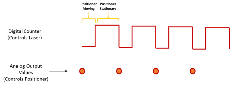
I use a TTL of 0.2 Hz signal to synchronize two devices. I use a Usb-6210 card to count the pulses TTL. The meter goes off when it detects the edges increase. In my case, the meter was sometimes triggered at low altitude, which causes wrong results (see attached pictures, the TTL signal is sampled at 20 Hz and the dots represent an increment of the counter). How can I solve this problem?
In addition, the cable that connects the TTL output was welded by myself, would that be a problem of bad contact?
Thank you very much
K-X
What is the nature of the device producing the TTL trigger signal? Is it possible, for example, that it could produce a 1 microsecond pulse (which might not be visible on your signal ground) that would trigger the meter? You really produce a digital pulse (i.e. your something circuit which is 'on' or 'off' as opposed to 'product analog voltage in the range of 0 to 5 volts')? Are there any other devices around that could produce the impulses that are "picked up" by your meter? The cable connecting the TTL is armored pulse for the meter? The shield is based at one end?
These questions (and the previous) suggest that the problem may be 'electronic' rather than 'LabVIEW '...
Tags: NI Software
Similar Questions
-
I am a new user of Labview, so it's a little intimidating. I am using a cDAQ-9188 with several modules but I have problems with one is the 9411 is used to measure the speed off the coast of a torque meter.
I joined the program I put in place. What I want to do is to measure the number of edges on a 3 second interval so that I can divide by the number of pulses/turn * 60 * 1/3 to receive the RPM. However, the number of edges behave linearly as I expected. I measured the speed of the shaft with a light strobe and represented graphically it vs the number of edges. The results are attached to the excel file.
What Miss me? The number of edges should not increase as speed up the tree, or I'm going about this all wrong and is not what I think I am?
Thanks in advance.
Ahh ok, that make more sense - it seemed like a strange to report a couple measured, way but now I understand that your torque sensor also rpm through this collection of speed option and that's what you ask the subject (I can't see not how pulses/turn the sensor is on the site Web of Honeywell however, do you know offhand?).
The software timing 3 seconds will implement much of the variability in your measure but would not explain the strong negative correlation between the RPM and the speed sensor (we're talking several ms of non-determinisme for a second window 3) output frequency. Finally, you'll want to solve this problem as well, but it is not your problem right now (as an aside - it would be actually more accurate to measure the frequency of the signal encoder using the 80 MHz as a reference time base and average the result on a second window 3, the general idea is sort explained in manual of 9188 here but I digress).
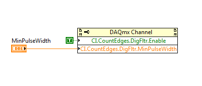
I think it is more likely that the signal from the speed sensor is a bit noisy (pretty typical of optical encoders) and then transitions the 9411 is picking up multiple edges. A slower RPM equals longer transitions and therefore more false edges. It is just a hunch, but that's what I can think of on the top of my head that could be causing what you see (if read number of pulses is higher than what you expect, given the pulses/turn of the sensor through all ranges of RPM that it would support my theory). If you want to ignore the method of measurement for a second and try to solve the problem of noise (assuming there is one), you can add the following property node to your existing code before you begin the task:
You can start by setting MinPulseWidth to 6.4us (which is one of the built-in clock dividers available for PFI filters on the 9188). You want the MinPulseWidth be short enough to ensure detection of a legitimate impulse, but long enough to block all wrong edges that occur during transitions.
Best regards
-
Problem with Counter strike 1.6 on Vista
When I run my CS on vista, suddenly an unrecoverable error message on the screen that says "the available memory is less than 15MG!:-some figures.
What should I do?Hi KiwiSwat,
Please use the Forum of responses of Microsoft Windows Vista.
It seems that this problem with CS has been resolved by running it in Windows Xp compatiability mode.
Right-click on the shortcut, choose Properties, compatibility, mark the run this program in
compatibility mode for: choose Windows XP SP2.
You can also check the below CS forum that talks about the same mistake and was fixed by
Try the above steps
http://forums.counter-strike.com/counter-strike-1-6/7601-error-available-memory-less-than-15-MB.html
Please let us know if that helps.--------------------------------------------------------------------------------
Nicolas Mathieu
Microsoft Answers Support Engineer -
Problem with counting function, passing VARs between functions.
Hi guys, I have a problem with this section of code...
Could anyone suggest how to fix the function at the bottom so that when the button forward_btn with label "go to next Point training" when you click on recalculate the fields created in the function fileLoaded
var xmlData:XML = new XML ();
var theURL_ur:URLRequest = new URLRequest ("xml.xml");
var loader_ul:URLLoader = new URLLoader (theURL_ur);
var more: RegExp = / \ + / g;
var t:Number = 0;
var tmax:Number = 0;loader_ul.addEventListener ("complete", fileLoaded);
function fileLoaded(e:Event):void {}
xmlData = XML (loader_ul.data);
Tmax = xmlData.Record.length ();
trace (tmax);trace (unescape (xmlData));
trace (xmlData.Record.length ());
var title_tp:String = unescape(xmlData.Record.TP.Title[t]).replace (, "");
Title_TP_txt. Text = title_tp;var intro_tp:String = unescape(xmlData.Record.TP.Introduction[t]).replace (, "");
Intro_TP_txt. Text = intro_tp;
static_tp_intro.y = Title_TP_txt.y + Title_TP_txt.textHeight + 10;
Intro_TP_txt.y = sta_tp_intro.y + sta_tp_intro.textHeight + 5;
Title_TP_txt. AutoSize = TextFieldAutoSize.LEFT;
Intro_TP_txt. AutoSize = TextFieldAutoSize.LEFT;
}forward_btn.label = "go to the next Point training";
forward_btn.addEventListener (MouseEvent.CLICK, next_if);function next_if (me: MouseEvent): void {}
If (t == tmax) {play(); }
else {t = t + 1;
fileLoaded () ;}
}I don't see where you have a question from vars between functions because you do not pass everything. Maybe that's your problem. The function fileLoaded expects an argument, but you are not providing one. To get around that you should provide any argument being sent in the first function...
function fileLoaded(e:Event=null):void {}
Another option would be to separate features and put a quick end to the function fileLoaded and create another function that holds the rest of the code...
function fileLoaded(e:Event):void {}
xmlData = XML (loader_ul.data);
Tmax = xmlData.Record.length ();processXMLData();
}
function processXMLData (): void {}
trace (tmax);trace (unescape (xmlData));
trace (xmlData.Record.length ());var title_tp:String = unescape(xmlData.Record.TP.Title[t]).replace (, "");
Title_TP_txt. Text = title_tp;var intro_tp:String = unescape(xmlData.Record.TP.Introduction[t]).replace (, "");
Intro_TP_txt. Text = intro_tp;
static_tp_intro.y = Title_TP_txt.y + Title_TP_txt.textHeight + 10;
Intro_TP_txt.y = sta_tp_intro.y + sta_tp_intro.textHeight + 5;
Title_TP_txt. AutoSize = TextFieldAutoSize.LEFT;
Intro_TP_txt. AutoSize = TextFieldAutoSize.LEFT;
}forward_btn.label = "go to the next Point training";
forward_btn.addEventListener (MouseEvent.CLICK, next_if);function next_if (me: MouseEvent): void {}
If (t == tmax) {}
Play();
} else {}
t = t + 1;
processXMLData();}
} -
I found this function
SELECT
TRUNC (86400 *(date_to-date_from))-60 * (trunc ((86400 *(date_to-date_from)) / 60));
TRUNC ((86400 *(date_to-date_from)) / 60)-60 * (trunc (((86400 *(date_to-date_from)) / 60) / 60));
TRUNC (((86400 *(date_to-date_from)) / 60) / 60)-24 * (trunc (((86400 *(date_to-date_from)) / 60) / 60) / 24)),
TRUNC (((86400 *(date_to-date_from)) / 60) / 60) / 24)
IN tempsSec, tempsMin, timeHr, heureDAY
FROM DUAL;
Nice and easy compare two dates and return the (time) difference as 13 hours, 40 minutes, 10seconds
now, my system shows delays like this from 10:00 to 10:19 (which is the duration of 9 seconds if you use the function above).
now, what I tried to do is to add 1 second of time, since there are between 10:00 and 10:19 actuially 10 seconds elaps (0 to 1 (1 second), 1-2 (1 second)...)
so I tried to just add a seconds before the date_to
SELECT date_to + 1/24/60/60 INTO date_to FROM DUAL; -Add a second because 00 09 is 10 seconds of display time (not 9!)
but sometimes, this provides a valid information, sometimes when counting only seconds each presents a wrong time, so there is an obvious mistake, I do somewhere...Rather than trying to debug the code you posted, it is probably easier to convert dates to timestamp, subtract the timestamps whiich returns an interval and extract the components of the interval.
Note that I add 1 second in the inline query. For the subtraction normal timestamp, you who would remove.
SQL> ed
Wrote file afiedt.buf

  1  with x as (
  2    select to_date( '10/24/2009 10:05:10',
  3                    'MM/DD/YYYY HH24:MI:SS' ) date_from,
  4           to_date( '10/24/2009 14:55:19',
  5                    'MM/DD/YYYY HH24:MI:SS' ) date_to
  6      from dual
  7    union all
  8    select to_date( '10/24/2009 10:05:10',
  9                    'MM/DD/YYYY HH24:MI:SS' ) date_from,
 10           to_date( '10/24/2009 10:05:29',
 11                    'MM/DD/YYYY HH24:MI:SS' ) date_to
 12      from dual
 13  )
 14  SELECT extract( day    from interval ) days,
 15         extract( hour   from interval ) hours,
 16         extract( minute from interval ) mins,
 17         extract( second from interval ) secs
 18    from (
 19  SELECT  to_timestamp(to_char(date_to,'MM/DD/YYYY HH24:MI:SS'),
 20                       'MM/DD/YYYY HH24:MI:SS')
 21          + interval '1' second
 22          - to_timestamp(to_char(date_from,'MM/DD/YYYY HH24:MI:SS'),
 23                       'MM/DD/YYYY HH24:MI:SS') interval
 24  FROM x
 25* )
SQL> /

      DAYS      HOURS       MINS       SECS
---------- ---------- ---------- ----------
         0          4         50         10
         0          0          0         20
Justin
-
Problem of IR with COUNT (*) (AS apxws_row_cnt)
Hello world
I use the same question raised in the IR problem with COUNT (*) () AS apxws_row_cnt discussion Forum, by Marco 1975. I'm developing on APEX 5.0.0.0.31 and using the Oracle 12 c DB. An IR translates 4648 occurrences only 100 records. The SQL is okay, but the OVER() COUNT (*) AS apxws_row_cnt done something witcthery on my report. Anyone has any idea how to solve this problem in 5 APEX?
My query:
SELECT PK_EMPLOYEE,
DATE_HIRE,
DATE_QUIT,
DBMS_LOB. GetLength ("foto") "FOTO"
NAME,
CPF
OF TB_EMPLOYEE
I found, helped by 3rd party experts - CITS Brasília - workaround using nested selects to avoid the Cartesian product of my request on IR. This is a Cartesian product of column FOTO ("PHOTO") against a column of master FK from another TABLE.
In any case there is the solution, I'm sorry for the Portuguese terms, but I understand that it will be quite understandable:
SELECT DISTINCT NULL as apxws_row_pk, "PK_EMPREGADO", "CPF", "NAME", "FOTO", "DATA_CONTRATACAO", "DATA_DISPENSA", count (*) (as apxws_row_cnt)
FROM (SELECT * FROM ())
SELECT
b."PK_EMPREGADO."
----------------------------------------------------------
--> Cartesian product: PHOTOS N versus Post - Posto Trabalho work 01
-"FK_POSTOS_TRABALHO"
-------------------------------------------------------------
-nvl (L1. ("" "' DISPLAY_VALUE ', b." FK_POSTOS_TRABALHO ") as"FK_POSTOS_TRABALHO,"
------------------------------------------------------------
«"" "" "" b."FCP", b."NOME", b. "FOTO", b. ' DATA_CONTRATACAO ', b. "DATA_DISPENSA»
FROM (SELECT * FROM (select distinct emp.) PK_EMPREGADO, emp. FK_POSTOS_TRABALHO, emp. FCP, emp. DATA_CONTRATACAO, emp. DATA_DISPENSA, emp. NOME, dbms_lob.getlength (emp. FOTO) "FOTO".
OF TB_EMPREGADO emp
RIGHT JOIN TB_POSTOS_TRABALHO_HOM pt ON (pt. PK_POSTOS_TRABALHO = emp. FK_POSTOS_TRABALHO)
TB_EXECUTORES of RIGHT JOIN ex WE: APP_USER IS NOT NULL and: APP_USER = e.g. MATRICULA AND pt. FK_CONTRATADA = e.g. FK_CONTRATADA WHERE emp.cpf IS NOT NULL
) ) b,
(SELECT NUM_CONTRATO |) ' - ' || DESCRIPTION as display_value, FK_POSTOS_TRABALHO as return_value
OF terceirizado. TB_CONTRATADA cont, terceirizado. Post TB_POSTOS_TRABALHO_HOM, terceirizado. Tipo TB_TIPO_HOM, terceirizado. TB_EMPREGADO emp
WHERE to post. TYPE = type. PK_TIPO and cont. PK_CONTRATADA = post. FK_CONTRATADA and emp. FK_POSTOS_TRABALHO = post. PK_POSTOS_TRABALHO
L1 OF THE ORDER OF 1)))
I hope that Oracle will provide a coherent solution for COUNT (*) () AS apxws_row_cnt question.
-
Error: 200279. Problems with playback of three signals with NI 9234
I try to read three signals at the same time with the NI 9234. But I have the problem with the buffer, I have read about this error and tried all the solution they gave (sample of Crescent by channel, increasing the number of samples per channel or decrease rate) but still nothing. I also try architecture design of producer/consumer model, but nothing, it always get this error. Someone knows how to fix this?
lincoln1991 wrote:
Well, I realized that the error only occurred when I was to "highlight the execution", it's wear and tear
So problem solved. Now you know why.
-
Problems with signal followed during sampling of the signal
Hello
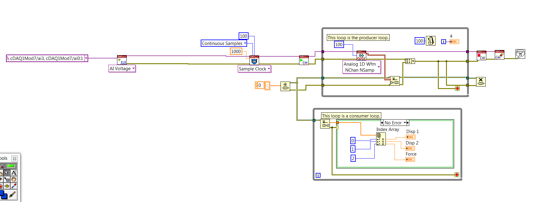
I'm relatively new to LabVIEW 8.0 and I'm having a problem with being able to monitor the signals that I am gaining two simultaneous analog signals. I have the user to input the frequency of sampling and the length of the sample, and then I starts the scan, but when running the analysis, I don't see no result on the chart if the duration of the sample is passed, at which point all data comes. Previously, I could see the acquisition of real-time data and I don't know what I've done since then have possibly that stop working. I tried to introduce a kind of late for may allow the software to apply the data to the graphics, but I had no success.
I have attached the VI of the data acquisition component.
Thank you so much for reading this.
Hello
I suggest you try these two options:
1. in each iteration of the while loop, add your data to the data of the previous iteration, IE use a shift register to create an Adrien to data that you have acquired. When you save the data in a file, read data from the table and not the current value of the waveform. You can read the data in the table by using a queue, or by using any simple method to pass data between the blocks.
When you use a local variable of the waveform card, you only read the current value in the array, not its history.
2. use a property of waveform graphs node to read the history of the ranking, convert the picture from picture to picture 1 d 2D using cluster of waveform ungroup functions and write to the file, click on "Save".
-
[FPGA] Problem with the sinusoidal signal generator
Hello!
At first I want to apologize for my English is not my mother tongue.
Hardware and software I use is:
LabVIEW 8.5
NEITHER RIO 2.4.1
NEITHER cRIO-9014 (controller in time real CompactRIO)
NEITHER cRIO-9104 (chassis and FPGA)
NEITHER 9264 (16 channels, +-10V, 16-bit voltage analogue output Module)
I made a very simple FPGA VI: a while loop, generator of sinusoidal signal and a FPGA of e/s node in the loop. I've specified the Gnerator settings by following the path:
Frequency = 50 Hz
Amplitude = 1
Phase shift = 0.00
Size of the table look-up = 1024
= 16-bit amplitude resolutionFPGA clock frequency (40 MHz)
But the wave of "sine" I got is not what I wanted to get. First of all, its amplitude is 1 V. shouldn't it be coded on 16 bits? If I wanted to get 1V I should have specified Amplitude as a 3277. In addition, 'sine' is not very detailed, it's look like "steps", as many samples vere missing. What I did wrong? I checked the samples and tutorials, I did everything the same way. A I forgot something or not has not specify other parameters?
Thanks a lot for your help!
OK, I solved a problem. It's embarrassing to admit, but maybe this will help someone else
 I blame my inexperience
The main solution to the problem was changing calibration of calibrated RAW Mode. After that, everythoing works as expected. I had a problem with a sample because I was using a multiplier to control the generated sine wave amplitude. But... She was set to 1 in the sinusoidal signal generator. That was the reason for waveform Gradin. Please, don't laugh too much

In any case, thank you for an answer! It is now resolved
-
I am facing a problem with the beep.vi. I have a DAQ program, which acquired the signal and compare it to a threshold value. When a signal is out of range, a Visual and sound alarm has occurred. I use the VI beep.vi to generate the sound. Everything works fine except the sound alarm. It gives the table 1 d of type mismatch. I tried to fix this by placing it in a box structure. But it still does not work. If someone could help? Please find attached my VI. Best wishes to all visitors to the Forums of Discussion OR.
Ihab El-Sayed
published here: http://forums.ni.com/t5/LabVIEW/Playing-sound-based-on-exceeding-a-threshold-value-1D-array-data/m-p...
-
Hello, I have problem with my Sony z2 that I have weak signal mobile after update to new android 5.1.1 build number 23.4.A.1.264
Before the updates signal was better.
You can't unless you use flashtool or xperiafirm, or contact your Local support
If I were you, I would repair the phone with PCC
Bridge (for Mac)
Alternatives on how to backup Xperias
-
I have a problem with my Apple Watch, when I use the watch on my treadmill, keep the phone, the number of step does not appear, the whole market is a waste if it shows only not on Apple Watch, how to solve this problem?
Hi Shabbir
Apple Watch has two integrated health and fitness apps: enforcement activity and the application of the workout. For best results, make sure your arms naturally swings while walking on the treadmill, as Apple Watch uses movement of arm (measured by the built-in accelerometer) to track and evaluate movement for indoor activities. If you use the application of the training session, your watch will also measure your heart rate continuously for training in order to estimate the calories burned.
Check that you have configured the application of the activity:
-Press the rings activity on your watch dial or open the application for the activity (if you have not set it upwards, you will be prompted to answer a few questions).
Also, make sure that the fitness of tracking is enabled:
-On your iPhone, in the application of Eve, go to: Watch My > privacy > Motion & Fitness > fitness monitoring.
You can improve the accuracy of the estimates related to activity in calibrating Apple Watch (take your iPhone with you on walks outdoors or tracks, connected to your Apple Watch and with location enabled Services - see the detailed instructions in the article to support below).
More information:
http://www.Apple.com/watch/health-and-fitness/
Use the activity on your Apple Watch - Apple Support
Use of the workout on your Apple Watch - Apple Support
Calibrate your Apple Watch for better accuracy of training and activity - Apple Support
-
Problems with Atheros WLAN on Satellite L750D
Hello
I got the L750D SATELLITE with Atheros AR9002WB-1NG Wireless Network Adapter (with the latest driver), but this card has serious problems in the detection of signals transmitted by the router. With previous and other laptops that I never had problems with the connection to the internet, however my new laptop is forcing me to sit in an area of 4 meters around the router. How can I fix?
-check the latest driver updates
-re-installed the driver
-checked on the forums how to solve this problem
-tour of my bluetoothLooking forward to a response.
Greetings from the Netherlands.Is - this general problem with this laptop, or just when you use it on power electric battery?
Check the power settings for WLAN and place it on the option high performance. -
Analog output with counter Falling Edge
Hi all
Here's the iamge which describes what wishes to accomplish. I would like to trigger that the AO output with the edge of the fall of the meter.
I have set the clock for my AO as the counter.
The analogue output should be raised whenever the Digital signal meter falls
SAMPLE_SIZE = 80
SAMPLING_RATE = 40 #Samples are written every 25 milliseconds
TIME = float ((SAMPLE_SIZE) / (SAMPLING_RATE))CREATE TASKS
CREATE CHANNELS OF AO
CONFIGURE THE TIMING CHANNELS
DAQmxCfgSampClkTiming (taskHandleAO, "PFI12", SAMPLING_RATE, DAQmx_Val_Falling, DAQmx_Val_FiniteSamps, SAMPLE_SIZE)CREATE TASKS
CREATE A CHAIN COUNTER
# Time high-low + time equals 25 milliseconds and is proportional to the frequency of sampling
DAQmxCreateCOPulseChanTime(taskHandleD,"DAQ/ctr0","",DAQmx_Val_Seconds,DAQmx_Val_Low,0.00,0.005,0.020)# The values of voltage DAQmx writing
DAQmxWriteAnalogF64(taskHandleAO,SAMPLE_SIZE,0,10.0,DAQmx_Val_GroupByChannel,Voltage,None,None)# DAQmx AO task start
DAQmxStartTask (taskHandleAO)# Counter DAQmx Start task
DAQmxStartTask (taskHandleD)#TIME is equal to the total time for the writing samples
DAQmxWaitUntilTaskDone (taskHandleD, 2 * TIMES)I get an error every time that I run the task:
DAQError: Over Acquisition or generation has been stopped until the required number of samples were acquired or generated.

 function DAQmxStopTask
That's because my AO task is stopped for some reason any.
Is there an obvious problem with the code. Can it be structured differently?
best regards,
Ravi
I do all my programming in LabVIEW, so I'm pretty limited to help with programming syntax text. That being said, here's what I * think * I see:
Your AO task issues a call to DAQmxCfgSampClkTiming, but is not your task of counter. This probably leaves you with a meter spot which creates only a single impulse, which causes only a single AO D/A conversion. In LabVIEW when I need a pulse train, I would call a similar function of the synchronization with the clock mode is defined as 'implied '.
Hope this helps you get started, I don't know enough to give you the specific syntax in the text.
-Kevin P
-
Problems with encoder motor switching noise readings
Hi all
I wanted to ask advice with a hardware problem which seems to be pretty common.
Here I describe my request:
We are controlling an electric actuator for robotics application. We use encoders to take position readings, and we need to perform analog acquisition for other measures (for example, the force measured using strain gauges).
The problem is:
In summary, I have problems to properly acquire position readings of a linear encoders quadrature and also a few analog inputs. The cause is the switching noise generated by the drive motor that we use (which is an engine without Stricker of CC Moog BN-23-23).
Our acquisition platform is an NI PXI-8106 with a PXI-1042 q chassis. We have two possibilities to acquire the signals. We have a multifunction DAQ series NI PXI-6259 M and a FlexRIO NI PXI-7951R with one module DIO NI PXI-6581R.
The switching noise have a frequency of 30 kHz. In a scope, we see a series of peaks of noise which are present only during a short period of time (approximately 1/10th of the duration of the noise). The rest of the time the noise is not present.
The Accelnet amplification module that powers the electric motor gives us a clock signal synchronized with the noise (whose frequency is approximately 1/4 frequency noise). This clock signal provides a way to solve the problem of analog acquisition. We can use this clock to make an acquisition stamped with an external clock in LabView connecting the clock on a spit of PFI or FPGA card. But the noise is also corrupt this clock signal (we get an error daqmx us warning of possible defects in the clock signal and also to stop the acquisition). I believe that to solve the problem of encoder we can also solve the problem of the analog acquisition.
In the encoder readings noise makes our County to counter upward or backward gradually fast enough. We can get an increase in the position of about 10 cm per second with no appreciable movement in the linear actuator.
It would be a great help if someone could put the solution he uses to solve this problem.
Thanks in advance for your help,
jespestana
PS: I stress my conviction that we have a hardware problem, because we have only bad readings when the electric motor does not work. I am therefore convinced because we have already done reading encoder and analog with the help of other players, such as hydraulic cylinders. So, I think that it is not a problem with our software (of our LabView VI).
Hi jespestana,
I don't know why the noise could be the cause of your encoder can increase more slowly... However I have a suggestion on the map of the M series (6259):
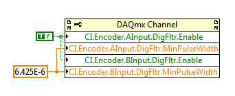
M-series cards have a digital filter integrated on the lines of the PFI (see the user manual of M series). Looks like the noise is a series of 3 ~ US of impulses (1/10 to 1/30 kHz). Of the available filtering frequencies that you can set on your M series is 6,425 US, which must ignore the impulses (high or low) that are less than 6,425 US. You can configure the digital filtering with a property node DAQmx:
One caveat is that the driver only allows you to configure the digital filtering for entries counter on M Series devices. For example, you can use a digital filtering directly on your task of encoder, but not for your sample clock HAVE. A workaround can be found here, which is to set up a dummy counter job to define the PFI filter for your task to HAVE. If you use the same PFI line for your encoder and the task to HAVE it, you should be able to just set up the PFI filter through the task of the encoder and worry for the workaround.
Regarding the RIO Flex, I think that you could implement something similar on the FPGA, but I'm probably not the best person to comment on this subject. It would be probably a lot more work to use the DAQmx API's built-in filtering.
Best regards
Maybe you are looking for
-
How can I disable voice and a black square around red symbol 'close' this window?
After a power outage, annoying voice came telling me everything I do, that is, "MSN opening, closing of window, etc..» In addition, a black square now surrounds the red circle 'close' this window. Cannot turn off the other to turn to low volume.
-
My laptop cannot find HARD drive recovery area
Hello. After that I have divided my HDD (1 TB) in 4 other partitions, I can't use the Recovery Media Creator. I have merged 4 partitions to one, as it was, but I still can't use recovery utility. The recovery partition exists, but not way to start wi
-
I disabled the menu and cannot access the drop-down list to get back them
I disabled all the menus to make a screenshot and now I can't access the drop-down list to get back them This has happened Just once or twice is today
-
My Satellite L300-110 hangs after BIOS update
My Satellite falls down after I updated the BIOS. The old version of my Satellite L300 - 110 (PSLB0E) BIOS was 1.40 and upgrade to 1.50.From there on, my system hangs over and over again. Any help please. I cannot install Office Enterprise 2007, cann
-
Satellite P750-02 t - 1080 p on a HDMI monitor
Hello I just bought a Satellite P750/02 t a few weeks previously. Buy a monitor HP 2310e yesterday and using the port HDMI is plugged. I can't get the monitor to work in 1920 x 1080, the screen displays the desktop with 1 cm all around are cropped. C