FPGA: the internal signals in ModelSim display
I have a piece of code written LabVIEW FPGA in that I am trying to simulate in ModelSim. I followed the instructions in this link, but the example is a simple incrementer with no internal signal (only the input and output).
I created a test bench and started the simulation, but the macro provided .do only adds the entries and exits to the wave window. ModelSIM lists pages and pages of processes and signals that can be added to the waveform window; all have names completely opaque. I found something called 'TheWindow', and then a subdirectory called "Thatcher" and added all these signals to the waveform window. The names are things like ResHolder00000000000001 and provide no information on where they came from.
I tried to assign labels to the sons of my LabVIEW diagram, but that did not help at all in creating useful names. I need to check the progress of States in my VI but can't find anything that seems like the appropriate signal. A lot of available under 'Thatcher' waveforms are waveforms static, uninitialized, or both. How can I assign names to internal signals so that the waveforms are actually intelligible?
On a side note, it is also a problem in the synthesizer. I'm used to using the synthesizer output to 'pre-debug"my code, but LabVIEW seems to ignore the process of inference any macro. I tried to put a SCTL with an incrementer and LabVIEW does not infer a counter. I have never seen one of my machines of State recognized in the synthesizer, even if the code works correctly.
Using ModelSim PE 10.3, I understand is not "officially supported", but the fact that the synthesizer and the Simulator have the same denomination made problem wants me eliminate this as a problem. I do not use one of the PE extensions on the version SE.
Hi Nick,
If it is not the most readable, its not too hard to find signals that you are looking for. Your biggest help will be context-sensitive help in LabVIEW. If you hover over the structures, nodes, or son, in your LabVIEW FPGA design, at the bottom of the help context window, you'll see what we call the 'name of the VHDL Instance".
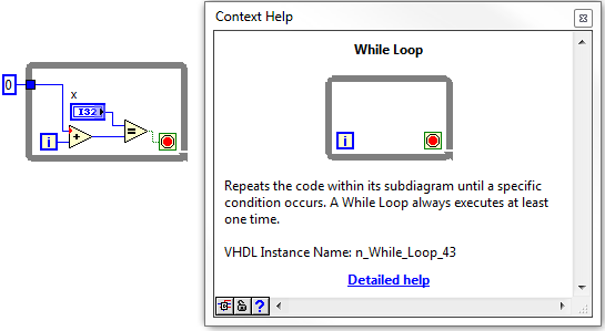
Once you navigate through the hierarchy down through the window, in the VI, you should start to see some of your top-level objects, such as while loops etc. From there, you can navigate down in whatever the level and find the wire you are looking for.
I did not have the ModelSIM on my machine, but it works for the ISIM. I wish they had a search function, so you can just type in the signal you are looking for.
Tags: NI Software
Similar Questions
-
Should I reset the FPGA FFT when changing the input signal?
Hello
I have an application based FlexRIO where I do FFT on several incoming signals. The signals will be ranked so that I get first for example 4096 samples of Ch1 and Ch2 4096 samples, etc. This means that I don't have to do it in parallel of the FFT and I would like to reuse the implementation of FFT and windowing to reduce the use of resources.
I intend using the VI Express followed by the Express VI of FFT window scaling
http://zone.NI.com/reference/en-XX/help/371599J-01/lvfpga/fpga_scaled_window/
http://zone.NI.com/reference/en-XX/help/371599J-01/lvfpga/fpga_fft/
and I'll use them inside a SCTL.
This figure comes from the section using the FFT and help illustrate the issue:
There is a discount to zero terminal for the fenestration and the FFT VI.
Are there internal registers in the windowing and FFT which force the image 1, image 2,... from the same signal or is it possible for the first entry in a framework of Ch1, the next frame belonging to Ch2, Ch3 gaze and so on and always get reliable results?
Another way to ask the same question: if I have to reset the window and FFT when changing the input signal?
Thank you
Anders
Hi Cyphish,
When using the FFT of the LabVIEW FPGA vi express and windows nationwide express vi calculations are make it point by point so there will be no problem when going through different types of measures. Therefore, you should have no problem with your application.
Best regards
Menelaos.K
-
Satellite A100-410 - no image on the internal display
Dear readers, (also strange that Toshiba sells also in the Netherlands, and I do not use the Dutch language)
I have a Toshiba Satellite A100-410
I have problems after one year only (after warranty) where to plug an external monitor.
The laptop displays not its own screen, without external screen is lighter, it starts but no picture.
I did it with Fn + F5 but nothingControlled parameters but no error detected.
It would be nice if someone could send an email with a url so that the old setting back.
It's a Windows XP MCE and the mechanic that all abducted and put Vista on.At the beginning, a lot of problems, but it was under warranty and after that install on a clean disk Vista had no problem just no image on the notebook and which isn't difficult if you use him in the hospital.
So I hope that someone can send an email with a solution.
Thank you
Seggelinck(> also strange that Toshiba sells also in the Netherlands, and I do not use the Dutch language)
Toshiba selling own products around the world... everyone here validate in the own language? Definitely bad idea...
However, your question;
Just to clarify your question; the internal screen does not work, but you can all see if you connect to the laptop to the external monitor. Is this good?Well, I doubt that this could be a software issue... maybe the internal screen is defective.
What do you thing about this idea?Usually, you should see the start screen for Toshiba at the beginning of the startup procedure. If this screen is not visible on the screen of the laptop computers, so I guess that this problem could be linked to the failure of the display.
-
LabVIEW FPGA: An internal software error in the LabVIEW FPGA Module has Unknown
Sir/Madam,
Note Labview 2012 SP1 installed about 2 weeks ago.,.
Accident occurred during the compilation of an fpga vi who worked satisfactorally in the past.
When I restarted and went to the message recomplile "LabVIEW FPGA: an internal software error in the LabVIEW FPGA Module" see attached picture of popup.
I reinstalled Labview in its entirety and backed out the changes I made to the vi but still get the same message.
Thanks in advance
Daryl
It turns out that the question was in the VI and not of LabView FPGA module as the message may indicate. I created a vacuum vi, cut and pasted items in this from the vi error and recompiled and it ran very well.
Somehow the vi has been corrupted internally.
Thank you it's fixed.
-
[FPGA] Problem with the sinusoidal signal generator
Hello!
At first I want to apologize for my English is not my mother tongue.
Hardware and software I use is:
LabVIEW 8.5
NEITHER RIO 2.4.1
NEITHER cRIO-9014 (controller in time real CompactRIO)
NEITHER cRIO-9104 (chassis and FPGA)
NEITHER 9264 (16 channels, +-10V, 16-bit voltage analogue output Module)
I made a very simple FPGA VI: a while loop, generator of sinusoidal signal and a FPGA of e/s node in the loop. I've specified the Gnerator settings by following the path:
Frequency = 50 Hz
Amplitude = 1
Phase shift = 0.00
Size of the table look-up = 1024
= 16-bit amplitude resolutionFPGA clock frequency (40 MHz)
But the wave of "sine" I got is not what I wanted to get. First of all, its amplitude is 1 V. shouldn't it be coded on 16 bits? If I wanted to get 1V I should have specified Amplitude as a 3277. In addition, 'sine' is not very detailed, it's look like "steps", as many samples vere missing. What I did wrong? I checked the samples and tutorials, I did everything the same way. A I forgot something or not has not specify other parameters?
Thanks a lot for your help!
OK, I solved a problem. It's embarrassing to admit, but maybe this will help someone else
 I blame my inexperience
The main solution to the problem was changing calibration of calibrated RAW Mode. After that, everythoing works as expected. I had a problem with a sample because I was using a multiplier to control the generated sine wave amplitude. But... She was set to 1 in the sinusoidal signal generator. That was the reason for waveform Gradin. Please, don't laugh too much

In any case, thank you for an answer! It is now resolved
-
Internal BES12 - app, the app icon is not displayed
Hello world!
We use BES12 (v.12.5.1) and a few small apps for iOS developed in-house.
Apps are built with Xcode and can be downloaded on the BES, deployed on devices, and works well, once installed on the devices.
A question we've seen on every version of BES12 we had installed in our environment is, after that the signed ipa file download UI BES12 internal process can not show the actual application icon. Its always shows an icon of the generic application on the user interface. Is the same for the 'work apps' self-service portal where the user can click on the app and start installing managed for his camera. Once the download is complete, the icon appears as expected.
Can you tell me what to do in Xcode to let the user BES12 interface (and thus self-service portal) show the correct application icon? Is it a problem in the BES12 itself?
Attached is a screenshot of the interface user of BES12 to clarify the "generic application icon.
Thanks for your support!
Kind regards
Daniel
Edit: To clarify, we use native iOS apps (no packaging for SWS or good dynamics) and Installationavecuneracine these applications on iOS actvation devices type 'MDM' only
My apologies, you are right. In BES12 there is not a way to download the icon separately for an iOS app. It is also a limitation within the application icons are not displayed on BES12 for iOS apps deployed internally.
-
PAVILION dv7-1232nr, the sound signal is displayed on the screen when changing volume disappeard.
hp pavilion dv7-1232nr, the volume signal which appears on the screen at any time the volume is set does not work as before! y at - it a point or the option which is in klicked on or off to turn off this signal!
Hello
If you have a MediaSmart software installed on your portable computer, the volume OSD (on-screen display) is provided by HP MediaSmart SmartMenu - you can download and reinstall this app from the following link.
http://ftp.HP.com/pub/SoftPaq/sp45001-45500/sp45140.exe
When the installation is complete, restart the computer and let Windows load fully before checking if it works fine now.
Kind regards
DP - K
-
First white screen of death, now black screen on the internal, external screen works
Hello
a few months before I could not suddenly start my macbook more. He had the white screen of death and absolute no functionality in addition to its departure.
A few days ago I got the macbook, open/close a couple of times so that it is operated and suddenly the keyboard LED lit and the screen
turned black. I realized that he really started and connected to the external monitor. everything works fine now in addition to the internal display.
I run Apple Hardware Test mode clamshell, but extensive testing even said that there is no material errors.
can I conclude that my screen is not faulty? I thought it of the graphics chip, but wouldn't the AHT it detects then?
Another thing to mention is that the battery should be changed (warning hint)
I tried PRAM - & resetting the SMC without success.
MacBookPro 13 "A1278 mid-2012.
I would really appreciate any kind of advice.
Thanks in advance
Alex
The symptoms you describe point to a faulty screen or display connection. Make an appointment at an Apple store genius bar for a final assessment. The event will be FREE.
Ciao.
-
WNR2000v4 continues to change the internal ip address
Hello
For some time, I have a strange problem with my WNR2000v4. time to time the Exchange Router ip address internal of himself. The standard/default ip address is 192.168.1.1, but for some reason any change the router to 10.0.0.1. According to the notice, it is because of problems with my internet provider. If this happens, I have to manually change again to the correct internal ip address.
My setup is very simple, the internet signal is coming in my house received by my modem (ubee) and then it is given to the netgear WNR2000v4 model. I do not know the ip address of the modem or how it works, but my external ip address is in the 94.*. *. * range. So it seems to me that there must be no problem at all.
Kind regards
Anonymous
Hi Andy,.
I have some additional information on this topic from my ISP community. This is a rough translation with google translate, I hope you understand.
This apparently "strange phenomenon" can be explained. What I can say at this stage, is that the two parties have no guilt here. This is due to two requirements that a manufacturer must meet when NAT is used with the product. See https://tools.ietf.org/html/rfc4787#section-4.4 for more details.
Why you can see that a reset of the modem, it is because the modem RF interface is not yet connected to the CMTS. Therefore, the DHCP server on the modem itself is active until there is a link with the CMTS. The router WAN interface detects a link down / event and then again try to obtain an IP address. Router WAN interface will then receive a private at this time, IP from the modem of the same sequence, which is then used in your router. The modem doesn't know that your router uses internally the same private IP range. Clearly, this is a problem and set up your router correctly responds by himself with another range of IP private. Why the DHCP server on the modem is active when there is no connection with the CMTS? Because you still can connect to the management interface of the modem.
Manufacturer must implement one of the following two things to make it work.
All traffic between internal / exterene correct translation and transfer customers. It is difficult because you need a solution like Session Traversal utilities for NAT server. If two clients are the same ISP that makes double NAT, you also depend on the correct application of crossed NAT of the ISP router.
The second solution is automatically ensure that the internal and external IP address ranges do not overlap / are identical.
Manufacturers a logically opted for the second solution easy. How can you solve this problem permanently? If your local network for example. 192.168.0.0 network class C can be used for example. Set your router to use IP network 192.168.1.0.
-
Equium A300D - power of the weak signal on built in wireless
I've had my Toshiba Equium A300D - 13 X for a few years now. I also have sky ADSL broadband for a few years. My signal from the router (netgear) until a couple of months has been very well. The router is located in my hall, and I use my laptop mostly in the lounge which is through a wall, 3 or 4 meters. Strength showing on the wireless icon in the tool bar used at least 4 or 5 bars but now the best I have is 3 bars force and my connection is variable with Web pages take longer to load.
If anyone has experienced this? Could there be something wrong with the internal wireless antenna?
Any advice would be great.
Hello
Have you changed anything on your phone (settings, updates), router (update firmware, settings), or perhaps in the region (placed a device which can interfere with the signal)?
-
problem with the intern memory full
I do bike G4 haveba + with a Samsung Fast 64 GB micro sd and formatted as intern memory.
Onnthat cart is 54 GB of free, but intern memory of the bike is almost full and problems.
IMDO have Osmand and amd downloaded Google maps both use a large part of intern space. I tried to move those applications to the sd cart and he wants to go. What can I do to move people or other apps to sd cart?
Not all applications can be moved to the internal memory. You can not change this. But you can move everything else, if you do not have.
If you select your SD card and it only displays the applications and data being cached, then nothing has been migrated to it. Click the menu 3 dot and select migrate data
-
Acquisition with USRP 2953R of the GPS signal
Hi all
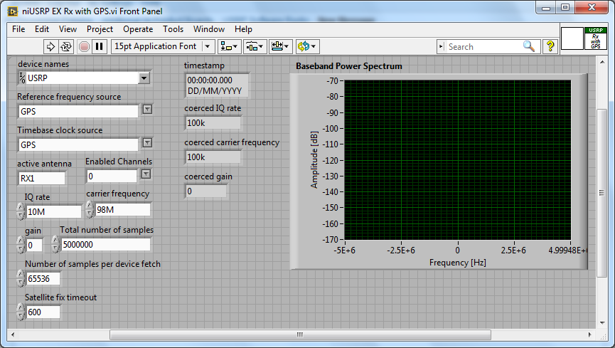
How can I configure a 2953R USRP receive GPS signals? I have an antenna VERT900 connected to the GPS ANT of the USRP port, but in the example VI 'niUSRP EX Rx with GPS', I can't reference this port in the field 'Active antenna'. I put only things like TX/RX or RX1 etc. Should what values I put in other areas as well? I know that the L1 band is 1575,42 MHz.
Hello
The example you posted shows you how to acquire an RF signal on the ports of the USRP with internal clock RF and sources of reference defined in the GPS.
To make it work properly, you must have a GPS antenna connected to the Terminal on the GPS device and installed in a place that receives a good level of GPS signal.
The other control of antenna on the schema defines the port on which to receive the RF signal.
If you want to capture and analyze the signal GPS (RF) itself, you can tune into the front-end RF (carrier frequency) at the right frequency of GPS band and connect your GPS antenna to the RF port.
You can use the simple niUSRP EX Rx continuous Async.vi in this case (but may not work due to the very low consumption of GPS RF signal)
-
MyRIO FPGA read framework signals SENT
Hello community,
I now have a myRIO with Labview 2013. I try to read a digital signal to a sensor on the port DIO0 (C-Port). It works very well. The problem is that I don't know how to find the start (the SYNC nibble) of the frame SENT - and how it works with the ticks of the clock / time clock of the FPGA (40 Mhz) system. I do not understand the meaning of the clock. ticks of the clock.
The next problem is to measure the time between a front down to falling edge. In fact I can detect every falling edge of the signal SENT but I cannot measure the actual time between them. How can I measure the real time based on the system FPGA clock time? The nibble of SYNCHRONIZATION were all 56 time graduations. But how long are 56 ticks?
Best regards
Basti
Hello, Alexander.
Thank you. It works very well.
Now my problems are solved. The main problem was to build something that is capable of converting 56 ticks of the SYNC signal SENT for correct ticks of the sampled signal. The two frequencies, the Signal SENT (333kHz) and the sampled signal (40 Mhz) are different, so I divided the frequency of the signal sampled frequency of the Signal SENT - (factor of about 120). Now I can convert 56 ticks to correct the number of ticks of the sampled signal and I can find the SYNC - Puls in FEEL. The result of 56 times the factor of 120 ticks is 6720 ticks. So, I convert ticks to the correct frequency.
Thank you very much for your help!
Best regards
Sebastian
-
Is it possible to use the internal clock for meter tasks in the buffer?
Hello
Hardware: USB term mass 6251
Software: LabView 2011 SP1
I need to measure the angular lever position and speed of a carpet. For that I use two quadrature encoders. To accurately calculate the speed I use buffered from the measures of position using one of the available onboard counters. I understand that for this technique, I provide a sample for the meter clock. I wonder if it is possible to use the internal time base. Note that both of my counters are used so I can't generate a signal to clock with them.
I found two conflicting pages related to my problem:
1) http://digital.ni.com/public.nsf/allkb/EA7FFFEAFC3E1D85862572F700699530
2) http://digital.ni.com/public.nsf/allkb/775290A3121D1FFC862577140074D3B3
The first says that I can use the internal clock of 100 kHz, and the other says that I have an external clock.
Comments/solutions?
Javad
Hi Javad,
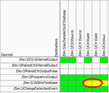
On your specific device, there is not a direct route from the time base of 100 kHz for the meter (according to the routing table of MAX):
Yellow cell indicates that a route is possible but there is not direct (the "gate" terminal is used as sample clock for counters of the M series). Mouse on the cell reveals yellow that make this route really requires the use of a counter (so it is not suitable for your application).
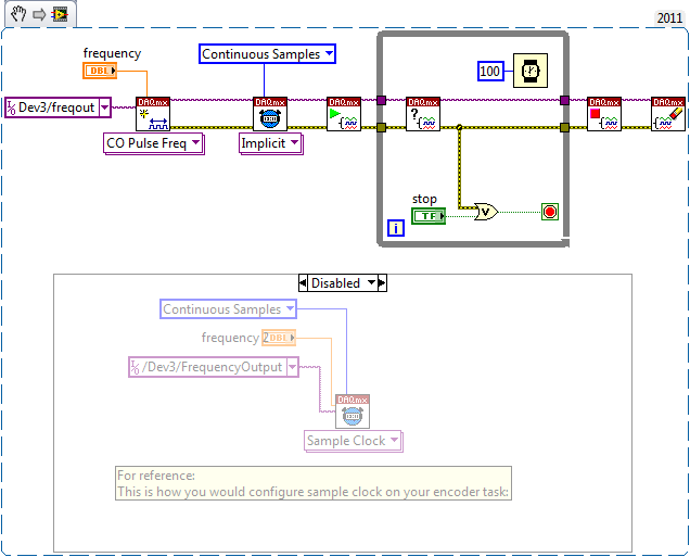
On the line above "100kHzTimebase" you will notice it is called 'FrequencyOutput', which does not have a direct route to the door. This would be the way to go if you want to route 100 kHz (or some other frequency) as your sample counter clock - you can set it up the same way to a standard meter output task:
The output frequency doesn't have that many features like a meter output, but it is able to generate a continuous stable frequency. There are only 32 different frequencies that can be generated using Freq Out on the 6251:
{10 MHz, 100 kHz} / {01:16}
Do not forget that the resolution of your measure of frequency by using this method will be equal to how many times you update the measure (hopefully, that makes sense). In other words, if at the end of all the 1 second, you take the total number of charges since the last second, you would have a 1 per second equal resolution change in the number. If you take the difference twice per second, you would end up with half the resolution. You will be sampling the account register fairly quickly, but you will need only to do the calculation of the frequency after that all N samples in order to obtain a significant number.
Another method that will certainly give a higher resolution in less time at typical speeds of coders is to set up a measurement of the frequency (the counter will count the internal 80 MHz base time period your external signal and the pilot calculates the frequency based on the result). This method uses only a single entry - so you can just feed the 'A' your encoder quadrature signal (the method will not work if you are interested in absolute position or direction). Without using signals A and B together, you will be susceptible to noise (which is common to have a quadrature encoder) that you want to delete (perhaps by setting up a digital filter). Finally, you want to set a reasonable timeout on your reader calls (which will be blocked until a period of your external signal occurs), and the error-200284 handle simply report "0Hz" to make sure that your program is still sensitive even without an external signal present.
Best regards
-
To access the internal settings of a block
Hi all
I use the LabVIEW FPGA 2015 for a project. I would like to access the internal got (data type, size, etc.) as the window scaling, FFT, blocks
or another block. Or even change the size of an external FIFO without having to open the game menu. Is this possible in LabVIEW?
Thanks in advance,
Hazem
You can right click... 'convert Subvi' to open the diagram and repeat for the inner screws.
This allows you to see the actual code. You may be able to recover fragments of code and use your own code.
Maybe you are looking for
-
Strange shadows on the Sierra of the Mac OS on an external monitor
After upgrading to Mac OS Sierra, I noticed that there are these strange shadows. It of almost like the gradient of a shadow is not fluid and smooth: Screenshots: https://www.dropbox.com/s/dj6g3x68c9ggwez/screenshot%202016-09-24%2008.34.42.PNG? DL =
-
connect computer to TV with cable
I want to connect my HP p6560sc computer to a TV. When I plug this cable into the computer? Grateful for the help
-
HPE h8-1036de: update of the graphics card (an ASUS / NVIdia GTX750Ti in a desktop HP HPE h8-1036de)
Hello world! Thank you for reading this post and help me. I am trying to build a new graphics card (an ASUS / NVIdia GTX750Ti) in a desktop HP (HPE h8-1036de) PC. The PC beeps at startup. I guess that the card is powered (note that this is the 4 GB c
-
Impossible to sync my Ipod to computer
original title: my Ipod synchronization I had to wipe computer and everything may start again. My Ipod was syncd to the computer before, but doesn't seem to be present. How can I get to sync again?
-
I select envelopes DL size MSWord 'Direct mail' (& central position in the tape) and I load envelopes DL size cassette printer in a central position. But when I hit print, I get a paper mismatch error.