read the analog signal 0-10 volts of NI6123
I'm reading the analog signal of NI 6123. The range of the analog signal is 0 to 10 volts. This works well when the signal voltage is 0 to 5v (0 ~ 32767). But when the signal is 5 to 10 volts, the value read is always 32767. I also tried the different reading function: DAQmxReadBinaryI32, DAQmxReadBinaryU16, DAQmxReadBinaryU32. The value is identical to DAQmxReadBinaryI16. My OS is windows vista. Here's the part of my codes.
**************************************************************************************************************************************************************************
Create analog data tasks.
DAQmxErrChk (DAQmxCreateTask("",&datHandler));
DAQmxErrChk (DAQmxCreateAIVoltageChan(datHandler,"Dev1/ai0:7","",DAQmx_Val_Cfg_Default,-10,10,DAQmx_Val_Volts,NULL));)
DAQmxErrChk (DAQmxCfgSampClkTiming(datHandler,"",RATE,DAQmx_Val_Rising,DAQmx_Val_ContSamps,RATE*MAXLAS));
DAQmxErrChk (GetTerminalNameWithDevPrefix(datHandler,"ai/SampleClock",trigName));
Create counter tasks.
DAQmxErrChk (DAQmxCreateTask("",&ctrHandler));
DAQmxErrChk (DAQmxCreateCICountEdgesChan(ctrHandler,"Dev1/ctr1","",DAQmx_Val_Rising,0,DAQmx_Val_ExtControlled));
DAQmxErrChk (DAQmxCfgSampClkTiming(ctrHandler,trigName,RATE,DAQmx_Val_Rising,DAQmx_Val_ContSamps,RATE));
DAQmxErrChk (DAQmxRegisterEveryNSamplesEvent (datHandler, DAQmx_Val_Acquired_Into_Buffer, SPLEEN, 0, EveryNCallback, NULL));
DAQmxErrChk (DAQmxRegisterDoneEvent(datHandler,0,DoneCallback,));
Start the task.
DAQmxErrChk (DAQmxStartTask (ctrHandler));
DAQmxErrChk (DAQmxStartTask (datHandler));
In the call back function:
DAQmxErrChk (DAQmxReadBinaryI16 (datHandler, SPLEEN, 3.0, DAQmx_Val_GroupByChannel, data.laser, MISS * MAXLAS, & (data.dataRead), NULL));
DAQmxErrChk (DAQmxReadCounterU32 (ctrHandler, SPLEEN, 3.0, data.counter, SPLEEN, & (data.ctrRead), NULL));
write data to the file.
data.cfile.Write (data.counter, sizeof (int32) * RATE);
data.cfile.Write (data.laser, sizeof (int16) * RATE * MAXLAS);
**************************************************************************************************************************************************************************
Thanks in advance
To make sure that your device is working properly, I recommend first to test the entry in measurement and Automation Explorer (MAX) analog. You can test your device by right clicking on it in the configuration tree and selecting test panels. See if you acquired signal 0 - 10V as you expect. The next step would be to try one of the sample programs that perform a task of analog input. These examples can be found in the start menu > programs > National Instruments > NOR-DAQ > text based code supported. Try an example that does an analog input continues and double bed (instead of binary data not adjusted).
Your program looks good at first so I found nothing that stood out. However, one thing to check is if your function generator (or signal source) expects a 50 ohm or high impedance. This could cause reflections of the signal and cause the device to possibly read a voltage of half of the desired value.
Tags: NI Hardware
Similar Questions
-
Reading of analog signal using DAQPad-6016
I'm reading an analog signal using DAQPad-6016. An entry is on the ground, the other is Vdc. I can't operate at MAX and I'm confused becaue MAX alone gives me an option for differential reading, but the list of pins give enough information on how to connect in a different way. Is there a reference as well?
Hello, Bernadette.
This link should have what it takes to equip themselves properly: http://www.ni.com/gettingstarted/setuphardware/dataacquisition/analogvoltage.htm
After that you have put work in place, specifically see step 11 for check the connections of the device.
I hope this helps!
-
How to read the analog inputs of one Board of R for (PXI-7851R) series
You can guide me please with the steps for reading of the analog inputs of a series a. card I use as the target fpga PXI-7851R.
Have you looked at the examples provided with LabVIEW? There are examples showing how to read the analog inputs.
-
Problem in reading the PWM signals in myRIO 1900
Hi guys,.
I work with myRIO to generate PWM pulses.
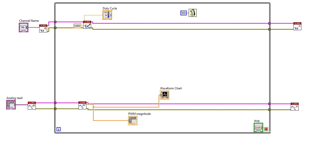
Here is the block diagram of my circuit.
I connected external to the analog input pin PWM pin. So I can watch the PWM pulse in the waveform table.
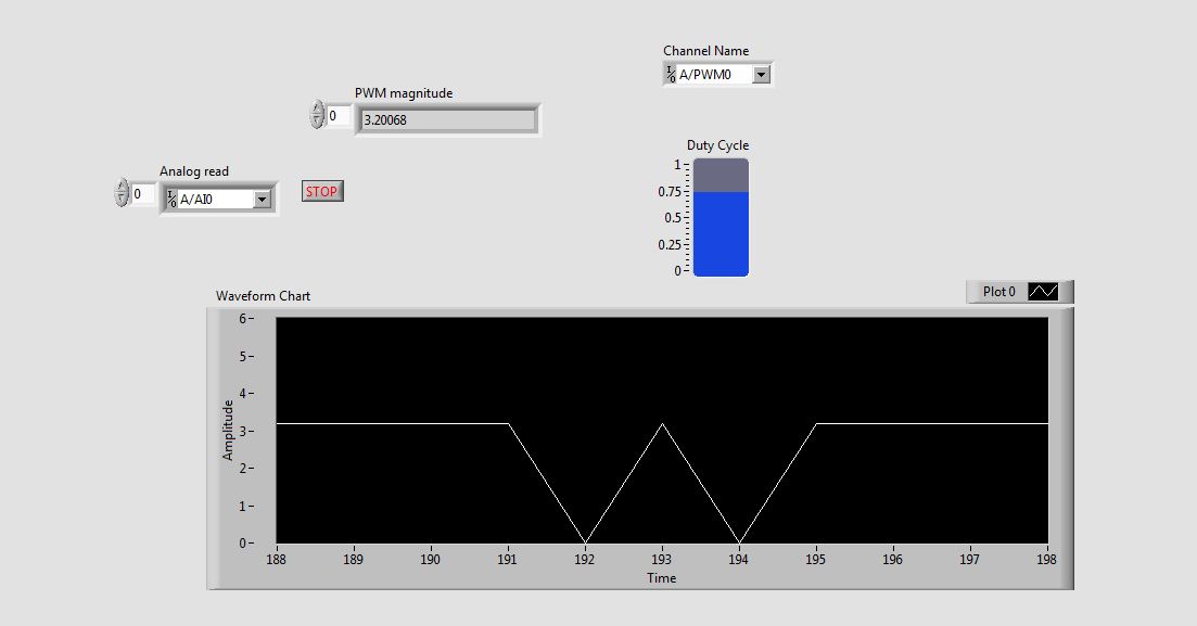
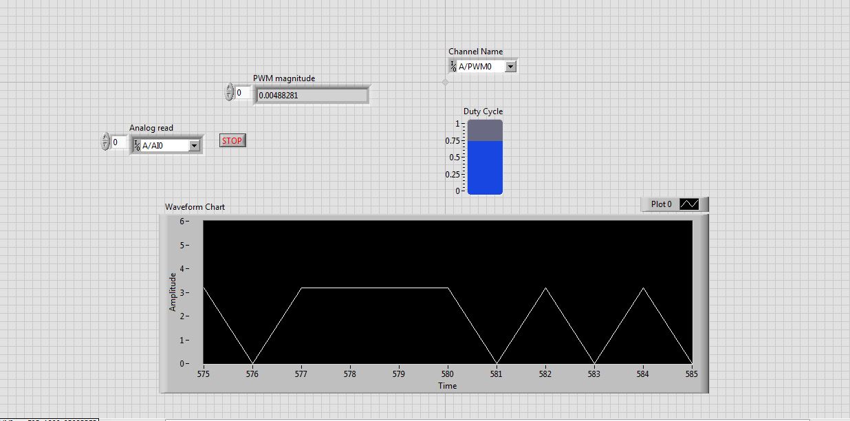
But the waveform is not clear. This is as shown in the screenshot.
See that the waveform is not correct. When I'm watching the same PWM pulses in the CRO (cathode ray Oscilloscope, oscilloscope real in the real world), I get exactly the waveform. that is, the PWM pulses are generated correctly. But the analog read is unable to read the PWM pulses.
I faced the same problem with the pin of analog reading earlier when I read the input voltage. Is not give continuous reading of the voltage input.
Please guide me how to read these impulses via analog read.
Please tell me at what frequency range, I can use this myRIO to generate impulses?
I am able to use 40 kHz?
Hi rcs.
The desired pulse frequency is 10 KHz. My sampling rate must therefore 100 kHz, which is not possible in data acquisition mode. There is another problem with the myRIO. Only AI0, BI0 and CI0 has n-sample mode. The analog input pins is still have no n-sample mode. But in my project, I need 4 pins of I in n-sample mode, which is not possible. In addition, the sampling rate should also be favourable, which does not happen in my case. We can say that this is a disadvantage of myRIO with data acquisition mode.
The only alternative to solve this problem is to use FPGA in myRIO.
He can taste a 25nS rate.
But little complexity is there -
myDAQ inaccurate reading of the analog signal
Hello
I'm usign the myDAQ in lieu of a USB6341 who is busy on another configuration. The DIF is with the USB6341 I connect two analog inputs without any noise problems, whereas with the myDAQ, I get what you see in the image as an attachment.
Now, (the white line) of a flat line but often I get all these ouliers tips coming clearly through the myDAQ.
Two different voltage on two analog input signals of the my DAQ I can see the same spikes descending in the same moments for both signals, which is another confirmation that the noise is added by the myDAQ.
Also, try different myDAQs (we have many University) does not solve the problem.
Any idea on how to solve this problem?
Thank you very much.
Giacomo
Hello, Giacomo,.
Sorry for the late reply.
Now that you mention the myDAQ DMM.
Please note that the DMM uses a different circuit (Figure 2, page 5):
http://www.NI.com/PDF/manuals/373060e.PDFHow the signal looks like with the myDAQ scope Soft Front Panel?
Although the USB-6341 has different (and better) specifications seems to be rather a noise or signal problem floating.
Can you 100% certainly confirm that you do not see this problem with the USB-6341 when you perform a differential measure?Have you tried the method explained in Figure 7 on page 13?
Do you see a difference when doing this? -
Hey,.
Is it possible to read a signal HERE, with a range of 1 mV-150 mV, thanks to an acquisition of data USB-6210?
How do we?
Kind regards
Filip Van Boxstael
-200 mV to + 200mV is a range. The DAQ hardware will measure a voltage within this range. If you need to measure something outside this range, you must select the next higher range. Since you mention 150mV for you the maximum voltage, 200mV beach is perfect.
-
I just installed a diamond ATI TV Wonder HD 750 PCIe on my 64 bit Windows 7 system (it's actually the second tuner card I tried) and still get the same problem. Media Center recognizes the card and both tuners analog and digital, but fails the analogue listening. I get digital very well. I tried to add a channel manually and still no luck. I use cable TV with no cable box and tested the signal on my TV and receive all channels.
I also downloaded the latest Diamond driver and installed all updates more recent windows.
In Media Center, I tried to automaticlly and manually select my signal and each combination, but available with no luck.
Can you please help
Rob
Out of curiosity, what was the 'other tuner"which has been tried before?
Honestly, my recommendation would be to return the tuner (if possible) and get a combo tuner or hybrid that is known to work properly. My first recommendation would be for a Hauppauge HVR-2250 (Council dual combo/hybrid), because it works wonderfully in MC as a tuner NTSC/Clear-QAM of combo/hybrid. MC knows how to treat as what it is, and it works very, very well (I have not one.)
That, or an AverTV Combo G2 (which is not as flexible as the ' 2250, where its slightly lower price.)
HTH,
ChrisMS - MVP (Media Center) [If this post can help solve your problem, please click the 'Mark as answer' or 'Useful' at the top of this message.] [Marking a post as answer, or relatively useful, you help others find the answer more quickly.]
-
generation of digital, analog signals read snap SMU-6358
I have two SMU-6358 card and I want to send control signals to my camera and read the analog signals from the device with them.
For the digital control signals, I tried to set up a system where I specify the identifiers of the pins, bring them into arrays of strings - the respective waveforms would be collected in the tables too - and I transfer them to a VI of inputs/outputs multiples that puts digital waveforms for the cards output pins.
I developed this code here, but it doesn't seem to work. I can't understand how I can convert the string and form table wave to meet the requirements of the input/output VI or which another VI I could use to do the job. Or is there a smarter way to do it?
Thank you
Kriváň
Dear Kriváň
Please find attached the VI in LV 8.6 format. Also, I HIGHLY recommend to rearrange the front panel and which makes it neater, your code is very hard to read and not structured at all. I hope this helps!
-
How do I get the analog input signal and send it to output analog (real time)
Hello world
I do a simple task in Visual C++ and I use PCI-6221(37 pin).
Basically, I want to send the same signal of "analog input" to the "analog output".
at the same time (or almost), to make real-time application.
Can someone provide me with sample program please.
I would be grateful if you could provide me with the great tutorial that explains
step by step everything about NOR-DAQmx for C/C++ programming.
Best regards
Khassan
This is my code in C++, you can optimize it if that seems too messy. This code reads the analog input signals and exports it through the analog outputs.
To make this code additional work of the directories include and library directories must be added to OR.
I hope it helps someone.
#include
#include
#include "NIDAQmx.h".
#include#define DAQmxErrChk (functionCall) {if (DAQmxFailed (error = (functionCall))) {goto error ;}}
int main (int argc, char * argv [])
{
Int32 error = 0;
TaskHandle taskHandleRead = 0, taskHandleWrite = 0;
Read Int32 = 0;
float64 context [1000];
char errBuffRead [2048] = {'\0'};
char errBuffWrite [2048] = {'\0'};
bool32 done = 0;
Int32 wrote;DAQmxErrChk (DAQmxCreateTask("",&taskHandleRead));
DAQmxErrChk (DAQmxCreateAIVoltageChan(taskHandleRead,"Dev1/ai0","",DAQmx_Val_Cfg_Default,-10.0,10.0,DAQmx_Val_Volts,NULL));
DAQmxErrChk (DAQmxCfgSampClkTiming(taskHandleRead,"",100.0,DAQmx_Val_Rising,DAQmx_Val_ContSamps,0));
DAQmxErrChk (DAQmxCreateTask("",&taskHandleWrite));
DAQmxErrChk (DAQmxCreateAOVoltageChan(taskHandleWrite,"Dev1/ao0","",-10.0,10.0,DAQmx_Val_Volts,NULL));
DAQmxErrChk (DAQmxCfgSampClkTiming(taskHandleWrite,"ai/SampleClock",100.0,DAQmx_Val_Rising,DAQmx_Val_ContSamps,1000));DAQmxErrChk (DAQmxStartTask (taskHandleRead));
DAQmxErrChk (DAQmxStartTask (taskHandleWrite));While (! fact &! _kbhit())
{
DAQmxErrChk (DAQmxReadAnalogF64(taskHandleRead,1,10,DAQmx_Val_GroupByScanNumber,dataRead,1000,&read,));
DAQmxErrChk (DAQmxWriteAnalogF64(taskHandleWrite,read,0,10.0,DAQmx_Val_GroupByChannel,dataRead,&written,));
}
_getch();Error:
If (DAQmxFailed (error)){
DAQmxGetExtendedErrorInfo (errBuffRead, 2048);
DAQmxGetExtendedErrorInfo (errBuffWrite, 2048);
}
If (taskHandleRead! = 0){
DAQmxStopTask (taskHandleRead);
DAQmxClearTask (taskHandleRead);
}
If (taskHandleWrite! = 0){
DAQmxStopTask (taskHandleWrite);
DAQmxClearTask (taskHandleWrite);
}
If {(DAQmxFailed (error))
printf ("error DAQmx: %s\n",errBuffRead); ")
printf ("error DAQmx: %s\n",errBuffWrite); ")
}
printf ("end of the program, press the Enter key to quit\n");
GetChar ();
return 0;
} -
Generation of the trigger (or TTL) analog signal
Hello world
Well I look at the droplet, riding on the vibrating bath. In this case I have to synchronize the device with the accelerometers.
Accelerometers are connected to the vibrating plate vibrating sinusoidal with frequency of 80 Hz. I am the acquisition of acceleration using NOR-DAQ USB 6212. A camera (Camera Link Basler, NI PCIe-1433) is used to acquire images of the vibrating plate. The frame rate of the camera is 20 Hz which controlled by external signal (TTL) or camera attributes.
I would like to generate a trigger of data acquisition (signal HAVE) to the camera at the first minimum acceleration in the attachment. I've also attached the file vi. Could if it you please let me know if is there anyway we can generate the trigger of the analog signal.
See you soon
NGO
Hello, NGO,
Can you post the update VI?
-
Good day to all,
I use NEITHER-7350, LAbview 8.5 and try to measure the voltage from a power source.
Is there a screw that read the analog inputs. I can't open the examples.
Thank you
Have you watched the DAQmx? Create a virtual channel, start the task and read the value.
http://zone.NI.com/DevZone/CDA/tut/p/ID/5370
-
How to read 3 analog inputs simultaneously with 6070E?
Hello
I wanted to read 3 analog signals simultaneously using cards of acquiring data NI PXI-6070E and Labview 2010.
I can with success read and record the 1 signal (which you can see in the attachment), but do not know and can not find examples on how to read 3 signals simultaneously. Any help, especially a simple example would be great.
Thank you!
Just click on = pull down from the constant physical channel, select Browse and shift-click or Ctl-click here to add other channels. You can also type in new channels with the ai0 syntax: 2 for three continuous channels for example.
-
How can I use my PXI-6115 meter analog signal trigger to generate pulses of frequency
I work on a PXI-6115 DAQ card and want to using the analog signal to trigger the counter it's generating frequency pulses. The manual says the analog trigger is supported, but I can't use an analog signal to trigger the start of work, in the test, I use the counter 0 to generate pulses and use the signal input port analog trigger PFI 0, can someone tell me what it is? My test VI. & error message appears in the attachment.
Best regards
If you read the error you can see digital triggers are the available trigger only when you use the output of the counter.
You can work around this by setting up a dummy analog input task which will trigger an internal digital triggering when he sees the right analog trigger.
See this thread for more details:
-
How to write constantly to analog output and read from analog inputs
Hi all -
I had a question about writing continuously to analog output reading simultaneously an analog input.
It's my first time to post a message to the community, so please let me know if I made mistakes.
I use Labview 2011 with a NEITHER-DAQ USB 6215.
I'm looking to generate a waveform and write it continuously in an analog output. It is then connected to an entry on the acquisition of data, where I am trying to sample the analog signal. (I realize, there is a system of trivial, but I'm hoping to build on it once I have run).
The task of reading from the analog input works fine, as I tested it in several other cases. I have a problem writing to the analog output.
For this task, I tried to follow the "Gen Cont Wfm Clck Int' VI to generate the wave form and start the task. I then try to write to the output of the analog timed loop. However, it does not seem to transmit a signal and doesn't give me any errors.
I have attached the VI but also a screenshot.
Please let me know if anyone has any ideas. I would really appreciate the help!
Thank you
Peter Borgstrom
We will review your tasks one at a time. First of all, the task of generation/Analog output Waveform. Generate you a waveform (I'm unsure of your VI if it is a fixed waveform or not) and send it to a defined output function to produce a waveform continuously, using N-channel and samples of N (where you set not these previously). You should not put this inside has timed loop, as the DAQ hardware has its own clock - if you simply put it in a while loop (with a stop to break out of the loop), the loop will call the function for the first points of N, wait until all N have been taken out, then call it again to another N points (up to what you press Stop).
Now, suppose that you have the output connected to a load voltage (say a decent resistance). You can wire the input terminals of your A/D converter through the same load and set up a similar analog input loop, running in parallel (i.e. in its own independent of the OD loop, while loop). You pourriez start together (with, say, a merged error since the initialization code line loops HAVE and AO become lines of error in "loops of sampling" described above), but you might want to delay loop (a little) the AI so that the OD has a chance to set the voltage before the bed.
I hope this helps.
BS
-
NEITHER 6052e: can I re - route the analog output of DAQ for PFI?
Hello
Does anyone know if it is possible to route analog output to one of the PFI (e.g. PFI0)? I use NEITHER 6052e and I would do the following: 1) output a signal to DAQ0; 2) then a few hundred milliseconds a signal of DAQ1; and then 3) read out a simple analog pulse on any output connector external to trigger an external device.
Thank you very much for your help!
Hello sometimes.
Could you please provide more information about your hardware configuration:
What devices are DAQ0 and DAQ1?
Are you using a PXI and PCI 6052?
When you say AO reroute to PFI do you mean you're trying to wire AO into a PFI line for release purposes or are you trying to exit and the analog signal of a PFI line?
Maybe you are looking for
-
The page does not match the screen and the fonts are too small. I can't change settings
I can't get any page to fit entirely on the screen. I also can't seem to change the font that is too small. I tried to make changes in the section options, but nothing happens.
-
Satellite A200 - 1 GB: Questions on downgrade from Vista to XP
Hello. I have a Toshiba Satellite A200 - 1 GB and I want to downgrade to XP, but I have a few questions. + I install XP using nlite. + 1. I have 2 partitions and I would like to know if my other partition (not the one with the operating system) will
-
Amount incorrect RAM shown on properties
Hello My laptop has 2 RAM slots, each with 512 MB of RAM inserted. However, properties on my computer only shows that I have 896 MB, although I did 1 GB. Why is this? PS my laptop is a Compaq Presario V5000 with XP Home SP3. Thank you.
-
How to install Word Art in Vista?
How do we install the word art in Vista?
-
RALink driver bluetooth pcie is missing in windows 8.1
bluetooth does not work after update of windows 8 to 8.1, and the ralink pcie driver bluetooth display is missing. Help, please