data plc labview
First of all thank you for anyone who reads this, I am very new to LabVIEW and I think it is perhaps a matter of trival, but I'm not sure.
I am building a test bed to measure the angle of vs couple of clutch disc to find the hystersis. I am confedient that my program is very well to save the data. I am usin a servomotor to apply the couple and when the couple gets to high I want to the plc to turn off the servo motor. I want to LabVIEW for data acquisition, but the plc for the control. I have no experience with modbus. I was wondering if I could share the output by the couple with the plc and LabVIEW transducer or would it weaken my signal and affect my data? The torque converter is a mv/v output, the tourque transducer is TRS - 20K of transducer techniques. I'll use a PLC direct automation and a NOR-9237.
http://www.transducertechniques.com/TRS-torque-sensor.aspx
Thanks for your time
Hi all
I thank very you much for helping out Carl.
Carl,
If you are looking for the cheapest and most reliable solution, I think Dave has a great solution. However, this library is not directly supported by OR so I will be unable to help.
Whatever solution you choose, I recommend always scrutinize watchdog timers.
http://en.Wikipedia.org/wiki/Watchdog_timer
It is a good method to give up your PLC, if the computer breaks down.
Kind regards
Tags: NI Software
Similar Questions
-
I want to send data using labVIEW to arduino using write visa and the process and to take action using arduino. After that, I want to arduino to send out necessary via a serial port to labVIEW which should be read using visa read and store in a chain. While I am able to write or read both individually, I can't do it consecutively. I used advanced read and write vi for checking my code, but nothing is helping. The wrong bed 'time delay before execution. " Please let me know where I can go wrong. Also is it possible to write code for hx711 using labVIEW
1. you need not "\n" on your orders println(). This command adds an end of line character already in the message.
2. you get the error because you have a loop around your reading. After the first reading (well technically, the second because of you add an extra line end character), there is nothing left in the port. As a result, you will get the timeout.
3. you should really consider using a Structure of the event. This way you just don't write and read when you press the Write button and you can also use the structure of the event to make the loop to stop. I also go up to close the port inside the stop-> value Change event.

-
reading data in labview to accdb file
Hello.
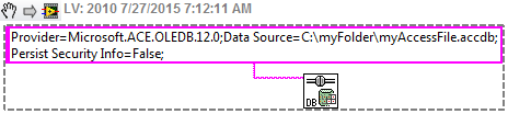
All I want to do is to read the data into a file (MS Access 2007 and later) .accdb and be able to use these data in labview. It's just a table with a group of numbers. I know how with excel but I'm getting confused with MS acess. I'm trying to play with LabSQL right now but still get confused.
Help, please!
Thank you.
What are you specifically confused about? Before using LabSQL, I suggest that you find a good tutorial on the SQL language. Database Toolbox of OR can also be used. It hides some of the complexity of the SQL for beginners.
-
import excel data to labVIEW, filtering and exporting to Excel
LabVIEW dear specialists,
I have about 2500 data each for acceleration and force stored in two excel columns of the worksheet as well as time data in another column. My problem is to purify my data of noise so I could generate thin sinusoidal signals for my thesis. I'm still new to labVIEW and I would like to ask for help to import my data from labVIEW, filter and exporting to Excel. Please help me. I enclose my data below. Thank you very much.
froebaruch
Hello!
These could be good starting points:
http://www.NI.com/analysis/Excel.htm
https://decibel.NI.com/content/docs/doc-8226
A few examples delivered with Labview, too.
Kind regards
Marco
-
Dashboard of data for LabVIEW with ad-hoc wifi?
Hello
We have a laptop and we run a LabView control and acquisition of data on this subject program. We would like to have access to some of the values of the "indicators through an android tablet, so during an operation manual tap on our facilities, we could see remotely what happens with some measured values in our application LabView.
The ethernet port is not available on this laptop, it is used for a sensor. It has wifi and bluetooth adapter. What would be the easiest solution to access the LabView app on this laptop from the Android device by using the "dashboard of data for LabView" android app? For security reasons, this laptop can't access internet, but of course, we could all just put a near wireless router (and not connect to the internet), and the laptop computer and the android Tablet access the same wifi network. I guess it should work, Yes?
Or is it possible to make a connection to wifi ad-hoc between the laptop and the Tablet and use the DataDashboard? Anyone has any experience with such a solution?
Last question: or what a Bluetooth connection? Might work?
Thanks a lot for the tips!
Kind regards
Hi man,
I recommend you connect your tablet as you described.
_________| | ---> Network---> sensor cable
| DAQ App |
| Windows | ---> WiFi---> gateway---> Tablet
| |
---------------
I don't think that it is possible to use the Bluetooth with the application of the dashboard of data for Android. I can't find any information on Bluetooth, only for the WiFi.
Best regards, Stephan
-
How to select the path of data through labview
Hello gurus...
I'm new user in labview. I want to read and write to the database via labivew. I have
read and write the program. Now, I want to choose the way of storage of data through labview.
I tried different ways, but I couldn't.
First of all read and write the program I did via the UDL file path. Now, I want to choose ".mdb" file path directly.I do not know how...
So if you know please help me...
ThanksConcerning
Joel M
IndiaRather than trying to create an Access database, I have simply included a blank database with the installation. Open, build the tables as required (as your example shows), and then copy (using the copy of the palette of Advanced File i/o) whenever you need it. Your program will need to know where it is, therefore, store the connection information in a configuration file (as already mentioned) is a possibility.
Here's how to use a connection string to open a database:
-
Data for LabView - Motorolla RAZR dashboard
When view LabView, the Android Market data dashboard tells me, 'your device is not compatible with this item."
I have a Motorola RAZR. Any suggestions?
Hello duane,.
At that time, dashboard of data for LabVIEW is available on shelves. In addition to the Apple iPad and iPad 2, Android tablets only under 2.3 or later are supported. To support the Tablet 7 '' Android, we had to make some design changes. It should be even more changes due to the small size of a phone. We might consider a version for phones based on the popularity of the application on each platform and the information received in return. For more information, see the product page or the LabVIEW Web Interface Builder and data dashboard discussion forum.
Grant M.
Senior Software Engineer | LabVIEW tablets | National Instruments -
How to read the Serial Arduino data using labview VISA?
Hi =). Im a beginner work reading data series from an arduino but im facing... Lets do it step by step
I built a voltage divider circuit which gives from output
from 0 to 5V. The output of this circuit is sent to a 0 analog input pin
of a Committee of Arduino Duemilanove.(1) Firstly, I connected the cable to connect to my laptop USB the Arduino.
(2) I went to start-> control
Control Panel-> system-> hardware-> Device Manager. Check the Ports (COM
& LPT). In my laptop I can see USB Serial Port (COM4). Now I know only in
LabVIEW that I must read the data series COM 4.(3) to the side of the arduino, here's the code to read changes in voltage
entered to analog pin 0. The last line of 'delay' determines the sampling
Rate of how we want to taste the output of the voltage divider:int potPin = 0; Select the input pin for the output of the voltage divider
int val = 0; variable to store the value from the probevoid setup()
{
Serial.begin(9600) (9600); Opens the serial port, establishes the rate of 9600 bps data
}void loop() {}
Val = analogRead (potPin); read the value of the voltage divider
Serial.println (Val);
Delay (10);
}I slightly modified the basis series reading writing VI... I have
attached the block schema used with comments. Basically, I tried to read
data series, divide by 1023 and multiply by 5 to graphic voltage
variations of the voltage divider circuit. But Im not getting
the correct voltage output values. The value of the tension just keeps go
0 and coming again, as shown in the photo.Could you guys please guide me on what went wrong?
Thank you!
-you read the data, even if there is no data on the port. If 0 bytes are read => «»
-in the case of false, you resources VISA wired for the output of channel tunnel?
-There is no close VISA at the end of the VI resources
-you're not a loop this VI reading bytes
I added an addaption of your VI that you should give a try maybe

-
Problem with the registration with EPOS2 24/5 data and LabVIEW
Dear community memebers,
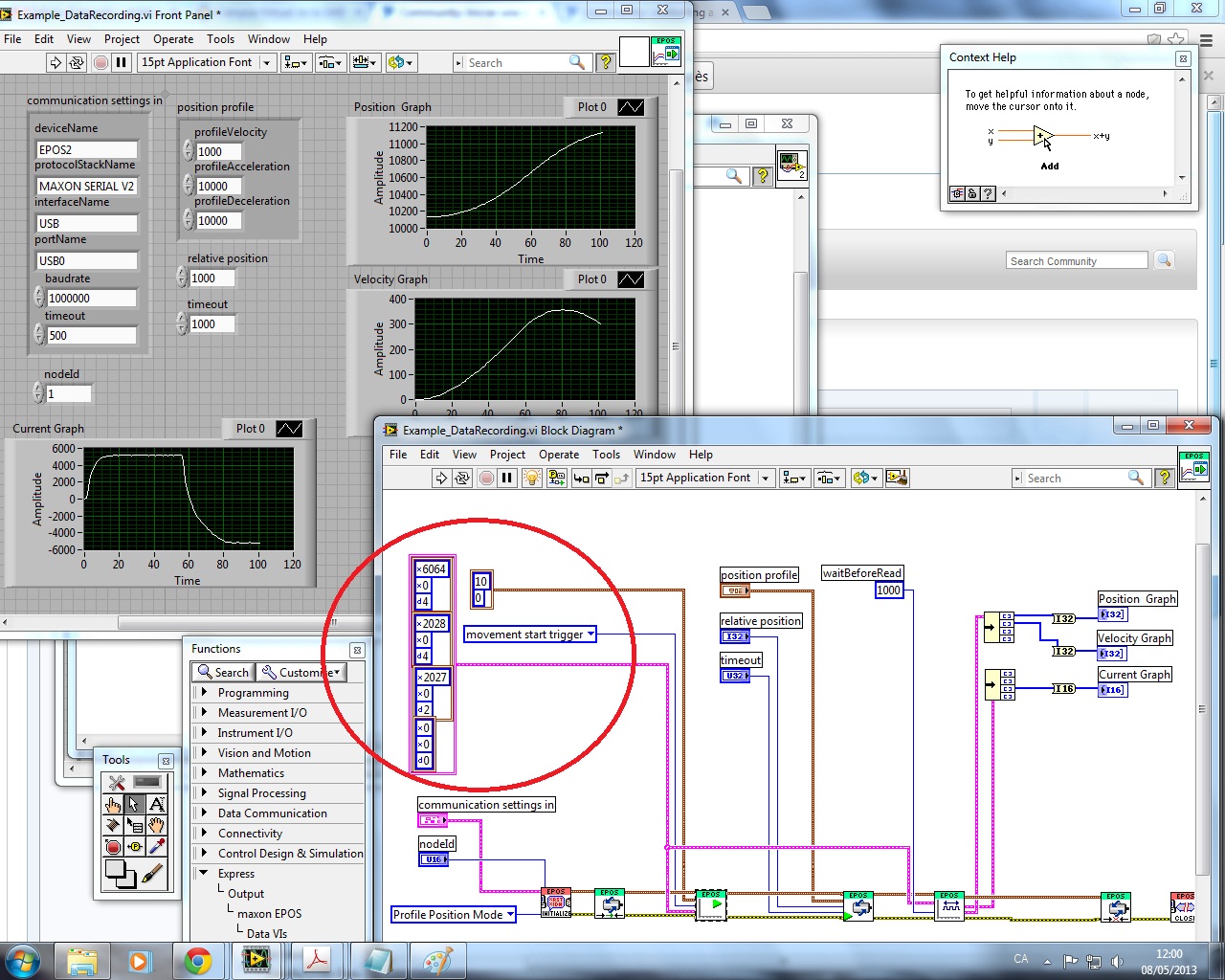
I tried a few examples from the library of the EPOS and I would like to know how this sample works and works to save the data.
Idon't ' tknowwhatdoestheparameters, thatthereareindecircle, means.
I would like to draw the Position, speed and acceleration. Somebody can explain to me how it works? and what is the function of the numbers in the cluster?
Thank you.
Best regards
Xavi
Hi Xavi,
You should ask Maxon to explain their software. Or read the manuals they offer...
Motors with a logic generally use a communication scheme registry. You write to register to set parameters, you read some registers for current parameters/values of the engine. Each cluster in this array describes one of these registers/parameters, such as the first with registry address x 6064, x 0 and d4 value. These settings seem to resemble specifications CANopen CiA!
I can't open this VI because it's the version of LabVIEW, but probably you will find labels on the control of entry of this Subvi. Read the labels...
-
Helps the acquisition of photon counter data using LabView 12
Hey all,.
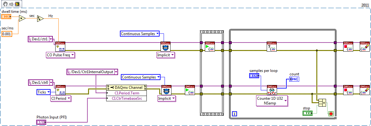
Student graduate Chemistry here new to LabView and are looking for some help moving in the right direction. I'm looking for help with connecting my meter to 12 LabView for data acquisition of trace-fluorescence photon PerkinElmer SPCM-AQR-14 (now owned by Excelitas Technologies). I just want to be able to acquire number of photon counts vs. time. Currently, I installed a PCI-6601 and use a BNC-2121 to connect the BNC of the sensor output. The detector has a pulse output digital TTL with 30 ns pulse width, and by contacting technical support on this issue, I was told that this pulse width was too short to always detected by the 6601, but can still go ahead and give it a try. Basically, if everyone is familiar with how to start with this configuration, ANY help would be greatly appreciated. As I said I'm all new to LabView and am currently spend all my spare time reading manuals and help files.
Please let me know if you need any kind of information to make me understand what I'm doing.
I would say something like this:
A measurement period the registry account out of the entrance of the samples as well as gives the meter. You will basically measure the 'period' of your sample clock fixed regarding ticks of the external photon signal.
According to the downtime, you may need to re-read several samples per loop so that the software can keep up with the incoming data. Also, the first sample is not useful because it represents the County between the software from the task of entry of the meter and the first clock signal - you should disregard/erase the first sample (or if you want you can set up a trigger to begin arms).
To do the same thing by using an edge County task would require using both the sample clock AND a counter reset signal - this not is not supported on 6601/6602 (even if it would be possible to set it up that way on a device of STC - 3 as a series of X).
Best regards
-
How to view mdsplus data using labview
I posted this question in the Council of Labview, but seems that nobody does it so far. I don't know what is the best place to ask this question. So I reposted here. Thank you very much.
I am a newbie to Labview. I'm writing a few vi to display and write data to Mdsplus. I downloaded Mdsplus(labview) can discover Mdsplus functions, like mdsconnect, mdsput, ect, in vi to call a library function. But I have no ideal how to use it. I tried to use the Mdsconnect function to connect to a machine, but it still gives me an error like: Labview: an exception occurred in the external code that is called by a call library function node... I was looking for help on the internet documents, but could not find anything useful. Could you please help me with this problem? If you have examples of these vi, or teach me how it, it would be very useful. I'm using Labview 8 (windows). I would appreciate your help! Looking forward for your reply.
Oops,
I attached properly in the previous post.
Greg
-
[BUG] TestStand 2013 receives corrupt data to LabVIEW adapter if the cluster contains waveform array
Hi all
I am having trouble with the corruption of the data. My minimal test case is below.
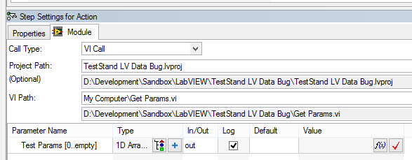
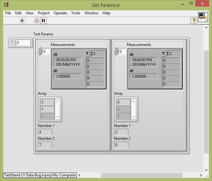
I have a VI that returns an array of clusters. My TestStand sequence simply call this VI and connects to its output:
When I run the (with my open VI) .seq file, I can see the update of the Panel before LabVIEW with expected values:
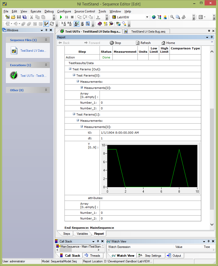
However, TestStand receives all these values. Waveform bays have the correct values, but everything else is empty / null:
If I delete my typedef waveform table, all elements of the cluster are correctly registered by TestStand.
I've attached an example of test (2013 TestStand, LabVIEW 2013) case.
Any ideas on how to make it work?
Hey JKSH,
Thanks for the detailed on this report. I looked into it a little bit last week.
I think that it is closely related to the 206892 of CAR, which describes a problem where data will not appear on the report unless a property or variable is specified for the output waveform parameter. However, this does not completely cover your case, because you see incorrect digital data in the row with the waveform of your cluster. I filed 462209 CAR for that matter, and we will investigate it more thoroughly.
This problem only affects data that appears "below" the waveform in the cluster. In the case of the sample, if you put the waveform as the last element of the bunch, I think that it works correctly. I know that your real data could be more complex than this example, but this workaround solution would help in the meantime? You could also consider separating the waveform of the rest of the data, that would probably work too.
As I said, please let us know, and it is classified in our system now for a developer to investigate the matter. Please let me know if solutions are not appropriate for your application, we would be happy to know a little more about your overall use case order to work around the problem.
-
Acquisition of data in LabVIEW FPGA
Hello
I'm working on LabVIEW FPGA where I need to acquire data from a source and take the average. One way to do that is to continue to add each new signal to the oldest f sum and then averaged.
However, I would like to keep all of the incoming values in a file and save it. But when I tried it doing so, it gives an error message saying "table size cannot be changed. With this constraint, I am unable to write the data to a table.
Please suggest.
Thank you.
You need different acquire data, pass it to the RT, then sign in here. Impossible to use build table the FPGA as FPGA will not allow dynamic allocation of memory like that. You must preallocate the table then use replaces the subset of the table. A better way is to use DMA FIFOs. Have a look at the FPGA examples in LabVIEW for data flow. Then, on the RT, you can simply add in your files logging functions.
-
data transfer labview to the web app server
Community of LabView greetings!
I have what I think, it's a simple question:
How can we transfer (real-time) and store acquired data (e.g., time, temperature and so suite..) of a labview VI to a server over the internet so it can be used for a mobile application.
Thanks in advance!
You will need to your data in your LabVIEW application on a server:
-Customer HTTP screws
-TCP/IP
-WebSockets
Server might have a LV application on it, or you can use a web server with a scripting language (for example PHP/ASP/Node.js).
You will need to write something on the server to listen to your LabVIEW application and contain the data :
-Database
-File
-Memory
You will need to write a few API/interface for push/recovery of data for example JSON/POST/XML - take a look at 'RESTful API.
The choice of one of them to go for depends on how 'real time' you're talking about - how often you want to update data, latency, etc..
If you don't want to do it all yourself, there are 3 third-party vendors that can store data in this way for you - there is a free (but limited) race one by SparkFun - https://data.sparkfun.com/ but I don't know there are other services.
-
How to read data from the unit to acquire data with LabVIEW
Hello everyone, I'm new with LabVIEW and I need help. How to build LabVIEW program to read and store the data acquisition unit temperature data. the data can be any store such as Excel or a text file? Thank you.
Start passing by examples of LabVIEW. Go to help-> find examples. There are several examples here just for the analog input and then even more for logging data to a file. After that, show us what you have and we can guide you a little better that way.
Maybe you are looking for
-
Symbol of the three discs stacked to the left of the power button on the front of the CPU
Pavilion p7_1070t CTO desktop PC What is the symbol on the left of the power button on the odf before the CPU? It looks like three stacked discs and a light under the symbol flashes?
-
From the control panel NVIDIA Win8.1 update does not work
Since the system op Win 8.1 update, I am not able to get into the Nvidea Control Panel. I get a message that are not connected. I got the card Nvidea my main source for the monitor. Help appreciated.
-
can I have 2 iPhones using the same account iCloud under the same roof?
My husband has an iPhone 5 s. He has recently upgraded to 9.2.1 operating system and asked to add iCloud account. He used my password. So now he has 2 iPhones on the same iCloud account. This will cause problems with the use of the phones?
-
I need up to 7 separate channels for this so each pump can be driven independently. Can anyone suggest what equipment to use to achieve this? George
-
How to install 64-bit on a 64-bit OS
I try to install Labview 2011 SP1 evaluation on Windows 7 64 - bit OS. When I choose the directory to install it automaticaly points me to the 32-bit compaibility folder "Program Files (x 86)". I think that this isntall the 32-bit version of Labview.