DC motor NI SMU-1071
Hello!
I use actually NI SMU - 1071.The input source that's it but my requirement is power to the top of my SMU by DC Input.Can u suggest any solutions of distribution of power as the converters DC / DC or modules with multi voltage levels meet the power requirements of SMU.
You will need a converter to do this. We do not sell these and so I can't give a specific recommendation, but you want to make sure that you do not have an inverter of low quality. It can cause problems if the THD (total harmonic distortion) is greater than 5%, or has a single harmonic with THD 3% higher. It is also the standard for sockets in the United States.
For this chassis, the max power is ~ 250W, so I would say that can handle at least get 300W to reflect losses and the environmental conditions.
Tags: NI Hardware
Similar Questions
-
APS Shaker and amplifier work with SMU-1071
Recently, we bought a shaker APS 113 and 125 APS amplifier for our new research project. We want to use NI-SMU-1071 controller system to control the shaker via amplifier.
NEITHER SMU-1071 > APS-125 amplifier > APS 113 Shaker
APS asked us to use Spektra VCS 403 (Vibration Control System) for this case. When we tried to use this software, there is an error in "open loop". But all things related very well. Amplifier and shaker do not work.
The seller company has no effective technical information. Please let me know your solutions, thank you.
Again, the 1071 is just a chassis. There must be some specific cards in it and you have not yet identified these cards.
In all cases, you will need to obtain assistance from the supplier of the custom software unless you intend to write about something else and need some help with that.
-
Where to find connectors for map plugin SMU
Can anyone help with information on the XP4/XJ4 connectors for SMU: numbers of appropriate provider type?
We want to make a personalized card to plug into a chassis SMU-1071 - but only a need the 3.3V power supply to the chassis. But after a long search, I was unable to find a number type for this connector. XJ4 is the smallest but of course all types of connector will do as they have all of the power pins.
Hello the heel.
I searched in our internal documents, and according to my findings we use ERNI as a manyfactor for our connectors.
Also, since you want to design for own PXI card, you might be able to find useful information in the PXI specification.
I hope you can use this information.
-
What should I install to control a scanner through a VI
I have a PXI-5122 card in a chassis SMU-1071 connected to a PC with LabVIEW2014 installed. And it can work under the control panel front of the NOR-SCOPE. Now I would like to taste signals and save them in files repeatly. But I can't find the example codes VI for SCOPE or scanners and downloaded from the internet example codes cannot be implemented as there are always a few Subvi failed.
Is there something more than LabView and NOR-necessary SCOPE?
Thank you and Merry Christmas!
Qubit
Qubit,
Do you have what version of NOR-SCOPE installed?
Support for LabVIEW 2014, to version 14.0 or newer.
http://www.NI.com/download/NI-scope-14.0/4826/en/
You can find examples under the Start Menu
Applications-> National Instruments-> OR-SCOPE examples of LabVIEW 2014 (32 bit)
the links to
C:\Program Files (x 86) \National Instruments\LabVIEW 2014\examples\instr\niScope
on a default installation of 64-bit Windows.
-
Hello
I want to use PXI-5105 on SMU 1071 chassis for strain measurment by conneting the strain gauge by the to 5105 wheatstone bridge circuit using BNC cables. I'm using Labview for the same thing.
(i) I get the variable noise (0,008 to 0.010 V) with no connection to the input channel.
(ii) I'm unable to balance / minimise the noise to zero by subtracting signal from one channel to another (differential input).
Data acquisition parameters:
Input voltage: 5V by DC power supply
All cables used are sheathed in copper cables
Sampling rate: 5ms / s
Number of samples to read: 2000
We worked on the reduction of noise for a long time. Any help will be much appreciated.
Thank you
Vinod
Hi Vinod,
Keep in mind the accuracy of the unit 5105 is specified to +/-2mV.
Also, you can check that your device has been calibrated on the outside and in his external calibration cycle.
When I watched a 5105 digital signal in a similar setup to yours, I saw the same kind of (about) + / 2mV noise. I don't think this is unexpected. Especially if you let the front end of your digitizer not completed, it could recover the additional ambient noise.
Why you choose to use this scanner for a measurement of the strain gauge? There are several other products OR Lane County and specifically designed for measures of constraint. Here are a few resources:
Strain with gauges
http://zone.NI.com/DevZone/CDA/tut/p/ID/3642
SMU-43xx Bridge Module Product Pages
http://sine.NI.com/NIPs/CDs/view/p/lang/en/NID/208288
Dynamic signal acquisition board
http://forums.NI.com/T5/dynamic-signal-acquisition/BD-p/100
-Andrew
-
FPGA VeriStand personality is late? and latent FPGA data processing
I use a FPGA 7853 (only) in a SMU 1071 chassis with a controller 8135 and run VeriStand 2013 SP1. At the end of my test, I want to ensure the integrity of the test, which includes the audit of the FPGA interface is never late.
I first thought to expose the terminal 'Is?' late as a channel, but then I noticed it isn't really an account, it's just a flag. In addition, it seems that this flag is not locked, it does report by iteration of loop interface. This makes me think that I alarm an VeriStand on the later is for VeriStand FPGA interface design? channel. Am I correct, and if not, how NOR have I use East late? terminal?
As the DMA in the FPGA nodes then never expire, there no sense watching the Timed Out? terminals on the FPGA. But the effect of a timeout will appear in the East towards the end? Terminal Server. I'm tempted to change the end is? U64 to a real number in the number of late? the defined indicators synchronize to the host VI. is there a reason to not do this?
How VeriStand manages a FPGA end? If the RT side of the DMA buffer became more complete, data from the FPGA would be more latent, which could lead to the instability of the system. Hopefully the VeriStand engine should purge the latency of the data, but I don't see anything in the FPGA interface which would facilitate this.
Thanks for your help,
Steve K
Hey Steve,
If the PCL NIVS reads this flag as true, it incrememnts the County of HP system channel.
For the question of FIFO depth: The PCL is always expected to read and write a # fixed packages each iteration (as defined by the XML) and FPGA always reads and writes the same number of packets of each loop of comm iteartion and since the timeout is set to-1... orders may not be combined. Packets act as a handshake.
-
Project Explorer can not detect my PXI-7952R
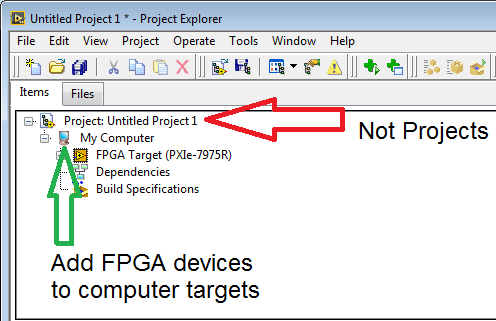
I use PXI-7952R and SMU-8115 in a chssis SMU-1071. When I opened MAX, my PXI7952R camera seems to be detected (if I'm not mistaken). However, when I try to open a new FPGA project, the Project Explorer can't detect it. is this a configuration problem or the device?
PS: I am really new in this field.
If you want to add a remote target of a project, you right-click on the project and select new > objectives and devices like you were doing it. However if you want to add a FPGA device, you select the target who has access to the FPGA, just right click and select new > targets and devices. In this case, you should be good by clicking in the project is 'my computer '.
Also make sure you have installed NI FlexRIO.
-
PXI-8513 appearing does not in MAX
I have a chassis NI SMU-1071, with embedded controller SMU-8100, DAQ, PXI-6229 and PXI 8513 CAN / XS.
Today I tried to receive SOME messages by using the XNET Read.vi and Session.vi to create XNET but when I wanted to specify an interface, he couldn't find all the interfaces, while the VI is located on the remote system and the PXI card appear in MAX I have checked my drivers and noticed that I was running NOR-XNET 1.4 I decided to update to 1.5, hoping that would solve the problem, which he did not.
When I opened MAX after the update, it detects the chassis, but it no longer detects the card PXI8513... He appears on a tab separated from XNET devices, but it has now disappeared. When I open the tab "Display Slot" of the chassis, he said slot 3 is unknown/Emty, although it houses the XNET card.
The software running on the remote system is the "NI XNET 1.1.1", this could be the problem and if so, how can I change this?
After reflection and reading this guide of errors (http://zone.ni.com/devzone/cda/tut/p/id/5403) I figured out I don't update the drivers on the target distance.
After that I updated the drivers through the software tab of 1.1.1 and 1.5 everything works fine now.
-
Hi all
I'm doing some tests with LabVIEW and I want to send the signal to analog voltage to a PXI-6229 (the chassis is an SMU-1071). I would like to know if I should add, in test programs I have, all controls to make the connection between Labview and the control. For example, to describe to which connector in the PXI-6229 cable is connected to (it has only connector 0 and 1)
Thanks in advance,
Francisco
Out of the actual analog channels and which connector they are, are defined by the task you created in MAX, the project or the VI. Somewhere, you specified ao0, ao1, etc. and the pxi slot number. No other information in addition to what you already have is necessary.
-
acquisition of signals from multiple cards simultaneously
Hello
I am trying to acquire the signal of my cards OR PXI simultaneously but having some difficulties to implement which.
Here is my configuration:
Installation of equipment:
(1) chassis NI SMU-1071
(2) map of NI PXI - 4461-2 I / P and O/P 2
(3) map of NI PXI - 4492-8 I / P
Here is the acquisition code I wrote:
The problem is that when I use the I / P channels on the same card (4461 or 4492) then, the code works well, but if I use the channels of entry on two simultaneous cards then I get an error message:
"
200106 error occurred at DAQmx Read (analog 1 Wfm NChan NSamp d) .vi:
Possible reasons:
Property must have the same value for all channels on the device.
Property: RefClk.Src
"
I tried to set the clock reference to "The clock on board", but I still get the same error.
What should I do to reslove this problem?
Thank you
Ritesh
Hi Ritesh
Have you tried to import a common clocks ref for 2 boards? This is not supported by all devices, but for those that you combine, this should be confirmed as you can see on page 44 of this document.
WenR
-
PpiEnableInterrupts returns error "Invalid Length specified"
I work with IVI VISA PXI plug in modules OR (defined by IVI-6, 3). Almost all of its functionality works perfectly - like module list, attributes and access the memory space, etc... The only problem I got is interruptions. 'PpiEnableInterrupts (__in PpiHandle handle, __in ViUInt16 queueLength)' returns 0xbfff0083 'specified length is invalid error code. " I tried with different values of queueLength... or actually, I did a sweep from 0 to 1024. in all cases, the same error status is returned.
The material I work with is the following:
* Chassis: NOR SMU-1071
* Module system: Ni-SMU-8360
* Module that I work with the help of the plugin: OR PXI - 6509 (DIO)Versions of the software:
* OR VISA: 5.4
* NI PXI Platform Services: 4.0
IVI VISA PXI of the NOR plugin (NiViPpiP.dll & NiViPpiD.dll): 5.4.0.49152I know that PXI-6509 generates interrupts...
Any ideas why PpiEnableInterrupts does not work? Maybe its because the module is PXI SMU not?
Dear bartek-o,
I searched our resources to see if we have a better explanation for this error. What I've found, is that it is especially caused by the configuration of the interrupt functionality error.
Please consult this document: http://www.ni.com/white-paper/3142/en/There is a section that says:
Tip: If you write an instrument driver, let generates interrupts disabled during the initial development phase, even if you plan to implement of the interruptions. It is often useful get the basic functionality of driver before trying to add support for the interruption of work. Interrupt management can be added to the. INF file by running the wizard VISA Driver Development again.I suggest that you open VISA Driver Development Wizard and reconfigure the interruptions component generates. It is possible that it is not properly set / and / or not allowed at all.
Please get back to me if you could try this!
Best regards
Peter
-
DAQmx read results 2 ms/s in high CPU usage
I have an application that reads the 32 channels of 2 ms/s analog input signals, at the same time. The actual hardware will be: SMU-8135 Win7, chassis SMU-1071, 2 x SMU-6368 (16 channels). The SMU-two 6368 will provide 32 channels data acquisition.
I don't have the material at the moment, but I've been estimate the processor on the alternative configurations needs, because I have concerns about the use of the CPU to data acquisition high speed. Two alternative configurations are:
(1) SMU-8133 (quad core) WinXP, SMU-1062 q, PXI-6133.
(2) PXI-8106 (dual-core) WinXP, PXI-6133, PXI-1042.
Note: PXI-6133 supports high speed HAVE 2 ms/s, at the same time.
I wrote a simple continuous data acquisition software to allow me to compare the CPU usage. The sample rate and the number of channels are configurable. What I found is:
(1) at low sampling frequency, for example 100 kech. / s, the CPU usage is minimal on both configurations (bicoeur or image), regardless of the number of channels is 1 or 8. The reading of the CPU was about 1-4%
(2) at high sampling frequency, for example 2 ms/s, what is the number of channels used, either 1 or 8, the CPU utilization was 50% for dual core and 25% for the quad core, IE. a full core has been fully utilized.
(3) the passage of the low use of the processor (<5%) to="" high="" cpu="" usage="" (="">45%) increases when the sampling rate is rather steep and shows interesting channel-dependence (note the following has been achieved with a PXI-8106 controller, dual-core).
- @1 channel, it happened between 950 to 970 k
- @2 channels, it happened between 470 to 480 k
- @4 channels, it happened between 230 to 240 k,.
- @8 channels, it happened between 120 to 130 k.
This model reminds me of buffer length related question but I double checked a sufficient length of the buffer was used. He suggested also, surprising a few traffic jams occurred when the amount of data increases up to certain level.
My question is, is this a problem with this particular card (PXI-6133) or driver DAQmx (9.5.5f4). How the problem is when I'm doing an acquisition of 32 channels?
For your information, I have attached the benchmarking software.
Thank you!
Donghui Yin
I followed this example code (see link below) and used based on events DAQmx, now the excessive CPU utilization problem has been resolved. Playback from the CPU is now less than 10 percent, while it could be 50% (in the case of dual-core) or 25% (case of hearts) at the same sample rate and number of channels.
-
Increase in the rate of sampling with external clock
Hi all
I have hardware DAQ-SMU-6361 and SMU-8360 controller in an express chassis SMU-1071. My 6361 maximum sampling frequency is 2 MECH. / s. But I want to use my daq with higher sampling rates. After going through the various positions, I decided for two options to increase my sampling rate. You must connect a 5 MHz signal generator to use as an external clock. Another is to use the timer to synchronize PXI Chassis
My question is
(1) what is the limit to the frequency that we can use as external clock for data acquisition? Which parameter is limiting the performance of the ADC, if we use the higher clock frequency signal?
(2) I also learned about an option called 'base time in PXI Express chassis'. can I use this option? Someone please give me a link to a good tutorial on the basis of time in a single PXI Express chassis?
(3) SMU-1071 chasis, 100 MHz differential clock. Is it possible to use it as a clock to my DAQ 6361 signal?
Concerning
Vaidhin.
HI Vaidhin,
The article mentions the background basket clock as a possible means for synchronization, but this is accomplished using it as a phase reference clock - align the oscillators on board your hardware DAQ which are then distributed down to produce the sample clock. You may not use background basket clock or time base on board directly as a sample clock (on the one hand, these signals is much too fast).
Measuring 1 MHz with a DAQ hardware 2 MHz could not give you what you expect. You will get 2 points per period of your entry - it's just at the limit to avoid aliasing of your signal and of course do not a good characterization of the shape of your signal. You might be able to push the card in slightly beyond 2 MHz but not significantly enough to make a huge difference. You are right that if you have sounds at higher frequencies could be an alias down in your signal. Any noise above ~1.7 MHz will begin to be eased by a bandwidth limited the 6163 (there is a chart in the specifications , showing the bandwidth). If you have between 1 MHz (signal) and ~1.7 MHz noise, you might look into an external filter, but again you are always sampling very slowly to be able to characterize the shape of the signal.
The next steps to the top (in terms of sampling frequency) would be as follows:
4 MHz: SMU-6124
10 MHz: PXI-6115
There are currently no products that use the same DAQmx driver who can enjoy beyond 10 MHz, but NEITHER there also a range of scanners that you may enjoy a lot faster. If you are interested in sampling up to 100 MHz, you may consider looking in the SMU-5122- there are also faster scanners available, but these are probably not necessary for your application.
Best regards
-
PXI: Request username and password
The deployment of the system definition file PXI system asks user name and password. Is there a way to bypass or confirm that programmatically? Can I disable this Max?
VeriStand and LabVIEW 2015 with SMU 1071
OK, with this method I can solve it: set the empty password. https://forums.NI.com/T5/LabVIEW/remove-password-from-RT-controller/m-p/3183622#M921345
-
Hi all
I am having some problems of data collection with a VI that I put together using LabVIEW 2010 and DAQmx 9.5. My DAQ hardware is an SMU-6341 in a chassis SMU-1071. I have a single VI which runs through all the tasks and controls that are channels in each task. Channels are then moved into a knot of channel property to check the type of channel. It allows me to adjust program which DAQmx read that I use to read data from the buffer.
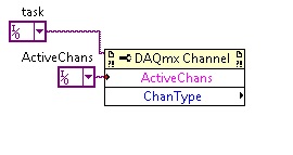
I get error code-200428 stating that the task I'm passing in the channel property node is not valid. It then gives me the CHANNEL name that the task is not valid. Am I assuming I can switch from channel at the entrance to a property DAQmx node reference? I know that the task and the channel of the task are configured correctly because I can see the voltage on the digital output terminal.
Any help with this would be greatly appreciated.
Best regards
Ryan
Types of channel properties are weird.
You must connect the task in the upper left entry of the channel property node, not the channel.
Then choose the 'Active channel' property and add another property to the node which is chanType. Son of your channel in the first and get the chantype of the second property.
Maybe you are looking for
-
SSD for transfer to hard drive does not
So I read a lot of similar questions and nothing isn't really working as they say should I'm on a Windows 7 system, trying to move my music library on my hard drive to save space, and I got far enough away that I consolidated things and copied the fi
-
How can I find my serial number?
I download a game, and he needs my serial number. I have no idea where to find it. Thoughts? AQ
-
How to run the command sfc runs on Vista
My dept here reimagee IT my computer today and I'm unable to access my WD external drive. WD has suggested to get help with the sfc command before possibly spoil my data. Anyone have any ideas? Thank you
-
Click on the link inside the non-Focus field
Hi all I use an ActiveRichTextField non-focusable because the field is part of a larger container making screenshots click on itself - not the children. This was done to make it easier for the user to scroll up and down on a list of text fields (do n
-
5.7 LightRoom supports the RAW of Nikon D5 file?
I use Lightroom for Mac 5.7. I'm not able to import (in NEF format) pictures taken by the camera Nikon D5. LR5.7 will support it? and when?Thank youAndy