PXI-6229 + LabVIEW
Hi all
I'm doing some tests with LabVIEW and I want to send the signal to analog voltage to a PXI-6229 (the chassis is an SMU-1071). I would like to know if I should add, in test programs I have, all controls to make the connection between Labview and the control. For example, to describe to which connector in the PXI-6229 cable is connected to (it has only connector 0 and 1)
Thanks in advance,
Francisco
Out of the actual analog channels and which connector they are, are defined by the task you created in MAX, the project or the VI. Somewhere, you specified ao0, ao1, etc. and the pxi slot number. No other information in addition to what you already have is necessary.
Tags: NI Software
Similar Questions
-
PXI-6229 gives error 200019 when they acquire more input 25ch
Hello
I'm trying to measure voltages with the PXI-6229 32ch and PXI-8106.
If I build attached VI and it works very well when acquiring less entered 26ch
defining "Physical channel" VI "PXI1Slot2 / ai0:25".
I think that the PXI-6229 32ch of analog input, but it gives an error-200019
When I tried to measure more 25ch entry affecting "Physical channel" "PXI1Slot2 / ai0:26".
Please help me solve this problem. Thank you
Moussa
Hello Moussa
Thanks for posting your question on our discussion forum.
I'm Junichi Terao NOR Japanese.
I looked in the PXI-6229 and your VI spec sheet, and it seems that the error is caused by the sampling rate you use. Please look below the PXI-6229 (page 1) specifications:
http://www.NI.com/PDF/manuals/371290g.PDF
6229 PXI for multi channel maximum sampling rate is 250 kech. / s (aggregation). If the maximum sampling for each channel can be calculated as follows:
FMAX = 250 k / number of channels
When you set 26 channels and sample 10000 s/s, it is greater than 250 kech. / s. This could be the reason for the error.
If you plan to use 32 channels, each channel sampleing rate must be less than 7842Hz
Sincerely,
Junichi
-
Problems of synchronization of the sample clock with a frequency of a PXI-6229 counter!
Hi all, I'm having some problems with the synchronization of a frequency meter connected to a liquid flow meter (sensor only have 1 open collector output) with the sample of a PXI-6229 map clock. Someone there willing to give me a little help here would be appreciated?
The problem is that the reading of the meter in the whole loop blocks until the time-out period.
Suggestions for an alternative approach would be too good...

Source code attached.
BR,
/ Roger
It sorted another way!

-
How to control NI 2503 PXI using labview?
Hello
I am vishal.
I have a job where I have to monitor the temperature of the various components.
LabVIEW platform is used to make a software that takes the output of thermistor through NI PXI 2503 multiplexer and converts it into digital
using or pxi5152 digitizer.now I have to control the two instruments of this and take values of the digitizer.
but the problem is that I don't know who you screw to control these instruments, because I do this first time.
I just know that the NIDAQmax screws can be used, but do not know how to use it.
Please give me a little early to make this program.
Thank you.
You can find this useful: combined with the switch Modules OR PXI high-speed digitizers measures. Basically, OR-Switch is used to control the multiplexer.
-
S/W-chassis PXI RTOS by MAX load
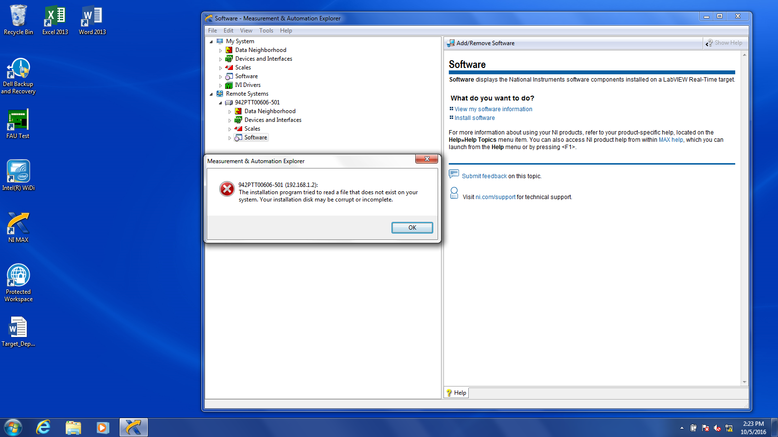
I have a chassis PXI with LAbview 2016 RT OS on it with Windows 7. When turn the PXI chassis, I get a message that "no software is installed. When I try to intall software via MAX from a remote computer, I get the following message. Can someone tell me what this means? If I have to install the software locally (IE bunch the PXI chassis in WIndows), where can I install the software (C:\ drive, which Windows or the drive D:\, which has the RT operating system on him)?
Bob,
Thanks for the help.
In the end, had to reformat the drive controller and who took care of the issue.
-
PXI-8513 appearing does not in MAX
I have a chassis NI SMU-1071, with embedded controller SMU-8100, DAQ, PXI-6229 and PXI 8513 CAN / XS.
Today I tried to receive SOME messages by using the XNET Read.vi and Session.vi to create XNET but when I wanted to specify an interface, he couldn't find all the interfaces, while the VI is located on the remote system and the PXI card appear in MAX I have checked my drivers and noticed that I was running NOR-XNET 1.4 I decided to update to 1.5, hoping that would solve the problem, which he did not.
When I opened MAX after the update, it detects the chassis, but it no longer detects the card PXI8513... He appears on a tab separated from XNET devices, but it has now disappeared. When I open the tab "Display Slot" of the chassis, he said slot 3 is unknown/Emty, although it houses the XNET card.
The software running on the remote system is the "NI XNET 1.1.1", this could be the problem and if so, how can I change this?
After reflection and reading this guide of errors (http://zone.ni.com/devzone/cda/tut/p/id/5403) I figured out I don't update the drivers on the target distance.
After that I updated the drivers through the software tab of 1.1.1 and 1.5 everything works fine now.
-
PXI-6534 replacement by SMU-6537
I am currently ordering and receiving data from a device to measure with the PXI-6534, LabVIEW and DAQmx on Windows.
Can I replace the PXI-6534 by an SMU-6537 without having to change anything to my hardware (will be in other words, the cable connections and advice sheet be compatible)? If so, the code written to communicate to the PXI-6534 will be reusable with the SMU-6537?
Thank you comments or pointers.
X.
I'm really sorry, but I forgot to mention in my previous post that there is indeed an adapter that will allow you to use the same block that you used with the PXI-6534. You can find more info on this adapter cable on this link:
-
Using the sensor IR of Mikron m770s with labview
I use a detector to spot m770s Mikron infrared with a chassis PXI and LabVIEW. The material I have is m770s (4-20ma output), a current of CSC-C120 input connector module, SCC-68 of e/s, NOR-PXI-6221 M series: DAQ with DAQmx and a PXI-OR-1033 chassis.
I tried to set this up, Max and it seems to work, but when I tried to extract actual data from the probe in LabVIEW, I got nothing.
I hope someone can point me in the right direction.
Thank you!
Hi PollardVT,
A slowly increasing way continuous signal would be an expected behavior for a terminal not connected to a data acquisition device (more information in this knowledge base). I would first check that everything is wired up correctly and there is no bent pins or loose connections.
You might want to try to replace the entry on your SCC-CI20 resistances. Information on how to do it on page 4 of the Manual of the SCC-CI20is provided.
If this is not enough, I would check to make sure that the combo of 6221 / SCC - 68 data acquisition work properly. The SCC-68 manual describes how to set up the SCC-68 as a Terminal screw (on the bottom of page 28). Choosing to use the SCC-68 as your Terminal gives you access to all the entries on the DAQ hardware. I would try to connect to a known voltage source (8 and 14 pins are + 5 Volts) to one of the terminals of input analog to see if you can measure a voltage signal. This will allow to check if your 6221 and your SCC - 68 are connected properly.
Let me know how to work these suggestions. If you still have problems, you could send a screenshot of your hardware configuration in MAX?
-John
-
LV RT2010 on PXI-8145RT - cannot upgrade the BIOS
Hello
My lab has a pair of PXI systems controlled by 8145RT PXI and LabView 2010 because we have not upgraded for awhile. As far as I know, this controller should be usable with LV2010 RT.
However, when I try to install the software on the target using MAX, I get a message informing me that the software I would like to install (LV - Rt 10.0) is incompatible with the operating system loaded on the machine. The ethernet driver install without problem, for what it is worth.
When you try to upgrade the BIOS, I first got a message that the controller contains the version 10.2 and 10.3 version is available on the host. If I try to follow the upgrade procedure (jumper W2 bridged, of course) the controller sees a bit of business network, reboots, gets a little more traffic, and then MAX tells me that the update has failed.
I can see that the flash update program was transferred to the target and set as the boot executable, but clearly it was not entirely successful. Can anyone help with this? I upgraded to 512 MB CF card (which he has no problem using) and RAM 64 Mo - I didn't have an old 128 MB SODIMM autour. What is the problem? Starting with redirect series will help something? I have to build a null modem to make this work.
For anyone in a similar situation.
In the end, I decided to downgrade to LV2009 on my development machine and try things again. With the help of LV2009/LVRT2009/MAX4.6, I was able to upgrade the version of the BIOS on both of my controllers 8145RT - correctly we from 10.2 to 10.3 and 9.1 to 10.3. After that, I was able to install RT2009 + DaqMX + another need of the components on the controller for which I had updated size RAM and CF. There is not a lot of memory to spare, but the controller starts in LVRT(9.0/2009) and I have successfully deployed an application to test on this subject.
My application may require an upgrade to faster hardware in the end, but the 8145RT must stay a usable under LV2009 for simple tasks controller. I suspect that LVRT2010 would work, now that I got the BIOS upgrade, but I'm not inclined to test this right now.
As for the original question of the update of the BIOS fault, I'm pretty sure it is a bug in MAX 4.7. 4.6 MAX had no trouble to initiate an update to the exact same version as 4.7 was trying (10.3); I suspect that MAX 4.7 have not properly configured the CF environment to start the flash update program.
Hope this helps someone.
Jon
-
How can I call vi deployed remotely on target RT PXI host computer laptop
We have a system comprising a support real-time embedded pxi with labview real-time and a regular mobile host with labview. Interconnection is ENET. The two systems must be deployed I.E standalone runtime distributions. What is the best method to call s vi on the basket pxi from your laptop?
There are a lot of details to make it work, but I will offer a high-lvel description.
You can use VI server to call code on machines of RT.
For each application that you want to call the side RT create a source distribution. Those to the node RT then using the correct path on the RT node using VI server to open and run the target live FTP
Have fun
Ben
-
NEITHER 6229 Analog channel to generate the current
Hello
I use PXI-6229 to generate values of current analog output channel, but I get the following error:
"Physical channel selected does not support the selected property. Select a channel that supports the property, or select a property that is supported by the selected channel"
I tried with all 4 channels of analog output: ao0, ao1, ao2, ao3, but I got the same error with all. Also, when I run the examples OR to
'CVI\Samples\DAQmx\Analog Out\Generate Current\Cont Curr Wfm - Int Clk Gen' location, I get the same error.
Kindly let me know the solution for it.
Thank you
Priya.
Outputs analog 6229 are sources of tension - not a current source constant.
-
OR PXI-8196 target using a USB stick formatting
Hello everyone,
I use a PXI chassis with controller PXI-8196 and multiple PXI DAQmx cards. I need to format the hard drive on the target of PXI and reinstall the RT operating system as well as all other software. I am trying to restart the PXI with a USB bootable, but it gives me the option to format the hard drive.
Here are the steps I followed.
1. I created the disk bootable with MAX using the RT disc utilities > create Desktop PC USB Drive Utility (PXI-8196 does not have a floppy drive so I have to use a USB key)
2. I have connected a keyboard and screen to target to see it start.
3. I've also adjusted the sequence of boot as the boot option "USB HDD: LEXAR JUMPDRIVE SPORT" among those available in the boot sequence has the highest priority. (My USB is a USB of LEXUS so I'm sure that this particular option must be the first in the sequence).
4 but once I start my system. It does not give me the option to format (according to MAX documentation should give me an option to "format hard drive"). Here's what I see on the screen connected to the target
= = The output to the screen is bounded by these two rails =.
Boot mode safe of Romans...
Enter safe mode.
The IP address is: 10.10.10.2
_
===========================================================================
At the end of the last cursor keeps blinking and nothing happens
5. the 10.10.10.2 IP address is the address in the configuration I want to format and reinstall. So I don't know if he meant to keep automatically previous IP address.
6. to avoid the fact that there may be something wrong with the USB, I repeated the procedure as a whole with another USB drive. But exactly the same thing happens again.
Please help me it reboot with a USB port and format the hard drive and reinstall all software.
Thanking in anticipation.
Vivek.
Hello
Try this, go into the BIOS of the PXI, under LabVIEW RT to the startup configuration, change the Windows option / other OS. Then try what you are doing.
Let me know if it works for you
-
How can I get the digital power meter?
How can I get the digital power meter?
I use a method similar to the example below to measure the market factor using the inputs of a multifunction data acquisition meter. If the duty cycle is 0% or 100% for a given period, DAQ reading times out and returns an error. In this case, I would get the digital state of the counter of entry so I can put as cycle to 0% or 100%. I want to do it without knowing the digital port and line the entrance of counter... for example I would like to continue referencing DAQ/ctrX since I already have this information.
The application uses an M series: PXI-6229 DAQ and LabVIEW 2011 to make a system customized for VeriStand.
https://decibel.NI.com/content/docs/doc-12396
For the moment I wired the block diagram to add a case structure to check the meter ID and string constants to set the identifier of digital input, as they share the physical connection. As much as I can say that makes the specific code for the PXI-6229 (or any DAQ with only two counters that share connections with p2.1 and p) 1.4
I have attached the VI sub.
When the device is used with a different data acquisition, I can add the connection and/or separate control. Looks like at least one will be necessary given that the meter can only detect the edges... I think it was the piece of information I needed.
Thanks for your help!
-
HAVE multiple AO-synchronization-2 multiple while loops
Hi all
I want to characterize my RF circuit by using an additional narcotics control and map PXI-6229. I wrote a simple VI in Labview, which is almost similar to the example, multiple-HAVE-AO-synchronization, seen in LABVIEW. According to my VI, 4 analog outputs with different offsets dc, amplitudes and phase values must be generated to my RF circuit and 2 analog inputs must be acquired by this circuit simultaneously and continuously. But the problem with my VI is that I try to observe two diagrams at the same time to see the changes in signals generated and acquired. However, I don't see the two signals simultaneously. The second while loop, which belongs to the acquisition of analog signals, does not start while the first loop generates analog signals continuously. How can I synchronize these two while loops in order to observe the two parties in the diagrams?
I have attached my VI.
Thanks in advance.
T. Eray
Hi Eray,
I will be brief and I'll keep it simple. If I understand correctly, you have trouble with the data stream in LabVIEW. When you work in LabVIEW, you must understand the order in which the blocks (functions/nodes/structers) are run in LabVIEW - stream. Each block can be executed just at the moment where there values on each entry. This means that if the 2 blocks are connected with a wire, the 2nd block waits until the first ends its execution.
In your case, that means, this 2nd loop does not execute before the first loop (with the DAQ Assistant) ends its execution, because the son comes from the inside of the first loop, then they go to some DAQmx features and then DAQmx features they go to the 2nd loop.
In principle, what you could do is to put the content of the first loop, where you prepare the signal generated in the 2nd loop. Good course without the DAQ Assistant. Instead, you can use DAQmx writing in the 2nd loop.
Kind regards
Martin
-
DAQ cards not selectable, that listed in MAX
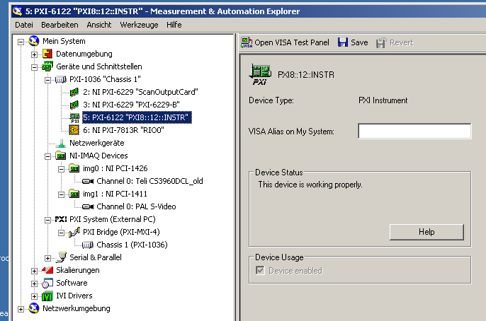
I have (re-) installing a PXI-6122 card on my computer. The device is then entered in the measurement and Automation Explorer, but differently from what I'm used to:
-It's another symbol than two PXI-6259 cards I have (see image below).
-It is not possible to create a task for the device using MAX because there is no such button.
In addition, in LabVIEW 2010 "device" or "physical channel" enumeration control, it is not listed (unlike the two PXI-6229 cards).
First of all, I knew that the card is broken. But it works correctly on another PC (with its own PXI chassis). Also, if I replace the card 6122 by another of the same type, the problem remains.
Then, I uninstalled all National Instruments software on my PC, deleted the "c:\Program NIUninstaller Instruments' file and some registry entries NOR related and reinstalled LabVIEW 2010 and device drivers. Now, the problem I had with the PXI-6122 now occurs for all three DAQ cards on the system (i.e., the two 6229 maps AND map of 6122): MAX icon is one that has the 'label PXI', tasks cannot be created in MAX and no device / or physical channels is displayed in the respective controls of LabVIEW.
Anyone have any idea how can I proceed?

Maybe you are looking for
-
Paginate a hard drive from a MacBook Pro of dead in an older Machine
HI, my problem seems to be slightly different than I've seen it comes here or elsewhere before. After a hard life, my early 2011 MacBook pro 15 "is dead. In recent months the usb Sockets have been unreliable and wifi no longer works, so a few days ag
-
GarageBand doesn't import not curls
I bought garageband on the app store and the loops do not work, it tell me "sulected stoftware instrument or apple loop is not currently installed on your computer. You want to install the full game? I tried several times...
-
No place to enter the password and user name
Until now I was using Skype without any problem and I accept all the automatic updates. A few days earlier, when I tried to log into my account, I had attached the log in page icon. There is no place to enter my username and my password. I have unins
-
Lenovo G460 - updating memory problems...
Hope you can help me on this one... I have a laptop Lenovo G460 with 2 GB PC3 - 8500 DDR3 SODIMM 204pin memory, 500 GB HDD, i3 - 370 Proxcessor and running Windows 7 Home Pro 64 Bit (Specfication Original I bought Lenovo) However since then I upgrade
-
HP C8180 record after reinstall. Why?
Do I really need to save again? I had to uninstall/reinstall to fix a connection problem. After reinstalling, it tells me to register.