definition of graph of the intensity to flashing causes crash LV2012
Hello
This VI crashes when the definition of flashing to TRUE, using LV2012, Win7 32 bit. I saw that there was a bug in 2004 , has not been set yet? Or am I missing something obvious?
Thank you
Danielle
Well Yes, still divided LV2013SP1.
I don't make any excuses for not acting, but I would image that flashes a graph of intensity is not something that they get a lot of complaints about the...
Mike...
Tags: NI Software
Similar Questions
-
How to use the graph of the intensity in the iPad data dashboard.
Hello
I use a graph of intensity in my vi main under a project of myRIO.
I created a shared variable of the 2D array. When I selected the variable in the ipad it does not show that he presents in the pc...
I want to mention that I have selected the multiplier as (= 30/255) 0.117647 in labview in pc
I use the version of labview 2015 myRIO.
and I am using iOS 10 in my iPad
can someone help me please
Hi adil,.
The graph of the intensity is not supported in the dashboard of data.
Kind regards
Denny
AE Singapore
-
draw lines on the graph of the intensity
I want to draw lines on the graph of the intensity.
I am already looking for some questions before.
I know there is a vi could draw line on the graph of the intensity by dragging the mouse.
But I need more precisely what set the length and the angle between the horzontal line.
The setting is very ideal for me. But I don't know how to use it in the intensity chart.
Is there anyone can help or give some advice?
Your example is not so great because it uses 100% of CPU on a kernel at any time, do nothing.
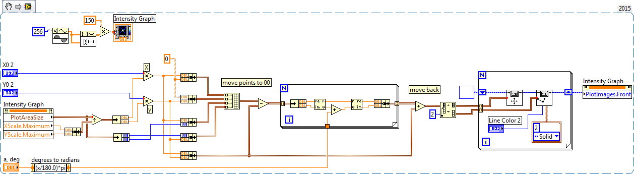
Here's a quick rewrite of my old example here. He draws an angle with the specified length and angle to where you click on the chart. This should help you get started. Modify if needed. (Also remember that trigonometry is much easier when using complex numbers
 )
) -
DateTime on x-axis of the graph of the intensity
How can the x-axis of a graph of intensity be configured to the DateTime data type, similar to the graphic waveform XAxis? You can set the FormatString DateTime MajorDivisions, but has no way of installing the x-axis values. Waveform curve has a foot (double [], DateTime, TimeSpan) function that will implement the XScale with the correct DateTime values, but the graphic intensity doesn't seem to have a similar capability. I tried to configure the graphic intensity YAxis MajorDivisions DateTime Format string and pass then the plot function Tick values for the yScaleStart and YScaleIncrement, but it does not work probperly. MS2012 release notes say that the curve of intensity has now an automatic formatting for displaying DateTime on axes X and Y. I tried to use this feature to test the DateTime X and the ability to axis Y; However, the function of automatic formatting is not available for the chart of the intensity. Any help is appreciated.
Thank you!
Jon
Hello
Try the following code piece.
            // Set the label format correctly            intensityYAxis1.MajorDivisions.LabelFormat = new NationalInstruments.UI.FormatString(NationalInstruments.UI.FormatStringMode.DateTime, "g");
            intensityYAxis1.Mode = NationalInstruments.UI.IntensityAxisMode.AutoScaleExact;

            double[,] data = new double[100, 100];

            for (int i = 0; i < 100; i++ )
            {
                for (int j = 0; j < 100; j++ )
                {
                    data[i, j] = (i + j) / (colorScale1.Range.Interval * 2);
                }
            }
            // IntensityGraph only understands double values. But graph can interchange the data value from different types using the DataConverter provided by NI.
            intensityPlot1.Plot(data,
                0,
                1,
                (double)DataConverter.Convert(DateTime.Now, typeof(double)),
                (double)DataConverter.Convert(TimeSpan.FromDays(1), typeof(double)));
It will be useful.
Habim stone
National Instruments
-
How can I specify pixels in the graph of the intensity?
Hello
I want to specify the number of pixels in the in the intensity chart. I have 56 values want to display. How can I do this?
Hi jerryvdk,
By specifying the number of Pixels, you hear, allowing only a specific land area size of the chart itself?
You can change this through the use of a property node.
Steps to change the plot area size:
- Right-click on the graph of the intensities.
- "" "" Scroll create "property Node" plot area "size" all items.
- This will create a property node that will allow you to change the property of area of the draw of the intensity card.
By specifying a space of draw of the 56 x 1, this would allow a 56px draw area size fate. Is that what you meant?
-
With the help of the graph of the intensity
Hello
Currently, I have a problem with the graphics of the intensity. I use the Toolbox of the time frequency in Labview. Currently, I am having a problem where I had to plot the spectrogram of the signal. I tried to maintain a plot of the spectrogram to 0 for 4S and another 4 s to 8 s. I'm trying hard to draw the graph of the two together, to form a parcel from 0 to 8 seconds, in the spectrogram. In addition, the time axis will continue to increases in 4S interval with a spectrogram updated. I wonder how can I realized by having two spectrogram with two different time interval to display a common conspiracy? Thanks much for the advice.
RDG
kengkc
Hi kengkc,
Correct me if I'm wrong, but you say that you have the data for the first 4 seconds of your acquisition (t = 0 to 4) and 4 seconds following your acquisition (t = 4 to 8) and you want to combine them into a plot? I guess that since you were able to draw in a graph of intensity to begin with, they are already in the tables.
If that's what you want to do, you can easily concatenate your arrays using the Array function build (which means to add a table at the end of another person). Add your function Array of build of the subpalette of the table and make sure that you right-click and choose concatenate arrays so that you get more dimensions in your resulting table. Then expand the function Array build so that you can wire your matrices inside.
Please refer to the attached screenshot to get an idea of what I mean.
I hope this helps.
-
Draw the new lines on the graph of the intensity
I'm trying to attract the XY axes by an arbitrary point on a graph of intensity. I can draw two lines across the image (suite of messages like this link below), but they don't really seem FDNE to the top one the coordinates I spesify. I know that I have to correct the fact that the vertical scale increases from top to bottom, but how do I draw lines to the (x 0, y0) position I spesify? It seems that the lines are superimposed on the image, but not related to the axes of the actual intensity chart.
http://forums.NI.com/T5/LabVIEW/overlaying-XY-line-onto-intensity-graph/TD-p/398963
but you need made "vertical mirror".
-
Fade colors in the graph of the intensity
Hello world
I did a program where I read a 2D array and draw this picture in a graph of intensity.
I was wondering if the colors in the chart weaken each other, preferably in a vertical position (columns). The idea is that digital data becomes viewed as a genetic profile.
I added a picture of the graphics path.
Thank you.
Without manipulating the table, no it's not possible. I had an idea about the exchange of idea to solve this problem, I recommend that vote you for it. Anti-aliasing or smooth intensity plot
As says the idea, see this post for workarounds.
-
Save the graph of the intensity under the film
I made a graph of intensity using the link below:
http://zone.NI.com/DevZone/CDA/EPD/p/ID/1050
I made a chart for 500 different images using 500 xls files. Now, I want to save these images in the form of a movie (avi, wmv, etc.). How can I possibly do? Help, please.
Hello Paritosh,
This will depend on the actual language and the function you use. Could you give some more information there?
I would check the functions available using the object browser. Searching for something as controllable or paintpicture.
-
How can I get my intensity graph to display the data of each electrode in a 9 x 9 table? I need to be able to see which box is which.
-
Table of standard color for the graph of the intensity
Hi all
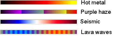
I am trying to change the color table of a graph of intensity of some tables in color standard, such as 'rainbow', 'gray', 'seismic', 'waves of lava","hot metal","purple haze", etc.. I can't find not "Rainbow" and "grey" somewhere for the examples, but not others. I tried to generate these color tables myself using the example «...examples\general\graphs\intgraph.llb\Create Table.vi IntGraph color, but the result was far from good.
Can someone teach me how to generate these color tables? Thank you in advance.
Kind regards
Mario
Hi GerdW,
I'm not sure of the exact way to do it, but I did a simple vi based on your idea. The vi to retrieve the color table I want in the table format, subject me to load the bitmap file that contains only the color scale. Some raster color table constants are included in the VI for those in need. Please see the attachments and give me your comment.
Kind regards
Mario
-
trying to open the LR print module causes crash
Whenever I try to open the library print module it causes LR to crash. This has only just begun, it was OK so far. I tried dumping LR Plist file and running back but no luck.
MacBook, OSX 10.7.5, Lightroom 5.7.
Have you tried to reinstall the printer driver and software from the manufacturing site.
Kind regards
~ Mohit
-
LabVIEW hangs with in the intensity chart
Twice this morning, LV2010 weighed ("program is not repsonding") when I tried to put a graphic on my front intesity. In one case, I copied the graphic in an example program OR my VI. When I tried to reposition the chart on my forehead panael, LV unresponsive. Same thing happened when I tried again; the second time, I have the graph of the intensity of the palette of tables and graphs. I LV 2010, version 10.0f2 and windows XP. Thank you.
Hello!
The following KnowledgeBase explains why this could happen.
http://digital.NI.com/public.nsf/allkb/9A8FB888BFCED9658625721500434A31
Basically, this table might contain a large amount of data, and when you move, LabVIEW must reorganize all this information in RAM as you move the chart. You can write smaller data, or save all data in a separate table in the table at the end of the execution so you can save it. If you want to view a chart later, simply enter it in a graph.
-
New Flash Player crash site another music streaming
When I play any video of Mysongspk3 all time, crashed my flashplayer.
I use firefox on windows 7 64 bit. I also reinstall but does not work. Please help me anyone
Please report a bug to this problem, follow the @ report a Flash Player crash or error
Thank you
-
Measure the intensity of the flash using a photodiode
Hello world
I want to measure the intensity of the flash of my flash lamp using a photodiode.
Maximum repeat of the lamp flash rate is 500 Hz, the duration of the pulse ~ 2 µs.
Right now I use a card counters/timers PCI-6602, so I have to buy new material (max $ 2000) in any case.
The precision should be as high as possible because the signal is used to normalize the flash fluctuations in my measurement.
I don't know what hardware meets my needs (USB-6009, NI PCIe-6351,...) because there are so many options.
Any recommendations?
Thank you!
Johannes
Johannes,
Yes. Additional information has been very useful.
1. you can consider a tube set, as opposed to a photodiode. Who spends the majority of your budget here rather than on the acquisition daq hardware but can give you better optical performance. PMT can be very sensitive (responses of single photon), fast and low noise.
2 and 3. For an area under the curve as, I would consider a high speed Integrator (OPAMP fast with return of capacitor). The output is a voltage proportional to the area under the curve. Because you must read at 500 Hz, a relatively slow and cheaper DAQ hardware could be used. You must also reset the Integrator after each reading.
Consider the comparison between direct scanning of the curves in your image to the Integrator, I proposed:
A digitizer to 10 MHz capture 3 or 4 samples non-zero on the closer peaks and probably no sample in the upper part of the pulse. Thus, the calculated surface might have significant errors. Certainly greater than your target < 0.1%.="" faster="" digitizers="" with=""> = 12 bits of resolution (required for accuracy) are very expensive.
Op amp Integrator costs ~ 10 US $. The other required components that would increase slightly. Even if you were to buy a power supply and an enclosure for the Integrator, the cost could be< $200-300="" us.="" the="" sampling="" rate="" of="" the="" a/d="" conversion="" is="" ~="" 500="" hz.="" ="" even="" a="" usb-6008=""><$200 us)="" is="" fast="" enough,="" although="" its="" triggering="" and="" accuracy="" may="" not="" be="" good="" enough="" for="" your="" application.="" certainly="" there="" are="" several="" devices="" in="" the="">< $1000="" us="" range="" which="" are="" more="" than="">
4. stay with the 6602 for measurements of frequency and generation of calendar. It works well, has an impressive track record and you already have it. Add the input device a adapted analog and you should be ready.
I don't want to make this sound too simplistic, because it isn't. What you're trying to measure requires some effort and a few precautions to ensure that you get significant results. For example the discharge that powers the lamp flash can produce powerful electrical transient signals. These could be much larger than the photodiode/PMT outputs and they occur simultaneously. Preventing transient corrupt measures may require a substantial amount of test and design.
Lynn
Maybe you are looking for
-
How can I notify Mozilla of a glitch?
I was recently updated automatically to Fire Fox 30 (I normally don't mind this), however this update started I have lost all the normal functions of my keyboard. I would also note that my mouse worked fine. I opened my computer after closing the lid
-
Impossible to only print from message WORD get no installed printer
I have AM UNABLE to PRINT IN WORD - GET MESSAGE "NO PRINTERS INSTALLED" - AM ABLE to PRINT FROM WORDPAD, EXCEL AND INTERNET. Help!
-
When using Media Player Classic, can not find DVD
When I try to play a dvd with media player classic, I got an error message saying cannot find DVD
-
I cann't turn on my computer after I turn it off. What is the problem? Can you help me?
-
We need help to reset password
Can anyone help me to reset my password for Compaq Presario cq57 I can't get all the al, please help!