Determination of the median frequency of EMG signal
Hello
I'm trying to calculate the median frequency of a simple sEMG signal through a standard DAQ VI in LabVIEW without using the tool of biomedical research, but I'm unable to know where to start with a power spectrum. Any tips?
Thank you
Tags: NI Software
Similar Questions
-
Get the minimum frequency of three signals FFT
Hello
I put in work of a closed online using LABVIEW loop controller. There are three entrances of signal, the FFT of each signal must be calculated online and frequency spectra is the lowest to be detected.
The plot of the Spectra is attached...
Please advice on how to achieve...
Thank you
ruser.
-
RMS / amplitude and phase to the fundamental frequency
Hi, does anyone know how to find the RMS or amplitude and phase to the fundamental frequency of a signal measured in Labview?
I tried with the Analyzer for harmonics of buit - in, but he can't give the values of the phase angle. I also tried the FFT VI spectrum, but I don't think the results are good.
Thank you.
Hi again
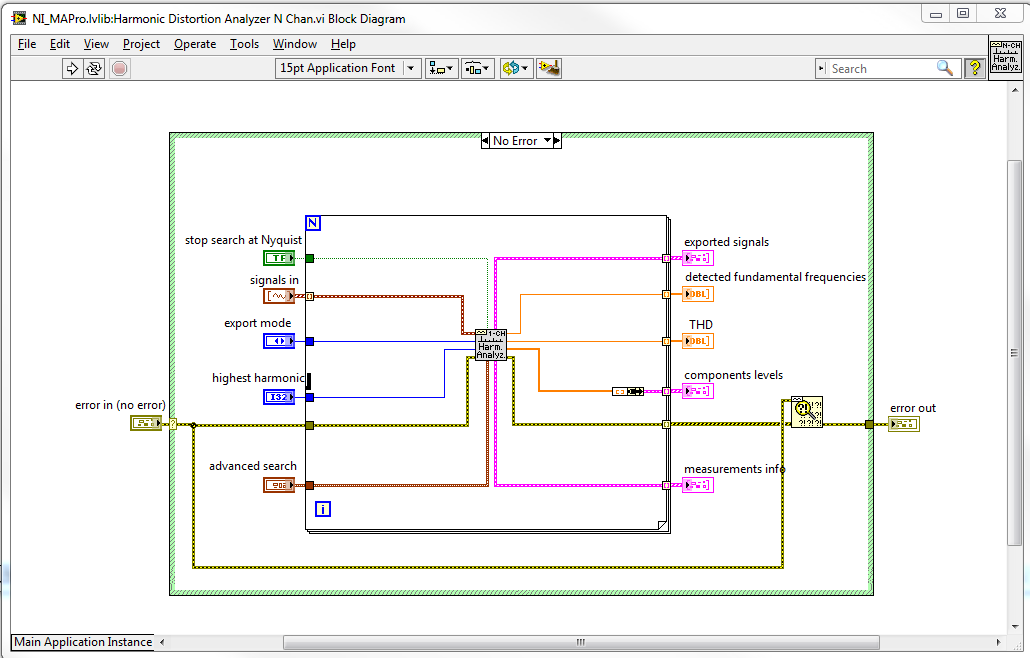
Harmonic distortion Analyzer is a polymorphic VI, this means that if you connect a single signal in and then you get a unique signal, and if you connect a table of signals in out you a table.
The VI I is not polymorphic, but you can easily change to work with multiple signals. If you look at the standard implementation for the harmonic distortion Analyzer N-channel then, he simply called the channel 1 harmonic distortion Analyzer a loop for. So you can easily call my VI in the same way. See attached screenshot:
Best regards
Anders Rohde
Technical sales engineer
National Instruments Denmark
-
determine the angle of a complex signal phase
How can we determine/measure the amplitude and phase angle, separately, signal output complex in AWR in circuit level (schematic) design?
It depends on what you mean by complex 'signal': power, voltage or current? If it is a simulation of harmonic balance, you can use measures Pcomp, Vcomp and Icomp for value complex to a specific harmonic and choose 'Mag', 'Angle' (or "AngleU") as the modifier "complex" for the measure. This can be traced and then compared to what you are scanning. e.g. power, frequency, etc. If this does not answer your question, attach a copy of your project, or at least a photo; So we have some background.
-
How determine the crossover frequency
I'm having a hard time to understand how the high-pass filter determines vs high frequency. What value it measures. ? A change of RGB values or contrast? I see the sharpness of words or blur, but what values determine the amount of blur or sharpening? Is there and the actual frequency being high or is it just a metaphor to compare it to the audio crossover?
No details on the workings of this filter is appreciated.
A few additional explanations:
Audio signals:
frequency = cycles per second
It is the frequency in the time domain.
An arbitrary signal can be represented by a set of harmonic signals (sine, cosine)
In addition, some DC (direct current, non-periodic component).
A typical high-pass filter for audio signals:
The cut-off frequency fc is at the transition between the increase in gain
(low frequencies) and fixed gain 1.0 (high frequency).
frequency reduction (mitigation)
CF 0.01 0.01
CF 0.10 0.1
CF 1,00 0.707
10.0 fc 1.0
100 CF 1.0A typical high-pass filter for digital images:
frequency = cycles per unit of length or (better) cycles per pixel
It is the frequency in the space field.
The highest frequency is 0.5 cycles per pixel (alternation of black and white pixels)
A line of arbitray in a digital image can be represented by a set of harmonic signals
In addition, DC-part.
Each channel that r, G, B is filtered individually, one after the other.
Frequency and gain are as above.A high pass filter applies to mitigation<1 to="" low="" frequency="" signal="">
and removes the DC component entirely. This would result in a black background.
Therefore, the background is extended to R = G = B = 128 (8 bits per channel) or
R = G = B = 0.5 (standard).Edges contain stronger high-frequency components. These are preserved.
http://en.Wikipedia.org/wiki/high-pass_filter
In this doc, we find a simple implementation:
y [0]: = x [0]
for i from 1 to n
y [i]: = a * y [i-1] + a * (x [i] - x [i-1])
return yx [i] are values of R (or G or B) row in column i in the original image
y [i] are values of R (or G or B) on the same line in column I after filtering.
Factor (a) indirectly contains the cutoff frequency.
This example does not yet apply the SHIFT R = G = B = 128.The implementation can be different (filter not recursive instead of recursive, as indicated above,
higher order instead of first order, using a filter kernel 3 * 3 5 * 5 pixels instead of work
in each row independently).I'm not trying to explain how Photoshop! There are so many alternatives.
Cordially - Gernot Hoffmann
-
Problem updating my state machine, using the emg signal
Hello
I have problems with my code. My entry is an EMG signal that I gather from three different electrodes using usb 6008. In the program, I divide the signals and display them in a chart that is unique. What I want now is to read the signal, and if a signal passes a threshold I want an LED lights. This must remain lit until there is another signal that passes the threshold.
To put it simply: "large enough signal--> lamp on--> stay informed--> enough large signal--> lamp--> stay off the coast and then start again."
I tried a few different approaches, but I decided using a state machine. Now, the problem is that when the signal to enter the state machine the program crashes. I think it's because the table that I use to convert the signals does not update when I get my state machine, so the signal stops to come. But how to get around this problem? It is even possible to code what I want?
I have attached the code. All the tips are welcome, I have been struggling with this for some time now.
Thank you
jenmich
The problem is internal while the loop is run until the stop condition is true, but he never does a new Boolean entry. So that it remains for always in the same State. Remove the inner loop and put the shift register on the outer loop instead.
You must also use a daqmx configures the element, and then set the properties of daq. The read.vi can be set to read a number of samples of each iteration.
Also: you can expand the table to index for several items of output. If you want that element number 0, 1, and 2, you have yet to wire the index entries

-
What hearing method uses to determine the overal frequency?
Hello
No one knows which method uses Audition to determine the "global frequency" in the section "analysis of frequency? I need to know how is it calculated?
Thank you very much!
stephaniec9433324 wrote:
Thank you for this! So am I right in thinking "global frequency" is that point which contains the largest amount of energy in a sound sample given frequency?
I don't know why it's called "global" frequency - seems a little strange to me, although you could call it although it is a bit of a mouthful, I'm not sure. But, strictly speaking, what is the frequency of the amplitude higher at this moment on the screen. It isn't really a sign you measure; It's a single FFT 'slice', which raises even more questions, as the sector size determines the resolution and therefore the accuracy of the result in any case.
-
determination of the sampling rate and the frequency waveform data record
Hello
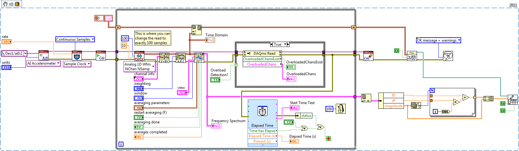
I write a simple program that collect data from a triaxial accelerometer input, convert it to a frequency spectrum, and then save the time domain and the frequency of the waveforms in an external file separated. I don't understand how to set the sampling frequency, however. On the DAQ Assistant, I updated the acquisition mode "Samples continues" and read samples is 2 k, which corresponds to the total number of data points that are collected. How can I program sampling for awhile, it 30 seconds, for example? Wouldn't be better to set up a trigger, as it will continue to collect data up to what I told it to stop?
I also want to save waveform data in a separate file that can be easily seen by other computers that have not installed Labview. I have currently the program put in place to convert a text string of the waveform of the time domain and then save it in a text file or a spreadsheet. It works fine, but I would also like to record the frequency wave, which is a different type of data. How can I do this or is there a better way?
My program is attached. Thanks for your help!
Here's how you can use the shift register to build the table, and also where you can choose to play exactly 100 samples per while the loop iteration.
Brian
-
Using an 53131A, how do I detect the condition of no input signal?
Hello
I use an Agilent 53131 A frequency counter to measure the frequency of the oscillator. I need to be able to use the frequency counter to read the frequency when the oscillator is oscillating and indicate when the oscillator is bad (no signal present on the 53131A of entry). Does anyone have any suggestions on the type of command I should use?
FETCH?
READ?
MEAS?The problem I have is in the trigger. When the oscillator is bad, the counter hangs up because she continues to wait for a trigger that will never come.
Thanks for any help
In fact you have right to the solution yourself. You need to revise your release scheme or you can use the absence of trigger as your indication.
For example: you know that the measure will have x seconds to complete if the signal is present. If you need to determine whether the measure is right here. Simple if you use GPIB-
(1) set the property of VISA TMO to be as long as you wait for the measure.
(2) enable SRQ on operation completes in the meter. (ATTENTION: make sure that no other instrument allows to block Service Requestby the meter setting as low as possible address)
(3) when you send the boot command, you can query the status of the SRQ with the "wait for SRQ.vi" If no signal is present, then the wait fo SRQ will return with a time-out error.
(4) clear the error since you know what caused it and send a clear command (* CLR) at the counter to return to the idle state.
Alternatively, if the signal is present, the meter will trigger SRQ when the measurement is finished and you can then extract the memory reading.
-
Counter counts twice as many edges as it should, but the correct frequency. Why?
Hello world
I use a PCI-6122 (series S, DAQ - STC) and Labview 7.1 on a Windows XP. There are only two counters on this card (0 and Ctr 1 Ctr) and I need to use both of them to count the edges. While testing meters, I am inputing a TTL signal to 10 kHz at the door of each counter, to be used as an external sample clock, and a 20 Hz TTL signal in each counter, to serve as input signal Source. CTR 0 account 40 edges per second, i.e. twice as much as it should, while the Ctr 1 reads the correct number of edges, i.e. 20 edges per second.
The strange thing is that when I switch the connections of the portal and Source for two meters to measure the frequency (or period), two meter to read the correct frequency, i.e. 20 Hz. To the best of my knowledge, the two counters have been reading of the
correct the number of edges a couple of weeks. Also, I have reset the
device several times but it doesn't make a difference. I'm trying to understand why this is happening and how to fix it, but I'm not about to answer each question. Does anyone have any suggestions?Thank you.
After many tests on mine, and talked with an engineer of NOR and repeat tests by telephone, it seems that there is something wrong with the meter (a) on the Board of Directors. I sent it for repair (luckily it was still under warranty
.) -
Synthetesis of frequencies with filtered signals (Convolution)
Hello
I am a new user of DIAdem and I analysis of the signal.
To deal with my purchases, I use several tools alreaydy implement in DIAdem. But I want to do a convolution of the signal number to make a spectrum of synthesis.
In fact, I want to filter several frequencies on a signal and put them in a same spectrum, think a convolution of each of the signals.
How can I do that with DIAdem?
Best regards
Pascal GRAIGNIC
Hi Pascal,.
I'm no expert in acoustic analysis, but it seems to me that you could simply add together the resulting chains of each single frequency filter digital function of the results of the ANALYSES. The result of the calculation of digital filter in tiara is a curve of time series that contains only the frequency components with a size proportional to the contribution of the relative amplitude of frequency of such component (s) to the curve of time series (complete) original. There is a function of multichannel totaling in the palette of the ANALYSIS of "basic mathematics".
Brad Turpin
Tiara Product Support Engineer
National Instruments -
How can I make a feature to create a table of values of variable size, which I can take the median?
I am new to LabVIEW all this, I know it's a simple enough question, but:
I create a montage where we have two pressure - low pressure and high pressure sensor transducers. The problem is there is noise in the signal I want to reduce - I don't have the full version of LabVIEW (base only) so I can't use the convenient median PtbyPt.vi to reduce the noise, but I wrote something that I thought would work (attached). The question is twofold:
(1) I don't get pressure readings when I know that the system is empty.
(2) the change in pressure is too slow for the application in which it is used - for example atmospheric pressure reading empty takes minutes when it should take seconds. I think I could solve this problem with a business structure that analyzes the table to see if the pressure changes vary more than a certain amount. If so, do not take the median.
Any help would be greatly appreciated!
Just make your own way to pt by pt. I did one here
-
How to find the ratio between the two frequencies in the fft
Hi, I'm Jean,
I need to find the ratio of the frequencies of 1st and 2nd graph fft.
Already, I received information of this site only. Mr. Alten helped me.
Now, I have to continue the same problem and need to find the ratio of the frequencies.
Please someone help me guys...
I will attach my vi file and the text file.
John,
Should you report the frequencies or the report of the amplitudes of the components at these frequencies?
The Information.vi of your multiple for the Signal Processing, extract > range of measures of waveform should do what you want.
The frequency resolution is not very good because you have cycles relatively little waveforms (2 ~ for the lower frequency). I added a few zeros to improve resolution, even if a larger sample of data would be better.
Lynn
-
find the fundamental frequency & treatment
Hello
I am in an interesting situation, I am processing a signal (Labview8.2) looking for a fundamental frequency using the Analyzer SINDH and harmonic distortion Analyzer, but I need to build again the signal using only the basic and some of its harmonics frequency signal,
Suppose that some time, I need to add up to 5 harmonics built the signal as well as the fundamental frequency, and some time the number of harmonics must make six or another value.
in this part, I'm hard to find, can someone help me? There is a VI that can directly do the job?
Hello!
Looks like all you need is the filtering.
Kind regards.
-
How to find the sampling frequency to read the measurement file
Hello
I would like to find/extract the sampling frequency of a .lvm file.
Right now I am using the VI 'read file of measurement' and my data charge fine and all, but I need the frequency of sampling for certain calculations.
I know the header of the file .lvm that the sampling frequency is 1613Hz, but I want to get this automatic information from the open file .lvm.
Tried to find an express vi that could give me the answer, but I could not find a

I'm sorry if this question already answered, but I could not just to find the answer.
I hope you understand what I'm doing!
Thank you
Kind regards
Tommy
The timing is part of the production of signals information. Never use the functions of the Express, but you can use DDT to and convert to one of the data types of waveform. Waveform components then turns the dt.
Maybe you are looking for
-
What can I do if an app downloaded from app store warms my phone and drains my battery?
Hello I downloaded an app on the app store and it warms my phone. I want to use it, but it is almost impossible to communicate with application developers. How can I ask Apple to check the application and communicate with them? I really want to use t
-
Tecra M4 - lines of vertical black pixel on the screen
Hello This morning I turned on my laptop and suddenly I have vertical black pixellines more my whole screen.There's a line that works normally, who is black, a job, a black man,... and this all over the screen.In this same way read something is very
-
Hello I've been using G500s for 2 years. Is having some problems of charging since last 1. After using for a while or playing a game, his forehead two LEDs (ON / OFF status and battery LED) began flashing and portable load order. After a while he sta
-
With the help of IVI driver for delay in the MSO6104A of reading
Hello I have the IVI driver NOR for the scope of the MSO6104A. The driver is functional, and I managed to use it. My scope has a function of delay between two different channels. But, how to read delay help scope step IVI measurement? Is there anothe
-
How can I change a click to access to the files on my desktop it please?
I changed mine because of old arthriticy hands and you want to help a friend, but lost unstructions Windows tips and tricks