Develop the VI for acquisition of data that is actually disconnected from the PC
Hello
Data acquisition for which I develop a VI is in fact used for certain jobs, so it is not connected to the PC.
Is it possible to 'activate' the device in order to use their resources for development purposes.
Thanks in advance
I'm not completely sure that it will work with just the DAQmx Runtime. But after selecting DAQmx simulated device, click Finish and see what appears in the insuing dialog box.
Tags: NI Software
Similar Questions
-
Why is that every time I open an application that my phone disconnects from the wifi
Everytime I open an application that my phone disconnects from the wifi.
Here's a tip for the user on the problems of Wi - Fi. Suggest from the top and bottom. Maybe one of them will help you.
(1) perform a forced reboot: hold the Home and Sleep/Wake buttons simultaneously for about 15-20 seconds, until the Apple logo appears. Leave the device to reboot.
(2) resetting the network settings: settings > general > reset > reset network settings. Join the network again.
(3) reboot router/Modem: unplug power for 2 minutes and reconnect. Update the Firmware on the router (support Web site of the manufacturer for a new FW check). Also try different bands (2.4 GHz and 5 GHz) and different bandwidths (recommended for 2.4 to 20 MHz bandwidth).
(4) change of Google DNS: settings > Wi - Fi > click the network, delete all the numbers under DNS and enter 8.8.8.8 or otherwise 8.8.4.4
(5) disable the prioritization of device on the router if this feature is available. Also turn off all apps to VPN and retest the Wi - Fi.
(6) determine if other wireless network devices work well (other iOS devices, Mac, PC).
(7) try the device on another network, i.e., neighbors, the public coffee house, etc.
(8) backup and restore the device using iTunes (ask for more details if you wish).
https://support.Apple.com/en-us/HT201252
(9) go to the Apple Store for the evaluation of the material.
-
Operating system: Windows XP
Hardware: PCI 6259
Terminals used: PFI0 and PFI2
Counters used: Ctr0 and Ctr1
IM developing an application for the acquisition of data where timed loop synchronization source comes from my PFI2 (using the string A of an encoder). IM basically trying to acquire data based on the number of ticks from my encoder. For the synchronization source, I use counter 1 to capture the rising edge and have the loop time-acquisition of data. At the same time, Im using the counter 0 to count the number of rising edges so I know exactly in what tick data was acquired. PFI0 and PFI2 are connect to channel A of the encoder.
Questions:
Timed loop acquires data at each tick, because when I discover the data (text) file is missing count of my encoder value. Is it because there is a limitation on the Windows operating system? I used a noculars to measure the frequency at the maximum rotation of the channel encoder and 6,757 kHz. All solutions?
Also, is there anyway I can route the source channel internally an encoder to generate synchronization source instead of using another counter? I have attached my VI.
Hello
All the samples that you acquire will be read by LabVIEW in a sequential manner. Figure 4-21 on the M-series on page 80 (4-34) shows that you will acquire all the samples you request all channels that you enjoy in sequentially.
-
Difference between DAQ and DAQmx for acquisition of data PCI 6534
Hello
I use the PCI DAQ 6534 card for my digital I/o transfer. I am beginner in the labview.
I want to store the data coming in memory and the reading of the data at the level of the trigger.
I have seen the examples in the labview. Some have used DAQmx and DAQmx read write that screws and some have used the confg DIO port and all...
So I want to know the difference between these two. For my application that I use?
Hey Bo,
First of all, I would recommend that you discover the NI 6533/6534 for NOR-DAQmx help. You may be able to find some of your answers in this help document. Now for what you try to do in your application, it looks like you are only buying data. If this is the case, with the 6534, the device acquires data in memory shipped as soon as the DAQmx series start task VI, as long as you don't start hardware triggers have in place. If you have a trigger of starting material, then will make the purchase of the aircraft after the DAQmx start task VI and only after you receive this material trigger. If you call not the DAQmx Read VI, then the data will be stored in the memory board for you, as the driver manages this data in the on-board memory storage, until reading DAQmx VI is called, which at that time, data is transferred to the Board of Directors in the memory of the computer. Once you get it in the computer's memory, you can do whatever you want with these data, as this graph or treat. If you look at the sample programs (which have been mentioned on how to find those in a previous post), you can find an example that little shows you how it works. One of the examples that you can check is called reading Dig Port-Ext Clk.VI. In this example, it sets up to read a finite number of samples and then starts the task. If you set a breakpoint on the line of the error after the VI begin, the data will be acquired in the amount of on-board memory. Then when you cancel the break of the VI, data will be extracted from the amount memory embedded in the memory system with the reading VI DAQmx. Again, the pilot takes care to put the data in the memory board for you once you start the task.
I hope this helps. Please let us know if you have any questions or concerns about this issue. Also, certainly, discover and try to run all the programs related to the 6534 examples so that you can learn how the equipment works and how to use features to do what you want your program to do. Also, be sure to read through the help on the 6534, as well as the help of VI documentation to learn what makes each function. Thank you and have a nice day.
Kind regards
DJ L.
-
Sampling frequency for two different routes for acquisition of data USB-6009
Hello
I use a box USB-6009 and incorporating the "daq assistant" to change the sampling frequency. I'm trying to find a way to set the sampling frequency to two unique values for the two separate channels. I tried implementing two assistants daq and different for each channel sampling frequency setting, although it does not work. Is it possible to set the sampling frequency for all channels, and then reduce the rate for another channel - or an alternative? I would be recognizing any input on this matter, thank you!
-Anthony
All tasks on a DAQ card using the sample clock should use the same clock. Therefore, you cannot have two tasks on the same sample of DAQ card at different rates.
Alternatives would be:
1. to combine all channels in a single task and to accept additional data
2 get an additional DAQ card to use at the same time
-
Link a JSF table to a list of data that does not come from a database
Extract data from a database, I can just jDev Wizard allows you to 'Create EJB from the table' and link the EJB to a table of JSF in a NamedQuery.
However, in this case I am recovering from a list of data from an existing API or a Web service.
Someone at - it a good example of the best way to do it?Hi Owen,.
You mean that you do not use anything from the ADF (RC components or controls data)?
Extract data from a database, I can just jDev Wizard allows you to 'Create EJB from the table' and link the EJB to a table of JSF in a NamedQuery.
The principle must be the same, regardless of how you get the data you return from the method (NamedQuery or something else).
Your example seems ok, so 4) is clear to you (I don't know how you lie the DataTable to the method, never used).Pedja
-
Acquisition of data and filtering on FPGA
Hi all
I have trouble to design a FPGA program for acquisition of data and filtering.
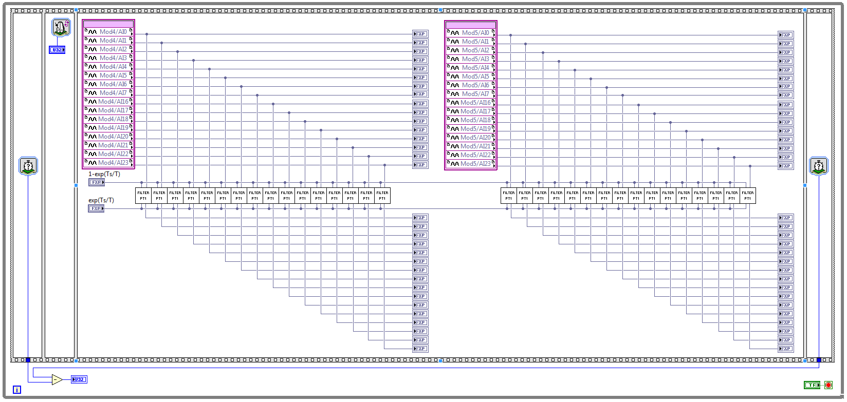
I have two NOR 9205 modules configured to work in terminal mode of DIFF, i.e. There are 32 entries this program must read every Ts seconds. (Ts is the time discretization, i.e. during the period of loop)
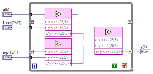
With respect to the digital filter, I implemented a possible simple filter with transfer function G (s) = 1 /(1+sT), which is part of the field of discrete-time equal to y (k) = a * u (k - 1) + b * y (k-1), where u is the original signal, and there is filtered signal. The coefficients a and b are equal to: a = 1-exp(-Ts/T), b = exp(-Ts/T), and T is the time constant of the filter (usually T > 5 * Ts).
The implementation of main program for the acquisition of data and filtering are:
This application is for the digital filter:
However, the problem is that this program cannot take the FPGA resources on cRIO-9114, and Yes, I tried to define the criteria of compilation for the area. I also tried to implement the multipliers in digital filter as lut and DSP, unfortunately without a bit of luck.
Because I don't have that much experience in programming of FPGA, someone has any suggestions how to improve this code to adapt existing FPGA resources?
Best regards
Marko.
Hey Norbert_B,
I managed to solve the problem. First, I changed the reentrancy of Preallocated incoming execution clone to not reentrant execution. As no reentrant VIs have States, I had to use the node of the feedback to the main VI to get u(k-1) and y(k-1). Another important thing is to choose Ignore FPGA reset method in the node of the properties of FPGA implementationfeedback, since in this case, the feedback node uses less resources.
Here is the new main program VI:
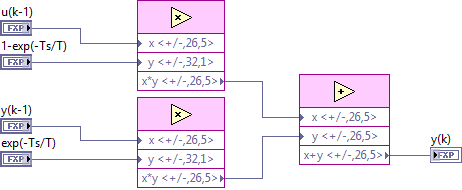
And here's the 'filter' VI:
Thanks for the help!
Best regards
Marko.
-
Wireless router is disconnected from the PC (s) during the use of Firefox 37.0.1
This problem occurred for the last 2 weeks whenever I use Firefox on each of the 2 PC's I use it every day. The problem may occur a few minutes after the start of Firefox, or it may be hours of continuous use before the connection is lost. It's okay if I'm in Firefox by itself or have the background applications running, but without a doubt requires Firefox runs before I see a problem.
Configuration: WIN 8.1 and VISTA 64. the two latest updates.
LAN: cable modem and Belkin wireless router; together with the latest firmware.
Firefox v37.0.1 without add-ins or modules. Start page is 'empty '.Symptoms:
Status bar Windows shows that I'm disconnected from the router.
Router and the modem status LED shows that I am connected to the internet. Same thing for the VICTORY of the network status app. It shows no connection to router.The problem can be temporarily fixed by power cycling the router. Or, in the meantime just a random delay the connection may (or may not) be restored on its own.
I also use a standalone PC application that streams the text given in short bursts and runs all day (no video or music... just short lines of text) with no problems until I launch Firefox in the background. Then he can go a few hours before the connection to the router is lost. I also often watch videos on my Tablet without the router problems. While typing in this issue on a PC I was disconnected from my router. I'm hoping to get some suggestions as to what to inspect or modify. Thank you!
Fred, I had to leave the House early this morning and had no time to dig a cable long enough to reach my modem to try your suggestion. But, what I did was half of your suggestion. I pushed the reset bit recessed on the modem and left the House around 08:30 with Firefox running on both computers. Seven hours later everything is normal. No router disconnects and I gave a very good workout system.
I have also now initial notice that connects to the web sites are faster.
It is obviously a logical explanation for what was going on, but to an outside observer (), I see absolutely no logical link to the 'solution' for the rest of the universe. I won't lose sleep on. And I'm going to ask you more specifically when the next puzzle problem occurs! Thank you, Fred!
-
Computer disconnects from the local network after a while
Hello
the place I work has a local network with nearly 20 computers.
One of them is used only to receive some PDF files from the scanner and there our database (PostgreSQL).The problem is that, after some time we can not access it via Explorer by typing '\\server' on the address bar, but the connection to the PostgreSQL Bank will continue to operate.
I have already disabled the drive for energy savings computer network mode.
What can happen and what can do?
Thanks in advance,
Felipe SousaHi Felipe,.
Thanks for posting your query on the Microsoft Community.
According to the description, I understand that your computer disconnects from the local network.
I suggest you post your query on the TechNet forums , because we have experts working on this type of questions and for you help the better.
Check out the link:
https://social.technet.Microsoft.com/forums/Windows/en-us/home?category=w7itpro
Hope this information helps. Please let us know if you need any other help with Windows in the future. We will be happy to help you.
-
Anyone else is disconnected from the creative cloud after signing?
For some reason I keep to be disconnected from my creative cloud account. Normally, I'm signed in automatically. But today the creative Cloud application asks to connect you. And then after a few minutes, I get kicked out and have to log in again.
Stem
If you have windows
1: open the Task Manager and end Adobe all processes. You can find the process as AAMupdater, AAMupdater notify, Adobe crash the daemon process.
2. now navigate to c: / / Users/username/appdata/local/adobe/OOBE and rename it OOBEold. and aamupdator to aamupdator.old
3: then run creative cloud, login and click on the applications tab.
-
We send 5v data acquisition using a voltage generator. Hook us it up to a voltmeter and see 5V. When connect us the generator voltage to a valve "normally open" parker, the voltmeter indicates .14V. It seems that when we connect the two sons of the valve for the voltage generator, the son act as pattern. We want to control the voltage flowing to tap through Labview. We checked the wires to the valve and they work very well, because if we send a constant 5V since the acquisition of data and put ashore, she, the voltmeter indicates 5V. Someone knows why the son act as pattern and low blood to .14V?
nsatpute wrote:
Our data acquisition is NI USB-6259. The valve requires only a 5V max and our DAQ provides up to 5V. However, after connecting the valve to the acquisition of data, the grave tension to almost 0. We start from the principle that the son somehow act as the reason, but we are not sure if this is the case.
The question here is not how much voltage the valve wants, it's the current needs of the valve. The 6259 can put only 5mA via an analog output. Your very likely tap needs much more than that. If you need to add in an amplifier circuit that can supply more current to operate your faucet.
-
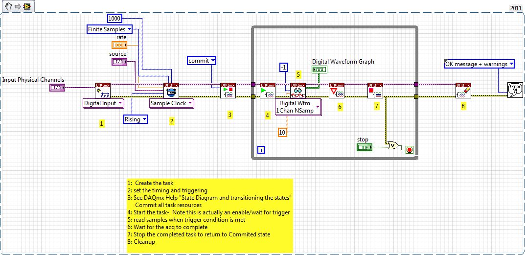
Restarting a task for the acquisition of data inside a For loop
Hello
I need iterate through my acquisition of data. Currently, I'm doing this through the creation, implementation and tasks for the acquisition of data inside a loop For which is iterated according to the needs of compensation. Unfortunately, the creation of these DAQ tasks slow down my code.
I would like to be able to create the tasks outside the loop, pass them in and revive the tasks at the beginning of each iteration. Is there an easy way to do this?
Otherwise, is there a way to make the standard DAQmx digital startup trigger trigger several times (so that it starts each pulse data acquisition in a long pulse rather than just the first pulse train)?
Thank you!
-Evan
I whent before and created this example for you (and many others.)
-
Hi all... I learn LabVIEW since few days.i want to acquire a signal of pc6251 of acquisition of data and perform fft it can u people please help me? Thanks in advance
If you do only use LabVIEW for a few days, you should get familiar with it first by looking at some of the resources available here. After that, you can watch heredata acquisition.
After reviewing these documents, you can post back with any specific questions.
-
Calendar for the acquisition of data on the USB-6212
I am putting together a sound teaching laboratory. The basic idea is to send a pulse signal that powers a speaker, and then the acoustic signal travels down a waveguide where it is measured with a microphone and sent to a data acquisition. One of the important things here is that it is possible to measure the time of propagation of sound waves, so I need for data collection to occur at a time determined with reference to the sound output pulse. I tried with a sound card, but there are number of milliseconds of random jitter between the writing and the reading of the sound card.
So, I was watching the USB-6212. On paper it seems ideal: 2 outputs and lots of inputs. What I understand, it is possible to trigger analog outputs and data entered so that there is no jitter synchronization between them. The only question is this: I was thinking about using 2 analog inputs: a reference which collects through a microphone/speaker system to serve a normalization to the second chain that collects through waveguide (see diagram). The thing is that I need the "timing" on the 2 analog to be consistent and a jitter free so that it is possible to compare the phase of the signals that I collect. This will be possible using this data acquisition system, given that the ADC is multiplexed between the channels? There will be a delay between channels 2 and if so it will be known and deterministic?
Thanks for your help...
Ben
Hi Ben,
Cool application! To answer your question-Yes, there is a delay, and it is deterministic. Something to note about the 6212 is that your rate of multiplexing will be determined by the clock to convert. The clock to convert will operate at the faster pace of the device more 10us *. In the case of the 6212, with Max sampling rate of 400kS/s (aggregation), your pulse will produce each ((1/400,000) 12.5us + 10).
* 12.5us converts to 80 kHz, so at that point there, convert clock it simply runs at 1 /(aggregate rate). So to sum this up:
From 0 to 80 kHz: there is a lag multiplexing 12.5us
From 80 to 400: there is a shift of /(aggregate rate) 1
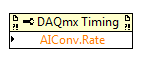
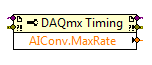
In addition, you can also set this rate through the DAQmx driver. "You can just use a property DAQmx Timing node' more' converted ' rate (or rate Maximum to determine the max).
If it's a problem, I advise to use a device with simultaneous sampling - let me know if you have any other questions. Take care!
-
I have a PCI 6519 data acquisition card. I want to install it on the PC and use it outputs to control a robot. I have problems with the connections to the terminal block which is attached to the cable.
What type of connections I do for the acquisition of data PCI 619 card pins? What I have to give it to the ground and the CCV on the pins of the connector myself? What should be the value of the SCR I need to give to the PIN?

Maybe you are looking for
-
Pavilion dv6tse - 3100: laptop screen turns sometimes and sometimes does not work
When I turn on my laptop, there is a chance that the monitor does not light. What to do when this happens is I turn it works again and again until the screen lights up finally. When it lights up, it works very well and stays on until I turn it off an
-
My ID Windows Live ID gets me from my Money Plus program. I have reset my WILID; still no go. I downloaded and installed Money sunset; still not bring. Tried to create a Hotmail account with the new Windows Live ID; don't agree. Is there no solution
-
Impossible to uninstall a free trial version of nero
I'm unable to remove or uninstall a free trial version of nero 11. The trial has expired, but I cannot uninstall the program from my computer. After an hour of uninstall, I get a warning that the installation failed. Help!
-
Problem update the eponymic information from a mixed CD using Windows Media Player.
(Last?) version of media player, the I installed (11.0.5721.5280) does not seem to have the same functionality as the previous version I was using (10.00.00.4081) when it comes during the extraction of information albumn and song from the internet fo
-
Cannot open BKF files on disk external usb2 (G) __a Vista Home premium
Files BKF (backup utility) comes from the previous windows xp computer