differential measurement high voltage
Not sure if this is the best place, but here goes.
We are trying to measure a voltage differential across a shunt in offset voltage, which is then further +/-10V over data acquisition cards measure. Here's a representative diagram of our circuit:
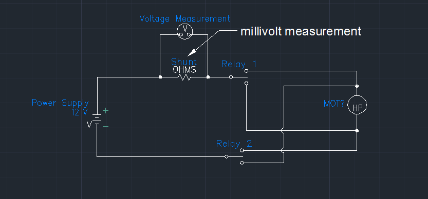
We must also measure 24 of these shunts while we move the motor one way or the other. That in one case the offset voltage is near current of 12 volts (rank 9-16Vcc) that eliminates all the cards of the cDAQ and it looks like the PXI series too. We currently use one SCXI-1104 researcher but a USB port on a laptop for this measure. The SCXI-1104 has a voltage range of + / 60V and I was unable to find anything close to that in the product offerings of NOR. The reason why this is going to be a problem for us is that large corporation, we are forced to move to windows 7-64 bit and SCXI hardware are not supported for this operating system.
I am open to any suggestions that others may have to help us fix this problem.
Thank you
Bill Lane
We ended up finding some amplifiers that have been specifically designed for the high pressure shunts. Do a search on digikey for amplifier of high-side current shunt and you should be able to find something. These will turn the measure into a single measure is over voltage.
Tags: NI Hardware
Similar Questions
-
How to measure high voltage (60-70 v) and current (75-80 a) using a DAQ PCI or USB DAQ
Hello
I work with a system that works on about 5kW. The output of the system voltage can go maximum up to 60-70 v and thus the corresponding current around 75-80 a. I have 10 these systems that I want to read one by one continuously for long periods.
I am designing the automated system best suited for this and looking for the best material that would be appropriate for this purpose. Looking for options, I found that an SCC - A10 attenuator may be used to get the tension down by a factor of 10. But I'm confused, if the high current will pose a problem and also how to measure this high current.
I need to measure the voltage and current at the same time. Please suggest what would be the most appropriate fitting for the same (preferably PCI or USB)
The hope of a quick response. Thanks and greetings
Reena Sharma
Facilitated learning
Reena says:
Hi all
There is good news that the idea of using a compact data acquisition has been accepted by the authorities of the society. I'll be very grateful, if you could suggest me with some hardware modules suitable for my application and how I can use them best.
Thank you very much
Reena
I was able to make a few suggestions, but do not have the time to understand your needs and the forums are not the best solution.
Your Local OR representitive actully gets paid to do this kind of thing. a google search suggests THAT LME is in Pasadena. Zack Collins would be the contact rep
-
Measurement of differential tension for voltage range 0-20 V
I'm trying to understand the best way to measure the internal tensions in a pile of electrolyser containing 10 cells. Voltage range is 0 - 20V, with each measure 0 - 2V voltage differential. I know that each module on a NOR-DAQ (6218, 6210, 6009, etc.) can not see voltages greater than 10V. If I use the AISense or the second Chamber of the ground to the high tension of the first 5 cells (~ 10V), I will damage the Board or which will allow me to reach the upper limit of 20V of the system. In addition, I need to be able to measure the voltages at the same time.
If there is a piece like hardware or the Commission on this topic, please let me know. I write on the multifunction DAQ card because it is the material that I am familiar(-ish) with and that's what we have at home right now.
Hi sbrawn,
I recommend reading the high voltage and DevZone isolation measures.
If you are looking for a DAQ hardware that has a range of over 10 V voltage, I recommend searching the catalog of products here.
-
Hello people,
I've read several documents on the site OR about the premium over common measures of mode and I think I understand, but I'm looking for confirmation through two examples (please).
Both examples assume a data acquisition card OR with +/-10V inputs and a maximum operating voltage of + / 11V (e.g. PCI-6052 with programmable gain 0.5).
Example 1: Suppose a DC voltage with two resistors divider and a differential input on the daq card configuration. First resistance = 4 Ohms connected to 100VDC, second resistance = 96 - grounded (0) Ohms. This results in a decline of 4VDC to the terminals of the first resistance. However, I believe that the differential voltage of 4VDC may be connected directly to the daq card because the absolute voltage (i.e. common mode?) is in fact 96VDC to 100VDC which is outside the "working range' of + / 11V for the card. This conclusion is correct?
Example 2: Suppose a differential measure between two AC signals and a differential input on the daq card configuration. First report = 25v@0deg, second signal = 10v@180deg. Some documents on the Web site of NOR, I gathered that the common mode voltage is the average of the vector representation of the input signals. In this case, it would be (25v@0deg + 10v@180deg) / 2 = 7.5v@0deg. I think that this signal can be directly connected to the daq card because one of the signals (25v@0deg) is outside the range of the card work (even if the result "means vectors" is within the scope of the map daq. This conclusion is correct?
Thanks in advance for any help,
chassan
Chassan,
You're right both of your examples. Is the best way to look at that is that even if you take a measure differential the maximum voltage you can submit a single channel to the + / 11V to the 6052E. Hope this clears things up a little bit.
-
With differential measurement noise problems
Hey everybody.
I use an NI USB-6211, LABView 2011 and Win7.
I'm trying to measure a voltage through a resistor using differential mode. But unfortunately im getting a lot of noise (on + - 25%).
The voltage source I use is variable and can go up to 600V. With my diet I am essentially heat a metal plate.
A parallel voltage divider is used to reduce the voltage by one hundredth (1 MOhm and 10 kOhm).
Two wires attached to the lower resistance then go directly into analog input 0 + 8 of data acquisition.
So if I'm trained 600V to the plate, data acquisition should get about 6V... and that's what I measure with my voltmeter attached to the acquisition of data input pins.
I also tried these resistances of POLARIZATION and connected the + and - leads to the analogous to the ground like a resistance I used 10 k, 100 k and 1 MOhm and 2 MOhm and
continue to receive a bad signal.
Two sketches of the wire as a signal (100V, supposed to measure 1V, no CORRECTION) are attached to the post.
Concerning
EDIT: I forgot to write that I even tried an another NI DAQ and still get this noise problem.
Also, I measured the voltage source signal using an oscilloscope and I see that noise. But the differential mode isn't supposed to
reduce noise to a minimum?
Hey everybody,
come to understand that the voltage divider resistors are medium to high and they were the main reason for the noise
problem.
Before I used 1 MOhm and 10 kOhm, now I use 100 ohm and 100 kOhm and with a median filter in this regard, it works very well!
But still, if I use the resistance of these BIASES they do not change.
Concerning
-
Differential measurement across the ground of the card NOR referenced output.
Hello guys,.
I have a question, our pure curiosity.
I use map of USB6212 to apply a sinusoidal signal of 10V to a game to the top, then measure the tension between charges.
I'm attching here a simple diagram showing the system. The implementation can be modeled as a combination of RC - r series
Note that I'm also measure voltage R2 in differential mode. Now that I am after is exact phase of monitoring between the two voltages (according to the RC and the R2).
My question: is the correct diagram? I mean - is it OK to measure the voltage across R2 in differential mode with attached as such polarization resistors?
It is one of the lines through R2 is already at AOGND. And AIGND and AOGNd are already connected inside the card, it will be then introduced errors?
or does not at all?
Thanks guys, will be grateful for a quick solution.
You can do this but the differential mode does not have much. Your signal source is single ended. The voltage at the terminals of R1 - C can be measured in different ways. It really is meaningless to measure the voltage across R2 differently because one end is connected to the Earth. Polarization resistance, Rb, are not necessary in this case because the low enough impedance DC railways exist at all entrances.
What I would do, is make two measures ended up alone. AO1 measured on a single channel (AI0). Measure the R1 - R2 junction on the other channel (AI1). Then the input voltage is AI0, the voltage at the terminals of R1 - C is AI0 - AI1, and the current is AI1/R2. You will need to enjoy fast enough that the time between the different measures does not contribute too much to the phase error. It depends on your frequency of signal and eligible errors. Look at the charts of a waiting time to page 2 of the NI USB - 620 x specifications for more information on how to compromise between the speed, accuracy and multichannel source on measures resistance.
Lynn
-
measurement of voltage longer distant
Hello Forum,
I have a very important question. I want to measure the voltage difference between two locations on a surface which are location 100 meters. So I'm going to use long cables. The sensors are reference electrodes. What connection mode will be the best for this measure? Single Ended (one of the references in the ground), which is the difference?
Any ideas will be greatly appreciated and kudo'ed

Hello
I'm not familiar with the reference electrodes, but I think I'd go with a differential configuration for your application because of the length of the cable (I'm guessing 2x50m or more?). Here is a tutorial about voltage measures: http://zone.ni.com/devzone/cda/tut/p/id/7113 I hope that you will find some ideas on it.
The problem is that any current through long threads will cause a voltage drop noticeable across the cable leading to the precision of the measurements. It is further complicated by different loops of Earth created between the ground potentials.
Best regards
Matej
-
Measure the voltage and the temperature at the same time with a single card PCI 6014 DAQ?
Hello guys,.
I'm doing a charger measuring the voltage of the battery, the charge current and the temperature of the battery using a 6014 cardboard...
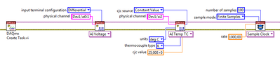
I want to use my PCI6014 DAQ card to measure 2-channel analog voltage input and 1 temperature Channel Analog input using thermocouple type k measurement of voltage or temperature isolation is OK, but I can't understand how to measure the voltage and the temperature at the same time... I want to use input differential...
Thank you in advance, all the tips
YSL
Create a task and add channels to the task, as follows:
Christian
-
Need help with ordering high voltage
Hello
NI PCIe-6341 card is already installed. And I want to order a power supply voltage (CZE1000R) to generate the high voltage (DC). The goal is to fully control the high voltage. For example, the voltage can chang from zero to 30 kV in 5 or 10 seconds and be stable to 30 kV to 30 minutes and then go down smoothly at 20 kV in 5 minutes and finally back to zero. Could someone help me with this task? Thank you.
Hi, apok,
I used the 'panels-test' on 'measurement and automation explorer. And I see signals on an oscilloscope.
Thank your for your help.
But when I try to test the "tension cntrl.vi" it has not worked.
On the manual, he said:
"
Programming with external voltage:
Disconnect between TB1-2 and TB1 - 3 riders. Connect signal 0 - 10V between TB1-3 and TB1-6 (common)".
This means that I need to plug TB1 - 3 and TB1 - 6 and out of the acronym to TB1-3?
-
high voltage damage your iphone 6s?
high voltage damage your iphone 6s? what is the effect
It's an electronic device, then Yes, the high voltage can do all sorts of unpredictable effects for an iPhone or any other electronic device. Cannot specify extent of the damage, but would probably be all that could be fried.
See you soon,.
GB
-
Error in boot sequence because of the high voltage via USB port
Hello
I have connected a powerable Seagate hard drive external via USB of my touchsmart PC and powered the drive using an adapter instead of the supplied 5V 9V (was a mistake). The computer immediately stop (abnormally) and now when it starts it does not recognize the boot drive. The back will ask for the boot drive. My C drive has been fried due to higher voltage? (9 v or 5 V). Is it possible to fix this error, or if not at least can I recover data from the hard drive?
Thank you
Hello
You could try to remove the hard drive and then place it in an external case 3.5 '' USB and then try it on another PC. This type of adapter may also be used to test the drive on another PC.
-
Measure the voltage and the temperature simultaneously with PCI-6281
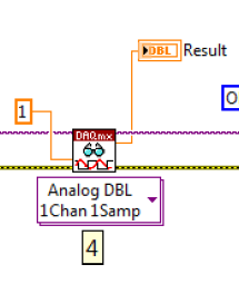
Measure the voltage and the temperature at the same time at the same time. However, when I put the voltage and temperature in a loop, the acquisition of voltage is significantly delayed. When I put the voltage and temperature in two different loop, none of them works. There is an example in aid of Labview as shown. This structure works fairly quickly? In addition, how a volgate get and temperature Analog DBL 1Chan 1Samp? I check the exported excel, the first column is 0, 1 the second column contains the value of the voltage, temperature value. I wonder how can I get these two values for each scan.
,
Assuming that the DAQ cards can handle it, you can set an analog trigger for the channel of the tension. Then you just X samples to get your 100us data value. Keep the last sample.
-
Measure the voltage of strain gauge
I have connected my 9237 to a 9945. I use a 350 ohm strain gauge. I have the voltage set to 2, 5V Max is there a way to measure physically to be sure that it is 2.5V? Also, in my vi I use a DAQmx create function of the channel. I want to add another channel for this but can't see how to do it.
Thank you
HS
Hi, Harry, it's Paul with engineering Applications to the OR.
My first question is why you are wanting to physically measure the voltage?
If you are wondering how that tension may vary, it is limited by the maximum capacity of 150mW of your device, as explained here: http://digital.ni.com/public.nsf/allkb/7CBC67482CC9FB318625758C0048FF73?OpenDocument
If you want to continue to measure externally, you have a few options. You can use another DAQ hardware to measure the voltage, or you can use another external device, like a digital multimeter.
If you want to see in the excitement that is actually supplied LabVIEW code, you can use the node property DAQmx 'Value of real excitement'.
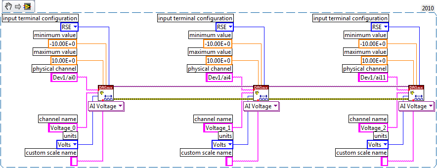
As far as playback of multiple channels, theres two ways you can go about it. If your channels are sequential and all have the same settings, then you can change your name of the physical channel to something like 'Dev1/ai0' to ' Dev1 / ai0:3: to specify the first 4 channels.» Alternatively, if you wanted to select non sequential channels, you can chain create channel set tasks, as long as they are of the same type of task (AI voltage, etc.) and the same device, as shown below.
Let us know if you have any other questions.
Kind regards
Paul
-
Complete noob - would like to measure the voltage to manual start and stop
Hello
As the topic says I'm a complete noob when it comes to programming OR.
I'm looking for someone to point me in the right direction
Installation program:
Windows8 office
Visual Studio 2013
NI 6255 PCI data acquisition card
Block connection OR SCB-68
What I want to do:
I want to write a console application to measure the voltage on the signal ai16
-I want to be able to start and stop the application manually
-I want to be able to pressure measured in a CSV output.
Where I am:
I compiled and ran the example "NOR-DAQ\Examples\DAQmx ANSI C\Analog In\Measure voltage.
It is said that I have "collected" samples but I don't know what that means, as I do not see an output file...
What I don't understand:
Samples - I do not understand cela or know even where to start
How can output file - I get the file to save the collected data.
Thanks in advance
Chad
Hi Arron
Thanks for the link, unfortunately, it has not helped because the instructions were for Visual Basic and C++ not. It was my fault for not putting the language of prog that I need help in my original post.
However, I started to find help on this link: http://www.ni.com/tutorial/5409/en/
-With the help of NOR-DAQmx in text based programming environments
-
Measurement of voltage detection failure
Hello everyone
I am a new user of Labview and I try to measure a voltage but is facing difficulties.
I use:
Worm - Labview 8.0 on Windows XP
-Based electric circuit with a voltage generator and resistor for voltage
-A connection block 68 CBS
-A NI PXI 1042 chassis
But Labview seems unable to detect my acquisition circuit, I tried to use the DAQ assistant > analog input > tension in my new VI, but it has not detected any device.
I miss any point?
Any help would be welcome, if my explanations are not clear enough, you can ask me some questions.
Thank you for reading my post.
DAQ Assistant materials should not be your FPGA. Looking at different sets of drivers.
I expect to see the device in your PXI system, if Max.
To work with this device, you do not add the DAQmx code in your code and go from there. You will never get a reading. Instead, you add a target to your project. You have a controller in a PXI chassis or are you plugging it directly into your PC? If you have a controller, it is based on WIndows or RT? If it is Windows, you'll want to work from the PXI himself. If it's a RT., you should be able to see all of a remote connection. If it is not a controller, try to turn off your PC and PXI. The PXI power first and then the PC. You read only what is PXI chassis when you start your computer. If you have added anything to it, you will not see it.
I don't remember off the top of my head. But, I believe you'll right click on 'My Computer' in your project to see the map of the R series. Choose "New objectives" and search for your listing. If it is not there, right click on the project name instead.
For this device, ignore the DAQmx palette entirely. It is useless to you.

Maybe you are looking for
-
Hello everyone, I need help with the iMovie app for Mac. Love I´d to use "far far away" title but the letters are going to fast, someone knows how to slow them down? Thank you very much
-
"IE cannot open the site Internet - abandoned operation."
For several days, I've been finding that, when I try to open nytimes.com, as I have many times in the past, I get the message of the object - see above. When this happens, I think the URL line shows nytimes.com / #. Remove the # cured the problem unt
-
I downloaded 10 on 10-13. Didn't need. Want to go back to 8.1. You can share a link with me so I can download 8.1 free? I need help please. Dave
-
XControls not found in the Project Explorer
In accordance with the LABVIEW help section create you an XControl by go to your project and in the project, right click on Explorer window workstation and select new' XControl in the context menu. The problem is that it is not available in my menu.
-
Cannot download an important update, error code: 80070103... ? Help please
Windows Update told me that I had an "Important" update pending, so I tried three times to install it, but he failed each time, was error code 80070103 and download was a "significant update driver for NVIDIA GeForce 8200', my OS is Vista, could some