Measurement of differential tension for voltage range 0-20 V
I'm trying to understand the best way to measure the internal tensions in a pile of electrolyser containing 10 cells. Voltage range is 0 - 20V, with each measure 0 - 2V voltage differential. I know that each module on a NOR-DAQ (6218, 6210, 6009, etc.) can not see voltages greater than 10V. If I use the AISense or the second Chamber of the ground to the high tension of the first 5 cells (~ 10V), I will damage the Board or which will allow me to reach the upper limit of 20V of the system. In addition, I need to be able to measure the voltages at the same time.
If there is a piece like hardware or the Commission on this topic, please let me know. I write on the multifunction DAQ card because it is the material that I am familiar(-ish) with and that's what we have at home right now.
Hi sbrawn,
I recommend reading the high voltage and DevZone isolation measures.
If you are looking for a DAQ hardware that has a range of over 10 V voltage, I recommend searching the catalog of products here.
Tags: NI Hardware
Similar Questions
-
Report with 2 settings of filtering by day and 3 measures for a range of dates
Hello
I need to establish a relationship with the following criteria:
(a) I have 5 settings
(b) tell of 2 measures of data should be based on a date 01/01/2015
(c) rest of 3 data measures should be based on a range of dates say 01/01/2015-31/01/2015
No idea how to achieve this? If so please help me.
Thanks in advance
LonaD
You cannot filter the reports by using the filter function in the formula in the column?
-
Using the NI 9403 module as a source of tension for its own entries
I need to have certain diagnoses in a circuit that I build. I plan on the use of certain relays to throw a switch when certain events occur. This switch would be connected to a digital input NI 9403, as a way to detect the event.
To do this, I need power the switch itself, so he spends a tension that the NI 9403 module consider a digital camera 'high '.
Can I buy a power supply of 5V, but is expensive compared to what it should only do. I was wondering if it's permitted use / safe / sane... at one of the NI 9403 pins as a digital output and use it as a source of tension for switches? According to technical data sheets, I should be fine for power supply. I'm not sure if it's a decent way to do this.
My finished project requiring a current amplifier Board, I had to weld. So I decided that I might as well just add a voltage regulator to this Council and some resistance to simplify power. I never tried to use the NI 9403 module as a source of tension.
-
NOR-6008 selection file Matlab .m voltage range
Hi, I need to select a range of power such as - 1V to + 1V file .m in MATLAB to acquire data of acquisition of data NOR-6008.
I appreciate if someone can send me a code example.
The system works very well and I can control successfully the sampling frequency, but not the voltage range.
Concerning
Hello
The two alternatives are equivalent, option 2 is how to get to a channel if you had not registered to a variable when it is created.
When you say that it doesn't work, do you have an error message?
I just tried it on my machine with an NI USB-6008 with 4 channels and the range set to-1 [1] on one of these channels:
> s = daq.createSession('ni')
s =.
Session data using National Instruments hardware acquisition:
Will work for 1 second (1000 scans) to 1,000 scans/second.
Some channels have been added.> s.addAnalogInputChannel ('dev2', 0:3, "voltage")
years =
Session data using National Instruments hardware acquisition:
Will work for 1 second (1000 scans) to 1,000 scans/second.
Number of channels: 4
index of Type channel MeasurementType range nom_peripherique
----- ---- ------ ------- --------------- ---------------- ----
1 THE Dev2 ai0 (Diff) voltage-20 to + 20 v
2 THE Dev2 ai1 voltage (Diff)-20 to + 20 v
3 THE Dev2 ai2 voltage (Diff)-20 to + 20 v
4 THE Dev2 ai3 voltage (Diff)-20 to + 20 v> s.Channels (2). Range = [1-1]
s =.
Session data using National Instruments hardware acquisition:
Will work for 1 second (1000 scans) to 1,000 scans/second.
Number of channels: 4
index of Type channel MeasurementType range nom_peripherique
----- ---- ------ ------- --------------- ------------------ ----
1 THE Dev2 ai0 (Diff) voltage-20 to + 20 v
2 THE Dev2 ai1 voltage (Diff) - 1.0 to + 1.0 v
3 THE Dev2 ai2 voltage (Diff)-20 to + 20 v
4 THE Dev2 ai3 voltage (Diff)-20 to + 20 v
Properties, methods, events> s.inputSingleScan
years =
-0.0034 0.0008 0,0059 0.0012
Wael Bruno
The MathWorks
-
I'm looking for voltage reading VI demo
I just started with labview and according to a tutorial, I am looking for voltage reading VI demo. where can I find it?
If you type analog in the search, you will get many vi on the side right else browse this way
Material inputs and outputs > DAQmx > analog measurement > voltage
Good luck
-
How can I measure the variable tension with the DMM and switch?
Hello, engineer,
I am a student, I want to measure the varying tensions from V to Via. I have the following equipment: SMU-1065 PXI-4065 PXI-2529. I use the PXI-8360 and PXI-8361 to connect with my PC. I hope I can do that when I have the next blood I should click with the mouse and connect the right position to the object of measurement.
How can I achieve that?
Any suggestions with great satisfaction.
Since I know a little English, if I did not explain my question clearly, please ask me.
Best wishes.
Kind regards.
chuanyuehuoxian
Yes, you can.
You can set the samples when using DMM.
You can also refer to the example in LabVIEW.
THX!
-
Help. Temp for voltage conversion.
I'm currently trying to find a best way to calibrate the thermocouple read outs. I would like to be able to enter any temp for all TC and labView output the corresponding voltage. So I was hoping someone would have a way to make this temp for voltage conversion. Example if I want to do 250 C I need 10.153 mV how labView could be made to calculate this.
This will allow you to enter the temperature you want for the simulation and corresponding voltage.
-
How can I programmatically change the parameters of voltage range in a DAQ Assistant
Hello
First post here.
I need to be able to change the properties of voltage range of a daqmx assistant DAQ based on user input. My material, an SCXI module - 1102C does not change this property on a running task, so I would together the range of input voltage analog before activating the DAQ Assistant, or break the DAQ Assistant immediately after it starts, set the values, and then resume.
I don't know how to change the task ahead because the DAQ assistant creates the task when it is running, and there is no job before that.
In the attached photo, I have a conditional section, configured to run only if the loop iteration is 0. I take the task of the Daq assistant, sending him stop vi of task, set the property and then send the task with the snap the vi task. I can watch him run with lightweight debugging on, and everything seems to work properly, but on the second (and all others) iteration of the loop, I read I. Max and it seems that a re DAQ Assistant set it to the 5V. You can see what's going wrong here?
BTW, there is a continuous acquisition and the code doesn't produce error messages when executing.
I've encountered a similar question someone posted here in 2006, but his question was specifically a Labview API (VB, I think) and not a real solution of G.
Attached are the real vi in question and a PNG of the block diagram.
Thank you!
Ruby K
First of all, if you want to start getting beyond the basics with the DAQ hardware, you have to stop using the DAQ assistant and do it with lower level VI DAQmx. There are hundreds of examples in the finder of the example. You can even make a right-click on the DAQ assistant and select open front panel. This will create a Subvi, you can open and see what is happening behind the scenes. Do it. I think you will find that the task DAQ is recreated on each (although I'm not 100 percent the way parameters are established or maintained in each section of this sub - VI).
The second problem is that you have a bit of a race on iteration 0 condition. These two property DAQ nodes are running at the same time. Thus, when you read the AI. Max, this can happen before or after the AI. Max is located in the structure of your business.
Thirdly, make sure that involve you your son of the error.
-
How to measure latency and availability for windows in IPM workstation
Can someone tell me how to measure the latency & availability for workstation windows in IPM.
You can measure the latency. Just add the Windows host as an Ad Hoc under the IPM objective > Collection Management > devices. Then create your collector with desired source, this ad hoc goal and your operation Echo IP device. The reports will tell you when operations timed out, and what the latency was for the duration of the collector.
-
Set a value for the range selector
Hello
I'm trying to set a value for a range by script selector but without success.
Here is my line of code:
-app.project.item (1).layer("Text1").property ("ADBE Text properties") .property ("ADBE Text Animator").property("ADBE_Text_Selector").property ("ADBE Text Index End") .setValue (3);
the error I get is "Undefiened is not an object.
Maybe the property method does not work for the range selector.
I am rookie in script... that could explain the issue
Thank you
Aurélien
Looks like you're missing a few steps. A host of text is included in the Group of text animations. A range selector is in the Group of selectors of text. Each of them can be referenced by name or index (you can have several animators and selectors).
App.Project.Item (1).layer("Text1").property ("ADBE Text properties") ("ADBE Text animators") .property .property (1).property("ADBE_Text_Selectors").property (1) .property ("ADBE Text Index End") .setValue (3);
I recommend you google and download the script "GimmePropPaths" from Jeff Almasol. Invaluable for this kid to reference.
Paul
-
PRC: Generate Invocie project for the range of projects is generated not invoice
Hello
PRC: Generate invoice project for the range of projects is generated no bills for a project, but if I do the same thing to turn
PRC: Generate invoice for a project, it generates the invoice for this project. No idea why the two processes behave differently? Please let me know.
Thank you
HanumanHi Harsha,
Generate the invoice project to various projects will not pick up the project, if there are new bills. Check if the project has received all new bills.
Build the project invoice for single project does not check this. She removes the original invoice and regenerates.
Please see the guide to the billing of projects, page n °: 95 for more information on this kind of differences.
I hope this helps!
Thank you
Raju sirot
www.projectsaccounting.com -
SCXI 1338 - input voltage range
Hi all
I use SCXI-1338 blocks in modules SCXI-1125. Currently channels measure currents in the 4milliamps range at 20 Ma.
I'll be able to measure signals VOLATGE by connecting to the SCXI-1338 module, and what is the range of acceptable voltage AC or DC? And also should I do everything
changes in the SCXI-1338 module block in order to measure the voltage signals? I want to measure 20V DC signal controlled by a PLC.
Thanking you.
Well, what it really comes down to the Ohm's law in the end. V/r = I, you'll 20V/250Ohms = ~ 80mA which is well above the limit of the 1125 and the 1338. I recommend you either go with the voltage attenuator 1327 or you could possibly do external cables to a voltage divider. If you place a resistance of 1kOhm serial then your V/R = I equation turns into 20V/1250 Ohms = ~ 16mA max. To find your tension, you must create a custom scale to account for this new resistance. However, given that most of the resistance will be a mistake, it would be better if you measured the resistance of the circuit using a multimeter or an equivalent for an estimate more precise of the real resistance.
In the end, the 1327 is going to be a cleaner solution, but you can also go the road of voltage divider if this does not work for you.
Lars
-
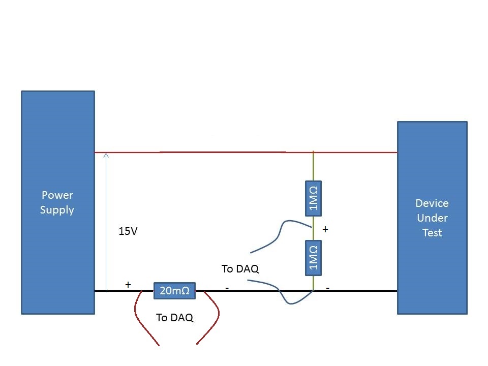
Measurement of the current rail voltage > 10V
Who am I to measure the current and voltage on a 15V supply rail. (Here's a copy of my circuit attatched) I use an acquisition of data USB-6225 and Lab View,
I have my camera to test connected to a power source. I connected two differential channels to the acquisition of data, one for the current and the other for the voltage.
I understand that data acquisition is unable to manage more than 10V so I use a voltage halfway through the voltage divider. When I run the action, the indicated current is incorrect. It shows the 10A when it should be about 500 my.
When I reduce the tension on the power supply 10V, it everything works fine, so I think that its got something to do with the limit of 10V.
Please can you advise how I can connect that places correctly?
Do it this way.
-
Conversion of a "differential" connection for connection "CSR".
Hello
I'm dealing with a measuring system that has already used a "CSR" connection to measure certain voltage signals and it worked well. There is now a new data acquisition (NI USB 6353) and the "differential" connection is used. However, the measures are not more correct.
I know that it would be possible to change the method of connecting to "CSR" as it used in changing the VI but in this case, it would be difficult since I don't have easy access to the DAQ device more.
So the question is this:
Is it possible to manually change a "differential" connection to a "CSR" connection simply by unplugging cables now used GND signal and connect the ports of entry in the GND of the NI USB 6353 ports? This type of connection would be practically the same as using "CSR"?
Any help is appreciated.
Said already that your negatives were all terrain? If you just need to make sure that the reason for your signal corresponds to the ground for the acquisition of data. And to do this, you must connect a pattern of your object to measure data acquisition (IE link your patterns together).
-
Limit NI9215 analog input voltage range
Hello
I use a NI9215 (mounted in a cdaq 9174) to acquire a voltage signal. I want to keep the tension as an integer and then later convert it to a voltage in the script of Fortran. To do this I need to know the relationship between integers and tension. If I use an unsigned integer I 0 is-10 for example (numbers aren't important as long as I know what they are).
I tried to taste a voltage signal (see the attached vi), where I have limit vmin and vmax at the return of V-10 and + 10. When I have a voltage outside this range, waiting for the signal to saturate at-10 or + 10 V, but this does not happen. I generally get +/-10.4 V which figure is the maximum range. This range would have been ok if it was exactly +/-10.4 V but it varies from something on the order of 0.5% between the different channels I use.
Is it not possible to set vmin and vmax that I'm trying to do and if so, what is then the point of vmin and vmax?
Concerning
PAL Egil
Hi pal_egil-
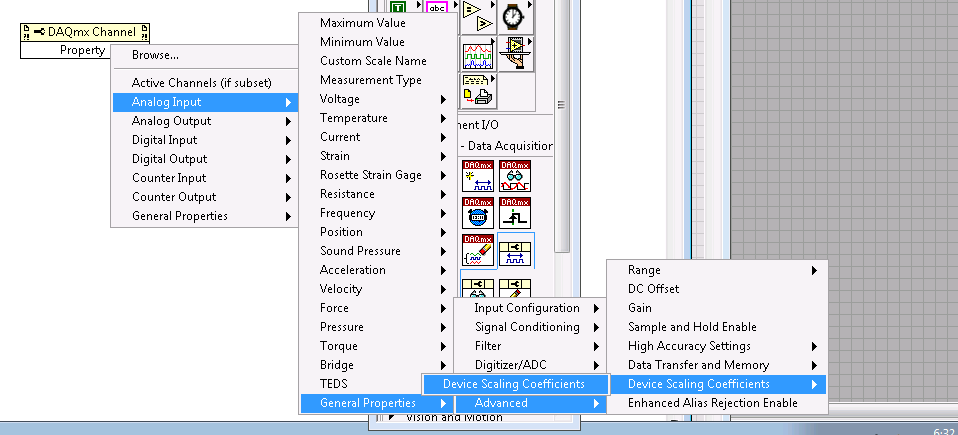
I guess you are trying to save time processor or (perhaps more likely) storage space by resizing the data yourself. I suggest that you use the version of DAQmx Read 'no'. This will give the most fundamental data type available and will save processing time (because it will not be scaling of tension and then re-scaling to an integer value simple on a linear scale of your application) and storage (because you will be able to store a single value of 2 bytes for each data point of your device).
So these unadjusted nationwide tension later readings, you'll also want to connect the device scaling coefficients for your module. These are accessible from the property of DAQmx channel node in LabVIEW, and a description of how to apply them to lectures unadjusted using LabVIEW for NOR-DAQmx.
I hope this helps.
Maybe you are looking for
-
Dear Sir. I have laptop Acer V5-473PG for over a year now and using W8.1. My problem is now (for a month), whenever I start my laptop, the screen goes to "insydeH20 Setup utility". Then I have to press ESC, press enter for 'Yes' and the screen will c
-
Activate WiFi on an Aspire AS33810T?
How can I activate WiFi on an Aspire AS3810T? Is there a switch or function key that does this? Windows 7 says that there is a switch. I can't find.
-
After installing a new printer how to print a test page Windows 7?
After installing a new printer for the operating system Windows 7, right click on the printer icon then properties, there is no choice of test page printed as XP.
-
HPpro 8610: Strange print sizes
I am a user experienced with strange print sizes. However, I just got this new printer (8610 HPpro) and it will not print any "custom": sizes. I get an error message that says that the paper in the printer does not match what is set up in the program
-
HelloI downloaded a program related to forex trading as an EA warning system, but it does not open. I know several people with the same program who do not have this problem. I was able to open it in safe mode but not in normal mode. I am using window