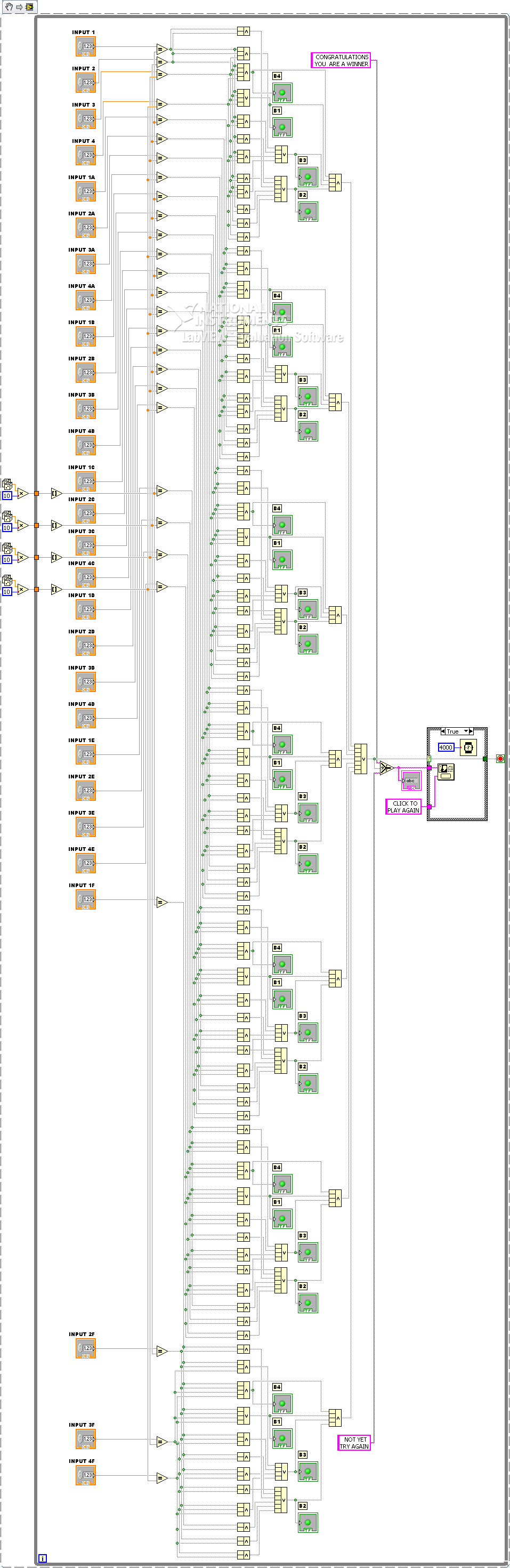
Digital inputs delivered to 0 when all loop stops. Extract attatched
|
Could someone please tell me how do I get my digital inputs on the left hand side reset to 0 when the loop Gets the signal to stop? Very much appreciated |
Here's an easy way to do it.
PS - If I had LV2009 I would download this excerpt and make much more simple or die trying.
Tags: NI Software
Similar Questions
-
Digital inputs only noisy when the laptop is plugged
I had problems with loops of Earth and power supplies for laptop in the past. But it is the first time I got it so wrong that it makes the digital inputs which are both related to the ground and the debounced software cannot be used.
It is NOT material OR. It's a DT9816 of data translation, a USB DAQ Multifunction with small budget. The laptop with the problem is a refurbished Dell, with a very obvious not Dell PSU who throws to the top of the warning in the BIOS and scales back from the processor. (Danger Will Robinson!)

The problem with the digital entries shows only upward on the Dell when it is plugged into a power outlet. On all other machines and with the printer unplugged Dell, digital inputs floating. But those that I have attached to the Earth is rock solid and work very well.
What surprises me is more than the noise is so bad that even tied to the ground with a half second debounce, I get always false triggers. I have not brought to power, but considering that it sounds really loud, I suspect that it looks pretty bad.
I think I'll try a powered USB hub. If this does not work, then I think that the customer will have to replace the power supply on the laptop.
However, I was surprised. I used a lot of USB DAQ hardware, and it's the first time I've never seen a problem like this. The NI USB 6002 I tested on this same laptop does not seem to show the same problems. Even if it is true that this is a different software and the test was brief.
I'm curious to know if other developers have found something similar in the past.
I can confirm that using a USB hub external powered eliminated the problem of noise in the original post.
Interesting things. I had not seen this before. Now, I wish I had again the NI DAQ USB I had here last week so I could test that.
Looks like I'll use a hub powered on this project. But I think I will recommend always replace this power. Although a lot of noise coming from the power supply, probably isn't good for nothing plugged it... or even sitting near him.
-
OR 9403: Digital Input/Output slows timed loop?
Hi all
I use a loop timed sample of 7 current channels (NI 9023), 3-channel (NI 9025) voltage at 1000 Hz in scan mode and it works fine. However, when I add for 8 output channels of the input/output module digital module NI 9403 for timed loop, CAPAS sampling cannot exceed 1000 Hz. According with time stamp data I wroten in file, it seems that I have in all ten milliseconds, I missed a miliseconds.
I would like to ask is there a reason for this? The digital I/o module affect the timed loop?
Thank you much in advance.
I'm not familiar with the FPGA code, so I can't comment there. However, I noticed that you call writing to text file twice in the timed loop. Can you only collect data and then write the files after the time loop? This would save a lot of time. For each entry, the program needs to access the hard disk, find the end of the file, add him and return to write on the hard drive. A lot of your time, especially since the files are getting bigger.
-
9421 sinking digital input module toggles output
I have a digital input module 9421. I'm only using a single port (0). The line is 'high' all the time. I can see it on the lights and the tool MAX. I can turn on/off the line and see the LED and MAX change, so I know I have the cable correctly thing. But in normal operation, it is always powered.
It is, when I run LabVIEW mode trace with a probe on the output ExpressVI DAQ, I see that all the other times my code, the output of flicks from true to FALSE and vice versa... and so on. The acquisition of data ExpressVI is inside a while loop.
Any thoughts?
DH
I have chosen the cDAQ "simulated".

DH
-
Digital input and output problem
Hello:
I do a test for digital i/o:
for a table of the digital signal to an output of data acquisition in the digital input to detect the output signal.
(bascially, it's like a loop that goes outside the material)It's pretty simple, as shown in the attached fichier_1.
It works well.
The manual light switch controls, which means that inputs and outputs are ok.Then I went on the low level DAQ for better speed, as in attached fichier_2.
But it does not work. Especially when I pressed stop to abort the loop, an error has occurred:To speed up, I went to the low-level data acquisition as the fichier_2 attached.
But it does not work. Espeically when I press the "stop"button to exit the loop, the error occurs.Possible reasons:
Requested value is not supported for this property value.
The value of the property may be invalid because it is in conflict with another property.Property: SampTimingType
Asked the value large clock
You can select: on requestI don't understand why the sampling time has a conflict here.
(It is probably just something very simple in data acquisition, but I checked a few examples and did not find a clue).
Hope someone can give me a suggestion.Ultimately, my goal is to make the attached file_3.
In this one, I generate a digital output, and then lead to the entrance.
Then I can take it as a signal to trigger my other task.Note:
I use a similar conti signal to control one of my camera.
I need to sync it with my another task.
So I think to generate a digital output (which share the same clock as the signal similar to the data acquisition device), then put it in one of the digital input.
By detecting this digital input, I can trigger my task and synchronize with this signal similar.
My camera's USB-6211.
I am aware of the latency of USB, but once the value is a constant value, then the synchronization is always good for me.
Actually, I was using an analogue at the entrance of the to do it before, it may work, but the synchronization error is too big for me.
I need to do some calculations/judgment for this analog value, which makes the time difference varies.
So I'm trying digital entry now and I hope that the digital input can trigger my task with a stable latency.Thank you very much
Have you looked at the specs? It clearly states that the digital I/o is a programmed software. You have not any hardware clock at all. The best rate that you could possibly achieve is around 1 kHz and which would have a considerable jitter the nature of non-determimistic of windows.
-
9421 sinking digital input toggles output
I have a digital input module 9421. I'm only using a single port (0). The line is 'high' all the time. I can see it on the lights and the tool MAX. I can turn on/off the line and see the LED and MAX change, so I know I have the cable correctly thing. But in normal operation, it is always powered.
It is, when I run LabVIEW mode trace with a probe on the output ExpressVI DAQ, I see that all the other times my code, the output of flicks from true to FALSE and vice versa... and so on. The acquisition of data ExpressVI is inside a while loop.
Any thoughts?
DH
I had selected "simulated" cDAQ

DH
-
Digital input to Toshiba 46TL-> no analog audio output to amplifier
Hi all
When I connect a video source (e.g. computer laptop via DLNA) to my 46TL, output TV audio analog (red/white taken connected to an amplifier) does not work.
It does, however, watching television.
Is it possible to configure the TV to read the audio data from digital input (HDMI/DLNA) to the analog output?
Thank you for the help
Not quite what series of TLxxx you have, but for example the TL938 supports a digital (optical) audio output port that provides a digital audio signal.
Why n t connect the amplifier to the TV using this Jack?Connectors for component video / audio to the rear of the TV are the ports of ENTRY and not the OUTPUT ports. So, you can send an audio signal to the TV and not the amplifier output.
-
How can I set up a digital input task to read continuous samples?
I am trying to create an exclusively digital task that will make digital readings at a rate timed by the material using a PCIe-6509. However, when I try to put the task timing as follows (which works on a PCIe-6509), I get the following error:
Requested value is not supported for this property value. The value of the property may be invalid because it is in conflict with another property.
Property: NationalInstruments.DAQmx.Timing.SampleTimingType
Required value: NationalInstruments.DAQmx.SampleTimingType.SampleClock
Possible values: NationalInstruments.DAQmx.SampleTimingType.OnDemand, NationalInstruments.DAQmx.SampleTimingType.ChangeDetection
Task name: DigitalInputTask
State code:-200077
The relevant parts of my code are:
public class DigitalInputReader: IDisposable
{
public DigitalInputReader()
{
dataReadyHandler = new System.AsyncCallback (DataReadyEventHandler);daqmxTask = new DigitalInputTask();
daqmxTask.Configure (Globals.NI);daqmxTask.Control (TaskAction.Verify);
daqmxTask.Control (TaskAction.Commit);daqmxReader = new DigitalMultiChannelReader (daqmxTask.Stream);
}public class DigitalInputTask: task
{public DigitalInputTask(): {base ("DigitalInputTask")}
public virtual void Configure (NiConfiguration niConfig)
{
<= niconfig.digitalinputs.count="" -="" 1;="">
{
String physicalChannelName = niConfig.Device + "/ port" + niConfig.DigitalInputs [i]. Port.ToString () + "/ line" + niConfig.DigitalInputs [i]. Channel.ToString ();
String nameToAssignToChannel = niConfig.DigitalInputs [i]. Name;DIChannel ch is this. DIChannels.CreateChannel (physicalChannelName, nameToAssignToChannel, ChannelLineGrouping.OneChannelForEachLine);
c. InvertLines = niConfig.DigitalInputs [i]. InvertLines;
}
var signalSource = "";
This. Timing.ConfigureSampleClock (signalSource, Globals.MachineSettings.SampleRate, SampleClockActiveEdge.Rising, SampleQuantityMode.ContinuousSamples);// Globals.MachineSettings.SamplesPerChannel);
}
}The last call to Task.Timing.ConfigureSampleClock, it's which throw errors.
Of the options available, or SampleTimingType.OnDemand or NationalInstruments.DAQmx.SampleTimingType.ChangeDetection provide the same precisely timed calls that I am familiar with the analog input interruptions.
How is it possible in a digital task? I mean, it seems that I could set up another task to do call by material for the production of a clock signal and use the ChangeDetection synchronization mode, but this seems a bit complicated for what should be easy to do. What Miss me?
Update: I thought about it. You cannot call ConfigureSampleClock when the digital input card is a device of 650 x, because these devices have any automated examples of clock. They are configured to run in mode default finite samples. You must make all sample synchronizing with these devices in the software.
Be cautious, however, because the .NET timers ensure they put any faster than their scheduled interval. In practice, they are usually 5 to 10 ms slow by tick. This means that if you want to read samples every 100 ms by sample clock, you'd end up reading all 108 ms samples. All counters based on the elapsed time and number of samples would be away after a few seconds of it.
Instead, you must do one of four things: write a doggone driver that runs in ring 0 and interfaces with the PCIe card in the required interval (i.e. on NC, not you, in practice), tolerate the inclination of the clock, use a multimedia timer as an interruption audio or video that is more likely to respond to the correct interval, or , my solution, an accurate clock allows you to set the interval of the timer. I wrote the following code to the timer:
var CorrectiveStopwatch = new System.Diagnostics.Stopwatch();

var CorrectedTimer = new System.Timers.Timer()

{
Interval = targetInterval,
AutoReset = true,
};
CorrectedTimer.Elapsed += (o, e) =>
{
var actualMilliseconds =;Adjust the next tick so that it's accurate
EG: Stopwatch says we're at 2015 ms, we should be at 2000 ms
2000 + 100 - 2015 = 85 and should trigger at the right time
var StopwatchCorrectedElapsedMilliseconds = newInterval +.
targetInterval-
CorrectiveStopwatch.ElapsedMilliseconds;If we're over 1 target interval too slow, trigger ASAP!
<=>
{
NvelIntervalle = 1;
}CorrectedTimer.Interval = NvelIntervalle;
StopwatchCorrectedElapsedMilliseconds += targetInterval;
};I hope this helps someone.
-
Hi all
I meet a scenario where the digital input on my DAQ card channel giving 5V when I measure between the channel and the ground. As a result, I was not able to read the digital signal. This happned in the past, a few months ago and my work around it is to switch to another channel. This time, I feel the same thing using my FlexRIO + OR 1483 module. There are four DIO channels and I have them configured so that came in 2-channel and 2-channel output is. Initially, everything worked fine, but somehow, these last two days, I wasn't able to read DI channels. During the inspection, we discovered that DI (at NI 1483) channels provide 5V.
I hope someone could shed some light on the phenomenon.
Please advice.
BEA
Take a look at the spec, maybe a pull from the top of resistance?
-
Raising an event based on digital input? Treatment of a condition of emergency stop
I'm working on a test sequence into LabVIEW. I have a security which I am followed by a digital input the relay status, and I would like to pass to my failed state that I am in a State of emergency. (In my case, this happens when a barrier is broken or emergency push button is pressed).
It would be easy to do if I could use a digital input to trigger an event. However, this doesn't seem to be possible. I tried bind my digital input to a control, and then follow the State of the control as an event, but that doesn't seem to work.
My main problem is that I can be in one of the stages of test 5 seconds approximately. So far, I have not found a way to out or interrupt this step if my digital input changes state. I can get it to transition to the failed state after the step in progress, but I want that it to transition immediately when the safety relay is broken.
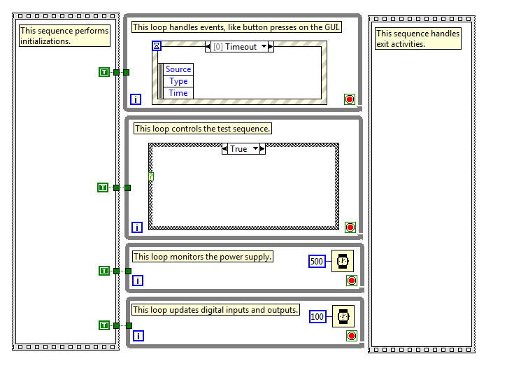
I've attached a picture that shows the basic structure of my program. The actual program is much more complicated, so I hope this is enough information to get started. I have stops in each loop attached together with the help of a subvi, which basically returns a Boolean TRUE if you press the 'stop' on the operator interface (it is one of the events of my structure of the event).
It seems that it would be a fairly common situation that there must be some answer I'm missing. Can anyone help? Thanks in advance...
You need (somewhere) a loop that monitors the digital status and can detect the transition Fail. The timing of this loop of 'surveillance' apply to how fast you can respond to failure.
But now you need to trigger an event when this happens. When I started programming in LabVIEW, I learned on the events of signs of value that could trigger programmatically a value indicator has changed. However, a few years later I learned the user events, a more flexible method for generation "software interrupts' who have a number of advantages over value of signage.
I don't know if you are looking for using LabVIEW or LabVIEW examples user events you'll find a good explanation for how to use these (use the Help Index, and then type user name).
Bob Schor
-
How can I measure the time between each two successive increase edges, using digital input?
Hello
I have tried two measure the time in seconds between each two successive rising edges on a digital input.
So far I managed to detect the rising edge, increment a counter at each rising edge and take the time during which the increase is edge
all I need now is subtract edge currently rising from the previous era of edge rising to calculate (T), which can be 1/frequency and display in real time for the user.
but I do not know how to do this

Can someone help me please!
Woah!
Sorry Apok, but your code becomes much too complicated and salty. I don't think that all records to offset or Boolean conversion/operators are necessary at all.
If you want to measure the time between two keys so it's another (much less complicated) way. It simply records the time when press button in a registry change, then compares the two.
-
Question of the digital input USB-6009
Hello
I use USB-6009. I have problem in Input.I digital did not connect anything on all channels. But all of the DI/O channels generate 5 volts. And I tested the DI/operating system in the Test Panel also. All digital inputs are high. How I use it? Please suggest me the solution.
You're the one who said it was generating 5V. And I said that a fine should be detected as a logic one. Connect a gnd input.
When it starts, all of the default value of I/O at the entrances.
-
I cannot using the simulated digital input function.
I create a digital input simulated in single channel MAX - a simulation NI PCI-6534, port 0/0, mode of acquisition is 1 sample (on request)
When I click on the 'run' button I see the led turn on and turn off, as I expect.
However, when I remove this LbView task, I can not display flashes regardless of what I tried.
Without doubt, I missed some basic notion. Can someone tell me what I am doing wrong?
(VI attached).
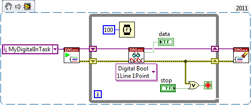
Try starting the task explicitly before the loop (and the task of clearing after the loop):
Best regards
-
Digital input line showing an entry without connected equipment
Hello
I have a feeling, this is a silly question, but here goes. I have the VI below to read the entry of an analogue of the ADC0803LCN to digital converter through 8 lines.
The DAQ assistant is configured to read a digital input for all 8 lines and outputs in a matrix of LED that outputs then a digital indicator to show the binary value.
However even if I don't have the connected equipment and run the program, all lights are lit and on my multimeter I read + 5V to each line. I'm puzzled why I get an output voltage in each line when 'acquire Digital Input' works and why LEDs are HIGH without input logical proof. Even when it is connected to the material, which runs correctly, it still shows all logical LED HIGH with the release of material would not justify this. Any help would be great, thanks. I'm a Newbie, just to be clear
, thanks.Material is - pressure sensor Honeywell Trustability--> ADC0803LCN--> NI USB 6501
Hi beginner,
the answer is shown on page 14 of the Manual of USB6501...
(It is named "PR"
 )
) -
the value of the digital inputs to change the field
Hi all
I have an edit field that has a digital text filter that only accepts phone numbers. Users have the choice to load these numbers from address book or direct entry.
I used the digital filter to allow only numbers. .
But when I tried to load these address book. with editField.setText (phoneNum); It is to throw IllegalArgumentException.
How to set digital inputs to the editField?
Hi thanks for all your entries!
My issued are resolved. I used BasicEditField aulieude EditField to solve this problem. the basicedit field allows the digital text and it solved the problem.
Thanks for all your interest...
Maybe you are looking for
-
I just bought from Future Shop a HP ENVY Pheonix 810-209 Telechareger 12 concerts memory intel i7 - 4770K My Question is I have 3 monitors to my current setup that I want to connect. Digital for all This office shows that it is the following graphics
-
How long the defragmentation take?
I have a Dell Inspiron with Windows Vista, and I started a defragmentation of disk more than twelve hours ago. Is this normal? The PC is fairly new (3 months) and am the only owner and user of it. This is the first time I've run a defragmentation; It
-
BlackBerry Smartphones Spell Check disappear
Hi all. I have an interesting situation and could not find the answer here or on BBforums.com. One of my users, who use an AT & T 8310, orthographic corrector function, is missing almost completely. After the failure of your handheld, it will be ther
-
Allowing roaming between Standalone AP wireless
Hi all I am about to purchase 2 Aironet APs, or 1140 or 1160 series for a small business. I know too little about the installation of the AP. Can someone guide me how to leave the two APs roaming works so that users can move freely on the site withou