Drag poles zeros of a bode plot curve
Hi all, I have a program of field bode, who can draw magnityde vs frequency and phase frequency vs like this.
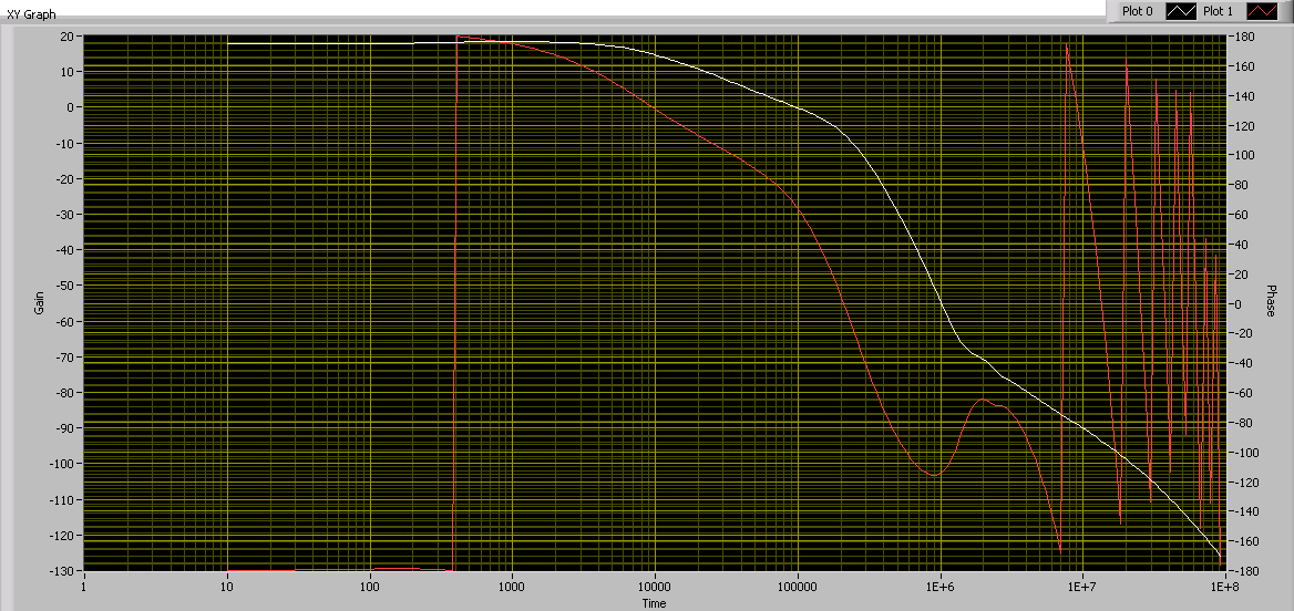
This bode plot is based on the functions of the poles and zeros. Here is an example showing how to calculate Labview zeros/poles. All values of R and C can be entered by the user.
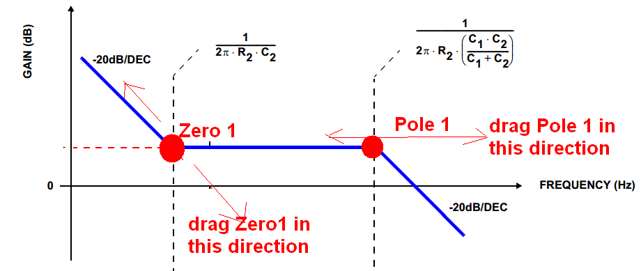
Now, I am trying to add a function like this:
(1) the user can use the mouse to drag these two points according to their orientation specific as what this picture shows. When these two points are moved, the shape of this curve will automatically adjust.
(2) when the user finishes placing them, Labview can detect their location, and then use the equation to understand what value curent R and C.
Can someone advise how to implement this function? Thank you very much!
Hello
What you're trying to sounded so cool, I thought I'd have a quick go.
I downloaded a very simplified example, which involves programmatically set values in an equation, by dragging a slider on a XY Chart.
If all goes well, this should give you an idea how to do what you want.
Here is the link.
https://decibel.NI.com/content/docs/doc-29647
Good luck
Tags: NI Software
Similar Questions
-
Graphic cursor size does not respect the Bode plot
Hello
I was wondering if someone would be able to shed some light on a problem I'm having about a graph XY cursor.
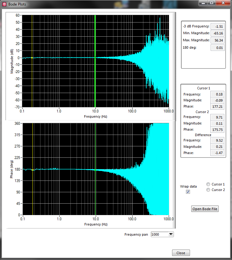
I developed a simple VI to determine the characteristics of a low-pass filter through which a sinusoidal signal ramp frequency and subsequently followed the gain of the filter to create a Bode plot.
Through the analysis of the curve of Bode I want to determine the cutoff frequency of depression go the filter under test. I introduced a slider in the chart and using a property node I have hoped to set the cursor to-3dB point in the Y axis and the corresponding sliders X post thus determining the cutoff frequency of the output filter.
However the slider seems never to follow the plot beyond the first stage of the loop. It feels as if there is a break in the conspiracy between the 1st and 2nd iteration of the while loop used for the ramp signal generator.
I tried to find why the cursor won't follow the plot at-3dB, but so far I am confused.
Any help or advice you could provide would be greatly appreciated! I have provided the attached VI for clarity.
I corrected your VI.
First of all, you need to put the property node AFTER the while loop, because you need the chart to be done first and then watch the cut off frequency.
Secondly, in LV, property nodes are read from top down. So you have to move the cursor to Y =-3 first, and then read the X position.
I have attached the corrected vi
-
Problem with pole-zero analysis using multisim
Problem with pole-zero analysis using multisim
Party a pole / zero analysis is linearizing circuit using an operational RODC analysis, in which a driver acts as a short circuit. The problem is that in your circuit, the inductor in parallel with a source of internal tension unit.
Use a small resistor (1mOhm will do in your case) in series with the generator output functions to break the loop short-circuit.
-
Hello!
I am trying to plot of Bode a PID connected with my myDAQ NOR in LabView 8.5. Does anyone know how to connect the ports of the myDAQ in the program?
I'm not able to use NI ELVISmx Instrument Launcher.
Thank you!
Sincerelly,
Petra
-
How to make a scatter plot curve smooth?
I do a diagram of dispersion plot, with the values supplied for the diagram.
I plugged all the points on the line, but I get these 'sharp' corners whenever the curve changes direction.
How can I make cela a smooth curve?

Thank you
Convert anchor points using the pen path tools.
Mylenium
-
ground surface zero pole to read data (number of data 700) 1 d
I would go for the transform of real data (number of data 700) 1 d Laplace and the plot of surafce pole zero for pic showing the poles.
Can someone help me
Thank you
AK
Hello cory:
After laplace {x}, how can abs suface (laplace {X}) which will give me a pic of pole zero in 3D surafce (s palne).
Thank you
AK
-
I'm developing an application to test the hardware components designed by my colleague.
My application can read signal from the material and data flows in a log file. In addition, I can order the supplies to perform a frequency sweep on one of its input signals. So I have the ability to connect to the input signal frequency sweep, but also a corresponding output signal.
I can then do two things with the file:
- Read the log file and read the signals on a strip chart. I have adjustable low-pass filters to reduce noise on the raw, if necessary.
- Read the logfile of a signal frequency-swept, to execute a transfer function on two selected signals and plot the data obtained on a size-v-freq and a graph of log phase-v-freq, aka Bode plots scale.
My problem is that my Bode plots are sometimes noisy, and I don't know how I should go about their cleaning.
Here is an example:
I know that the swept frequency input signal by was loud himself, so I thought to pass through a low pass filter before plotting, but it does not make changes.
I also saw all the options of the CVI curve adjustment, but I'm not competent in whether or not it would sense, especially for phase-v-freq graph, as its shape is indefinite.
Someone can push me in the right direction? I am sure there is information I provide not as well.
Hi Rachel,
For the example I provided, the input signal is "raw" unfiltered data. What it really is is forced to low sinusoidal voltage, which is summarized with the real signal on that channel on the material (which is the white noise of low voltage). For the purpose of our tests, we use the free entry and exit, and the output channel is simply the input channel put through a low pass filter. We see a (smoothed) sine wave phase shifted silent for output.
After a long discussion with my colleagues, we think we know where we went wrong with this example.
As I said, my application command equipment to do a frequency sweep. It is to reproduce what seemed the signals when my colleague uses his material (Venable) commercial frequency response Analyzer, which at the end of the day, we try replace by my application. How I got this set up has been the input signal would spend cycles N of a sine wave at the frequency f = Fstart, then f would increase percentage P cycles N to f = Fmax. N and P would remain constant.
We realized that if we kept constant N, us would collect enough data to higher frequencies, which is probably a lot of noise at higher frequencies due to the low SNR of the input signal. We believe that this could help clean up the ground, but we could still have a fundamental problem with how we have tried to make the TransferFunction.
I logged on to the whole of the file, would have extracted all input and output signals and performing the unique function of transfer on 2 tables of the data set. I think that we became aware that the error in this method is that while signals (in the time domain) seem to be reproducing the Venable, the Venable analyze each individual f step and produce a data point for the route of Bode. We now believe that this is how the CVI TransferFunction function must be used. That is, providing instead a signal complex (y = sin (f0) + sin (f1) + sin (f2) +... + sin (Fmax)). It would be too resource-heavy for our material.
If someone can confirm if it is the right way to use the TransferFunction, it would be very appreciated...
-
XY graphics cursor doesn't snap to draw when you drag
I have not used the XY graphs a lot and need to have several locations on the chart and be able to find the points on the path value using cursors. Everything works fine except that I can't drag the cursor along the plot. Even if Snap to is on and drag is enabled when I drag it not release to the plot. When I then use the navigation arrows pointer if drag hangs on the last point, that he had on the dredge instead of flapping in the plot during the operation. I want the user to be able to drag the cursor and have it align with the plot, it is attached. Any help would be appreciated.
I have attached a simple example of VI.
You use a structure of data without papers for the multiplot. (an x, y, for example as here).
Every plot needs it's own x!
If you do the following, things work fine. (even if you use bundle, of course)

... and please add a wait at one loop. It is not actually necessary. Sliders lock even back in editing mode, of course.
-
The XY graph Plot.LineWidth Property node problem
Hello!
I have a loop, where I repeatedly putting curves in a XY Chart. In the first iteration of the loop, after the first corner appears on the graph (I send data from the graphical indicator), I use a Plot.LineWidth Property node to align the thicker. However, in the next iteration, when the second plotted curve appears on the graph, and the property node is pulled again, the second curve remains thin. I guess what I've done wrong, that this property node defines only the first curve? How can I set the width of the line of all the curves of the XY graph on the same value? When I directly on the properties of XY graph, I can set the width of the curve, but only one by one...
Suggestions how set the widths of the ground on a specific chart XY?
Thank you!
If it is a multiplot XY, you must set each plots properties by using the property activeplot (index of the new lot), then by setting the thickness.
-
I have a square or polygon. I want to turn one side of right of a smooth curve. Is there a way to do this?
I have the pen tool and I am followed by an object. I want to create a side curved, then continue on straight edges. However, the tool insists on the creation of curves of 2 or 3 at a time.
Is there a way to create a single isolated or part of a curve shape that is adjustable with the two endpoints. It seems that the curves that I often creates lack levers to one of their ends, making it more difficult to get the shape I want.
I have a square or polygon. I want to turn one side of right of a smooth curve. Is there a way to do this?
ALWAYS indicate what version of the program that you are using. Assuming that CS3 or later:
(View > snap to Point on)
1 white pointer (the so-called Direct Selection tool): select the anchor of interest points.
2 Control Panel (this strip along the top of the window): click on the smooth button convert. The anchor is changed into sweetness; the two Direction handles auto-étendre.
3 white pointer: drag the handle unwanted in the anchor.
or...
3 convert Tool: click the handle unwanted.
I have the pen tool and I am followed by an object. I want to create a side curved, then continue on straight edges. However, the tool insists on the creation of curves of 2 or 3 at a time.
1 pen: click. (Put a corner Point).
2. move the slider. ClickDrag. (Place a smooth Point, curved segment results.)
3. click on the anchor you just placed. (Cut off the outgoing handle.)
4. move the cursor. Click on (places a corner Point, the line segment results.)
Is there a way to create a single isolated or part of a curve shape that is adjustable with the two endpoints. It seems that the curves that I often creates lack levers to one of their ends, making it more difficult to get the shape I want.
1 pen: Click (puts a corner Anchor Point.)
2. move the slider. MouseDown and drag. (Puts an anchor of smooth, curved segment results.)
3 press and hold ALT continues to slip. (Coming out of the handle under the cursor moves independently the incomming handle.)
4 Mouseup. Move the slider. Click or ClickDrag to set the next anchor point.
There are other ways to make a little of what precedes, by pressing the shortcut keys to move to other tools. For example, when drawing in pen, you can press Alt to call the tool convert a temporary anchor point and drag a handful of pre-existing SmoothPoint and its opposite handle move independently (anchor of the so smoother conversion in a corner Anchor Point).
One of the weaknesses of the Illustrator in this (apart from boredom in all of comparison) is its inability to drag a handle retracted on a corner point retracted to bend an existing right segment.
There are 3 different types of anchors - straight, smooth (two direction handles work in alignment) and cusp (two handles of direction working independently).
N °
Illustrator interface defines two types of anchor Points: corner or smooth. What you call a "cusp point" is just a CornerPoint with one or two of its scope handles. 'Dawn' (kind of a Bézier control point) is a relevant term of Corel Draw, Illustrator not.
Illustrator: Smooth corner Point, Point
Draw: Cusp node, smooth node, node symmetric (Illustrator does not provide symmetrical behaviour.)
Scribble: corner Point, curve Point, Point of connector (Illustrator does not provide the behavior of connector).
JET
-
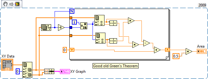
How to calculate the area of a XY graph
I have build a process assessment program and got stuck on it. I have a chart XY of the angles of knee hip x and need to find the area of the plotted curve. I searched the forums, but found no way to do it. Any ideas?
Green theorem comes immediately to mind:
I cut the first two points to make the graph more cyclical and 1300.36 for the answer. That passes the eyeball test, but you should double check my implementation of rapidfire (and my memories of summary calculation).
-
Simple question about an increase in the frequency
I do a simple bode plot that will be used by a class of electronics. All I need to know is how to have a frequency input I can change after a delay loop. I would like to change the frequency of 100 Hz by loop.

-
error "thread: belongs to a cycle.
I do decoupling control of MIMO system in the LabVIEW Control Design and Simulation module. Simulating the controller and the transfer of plant functions, gives error "thread: is a member of a cycle. I understand that it is coz of three transfer functions in the matrix trnsfer having as many poles & zeros showing a direct supply through behavior. Can someone that I can't make any changes in the factory or controller models, suggest a possible solution for this? Please
[email protected] wrote:
It would be more convenient to have a code.
krishnapriyapg wrote:
Mr President, out of the 7 is given to the negative node of the summer near the SP level (to 10). In the comic book, it seems that both are given to the same node is just a mistake that happened while cleaning the threads in the diagram. However, the connections are correct. I have attached the screen again.
Well, that's your cycle: "the release of the 7 is given to the negative node of summer near level SP (10). You must insert a feedback node it and initialize it to 0.
Ben64
-
Values that are unwanted in a graph
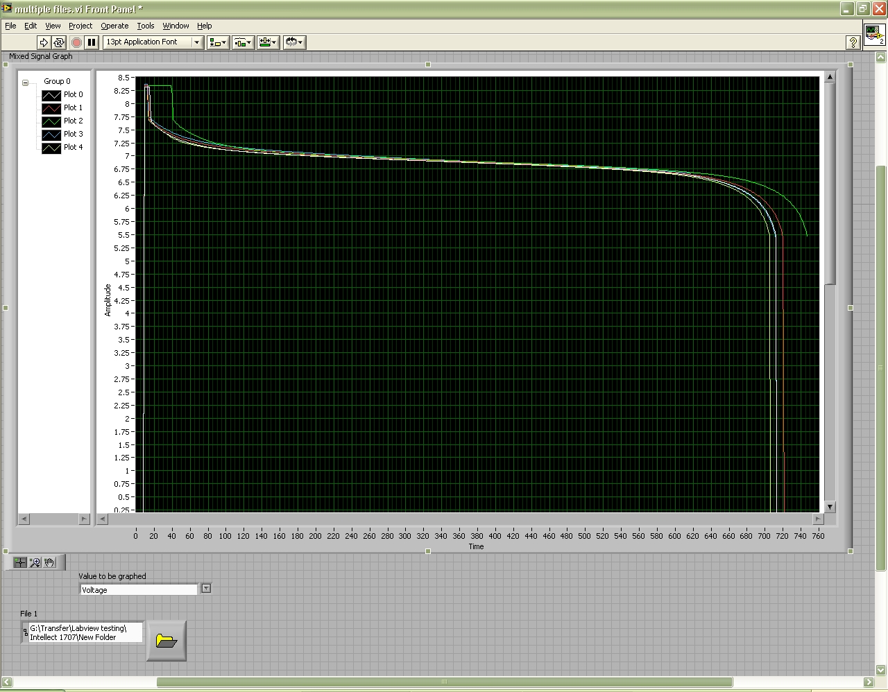
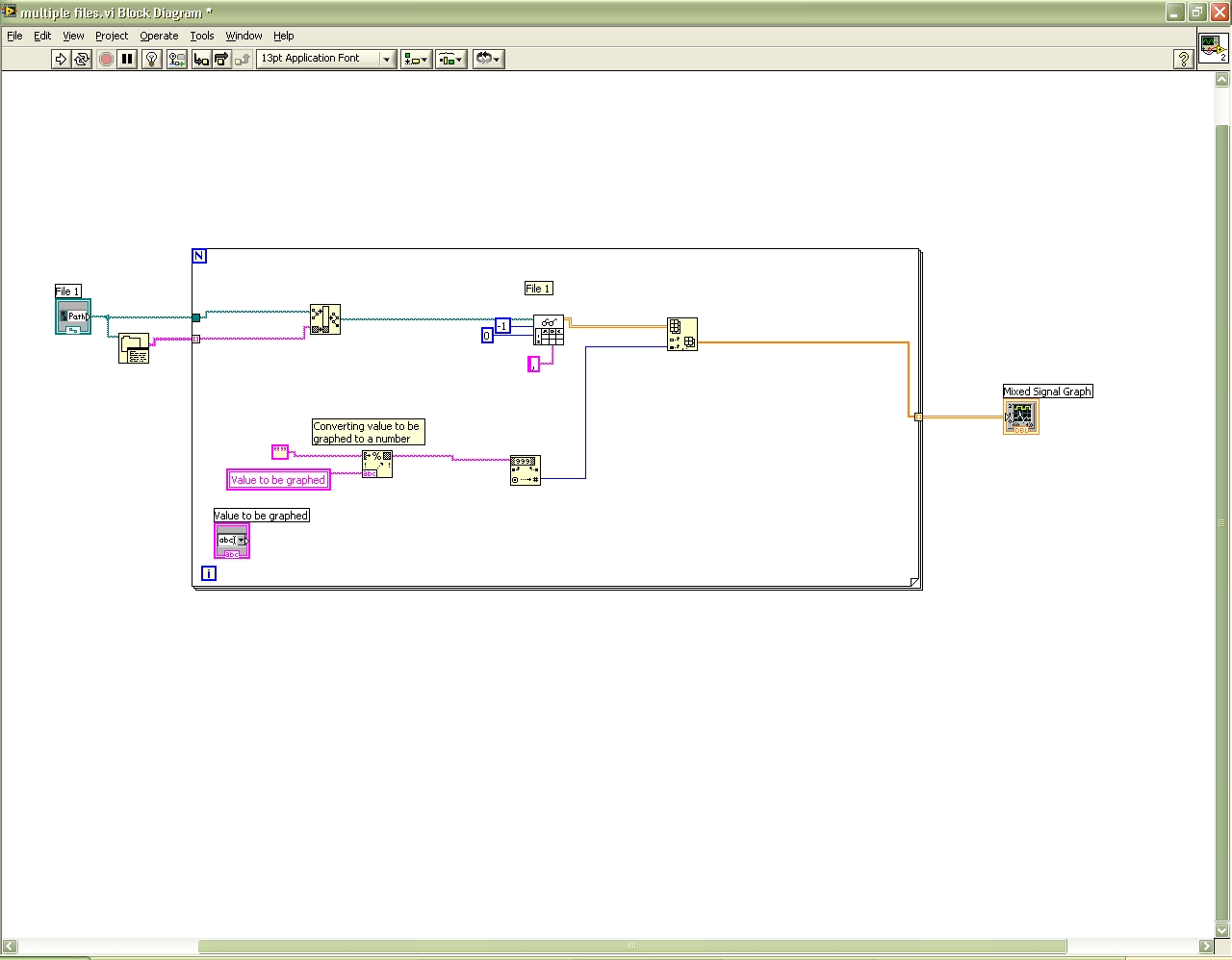
I have a program that reads multiple spreadsheet files and plots the data of each file on a chart. The problem I have is labview is tracing the zeros that do not appear in the file, making the graph does not look right. Attached are 2 screenshots, one of the block diagram and the other of the façade.
If you look at the chart on the front panel, you can see the white track starts at zero when the other plots are not. You can also see that all plots, with the exception of one green end to zero as well. I'm doing all the plots are similar to the green.
Thank you!
-
I'm having a problem with the pen tool recently. the pen tool doesn't let me do the sharp edges or horns.
for example.
I try to do that.

And I am doing this: I

See how the pen tool will not let me do the curve?
It is a huge problem, because I want to do logos and I can't.
If I'm doing something wrong, or using the wrong tool please tell me the correct way.
I should also add the alternative way (which seems a bit lengthy compared to above, but who can help with a different design)
Start up and going counterclockwise
Click on the highest point of the page
Click the second (straight line)
Click on the third (straight line)
Click and drag in the fourth (to create the curve)
ALT click on the fourth point, which you have just created (which removes the handle facing forward)
Click and drag to the fifth (to create the curve)
ALT click on the fifth (to remove the handle facing forward)
Click on items 6 and 7 (straight)
Click and drag the 8 (curve)
ALT click on the 8th (removes the handle facing forward)
Click and drag the 9 (curve)
ALT click 9 (to remove the handle facing forward)
Click on the 10th (straight line)
Click on the starting point (straight line to close the loop)

Dave


Maybe you are looking for
-
Pavilion g6: button Wireless stopped working on laptop HP pavilion g6
The wireless button has stopped working on my g6 pavilion. I read that some people have had this problem.Anyone would be kind enough to help out me.Thank you
-
Satellite T110-107 - need driver for ACPI\QCI0701
Hello I just reinstalled a fresh copy of windows and I can't find the driver for ACPI\QCI0701Tell me which driver should I use Fine thank you
-
Labview Newbie question: Table of clusters
1: I am a student 2: this isn't homework or a project classified 3: I'm a programmer capable enough, but it is in the textual languages. ;-) I have a sensor that contains 4 channels of power. I need to keep all 4 active channels, but I want to choose
-
CD/DVD getting not recognized with error code 0 x 8007003
Original title: Windows Media Player my lap top will not come CD dvd I used microsoftxit as fair, he told me that it can not detict cd dvd and error code 0 x 8007003 can do everything what it means please
-
What happened to the XP powertoys?
Hello I have windows xp. I reinstalled the operating system. I had a few power toys installed before. I can't find now them to reinstall them. Specifically, I want the disktop Magnifier. I could not find on the microsoft Web site. Anyone know w