LabVIEW, myDAQ, Bode plot
Hello!
I am trying to plot of Bode a PID connected with my myDAQ NOR in LabView 8.5. Does anyone know how to connect the ports of the myDAQ in the program?
I'm not able to use NI ELVISmx Instrument Launcher.
Thank you!
Sincerelly,
Petra
Tags: NI Software
Similar Questions
-
Drag poles zeros of a bode plot curve
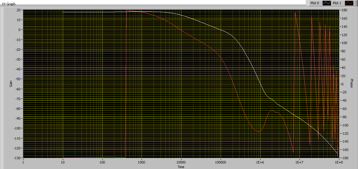
Hi all, I have a program of field bode, who can draw magnityde vs frequency and phase frequency vs like this.
This bode plot is based on the functions of the poles and zeros. Here is an example showing how to calculate Labview zeros/poles. All values of R and C can be entered by the user.
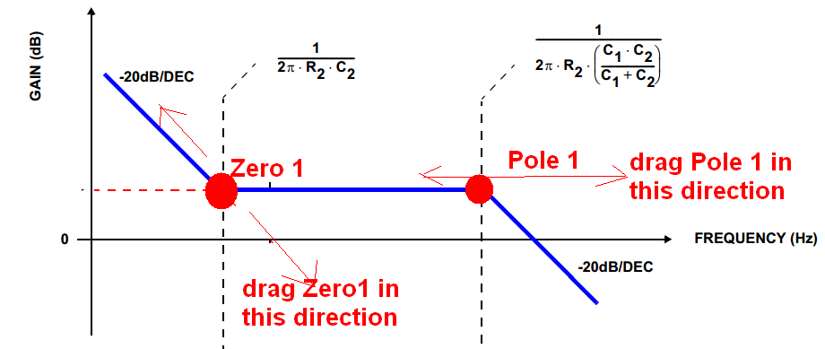
Now, I am trying to add a function like this:
(1) the user can use the mouse to drag these two points according to their orientation specific as what this picture shows. When these two points are moved, the shape of this curve will automatically adjust.
(2) when the user finishes placing them, Labview can detect their location, and then use the equation to understand what value curent R and C.
Can someone advise how to implement this function? Thank you very much!
Hello
What you're trying to sounded so cool, I thought I'd have a quick go.
I downloaded a very simplified example, which involves programmatically set values in an equation, by dragging a slider on a XY Chart.
If all goes well, this should give you an idea how to do what you want.
Here is the link.
https://decibel.NI.com/content/docs/doc-29647
Good luck
-
Graphic cursor size does not respect the Bode plot
Hello
I was wondering if someone would be able to shed some light on a problem I'm having about a graph XY cursor.
I developed a simple VI to determine the characteristics of a low-pass filter through which a sinusoidal signal ramp frequency and subsequently followed the gain of the filter to create a Bode plot.
Through the analysis of the curve of Bode I want to determine the cutoff frequency of depression go the filter under test. I introduced a slider in the chart and using a property node I have hoped to set the cursor to-3dB point in the Y axis and the corresponding sliders X post thus determining the cutoff frequency of the output filter.
However the slider seems never to follow the plot beyond the first stage of the loop. It feels as if there is a break in the conspiracy between the 1st and 2nd iteration of the while loop used for the ramp signal generator.
I tried to find why the cursor won't follow the plot at-3dB, but so far I am confused.
Any help or advice you could provide would be greatly appreciated! I have provided the attached VI for clarity.
I corrected your VI.
First of all, you need to put the property node AFTER the while loop, because you need the chart to be done first and then watch the cut off frequency.
Secondly, in LV, property nodes are read from top down. So you have to move the cursor to Y =-3 first, and then read the X position.
I have attached the corrected vi
-
"print" command in Mathscript recording is not the plots in BMP format!
Hi guys,.
I am creating a vi that automatically generates a pdf for my project report. I found a way to record the report directly in pdf format (in other words, I have 'print' my report to a (PDFCreator) Virtual PDF printer that saves the file in a specific folder with the date/time under his name.) "So, this was the first step to make the automatic procedure).
I'm stuck in the next step, which is adding to the report no graphics bad appearance of labview, but the plots of the victims of the Mathscript.
Yes, after you have added as input 'a' my data to the mathscript node, I use the following commands:
Figure
Plot (a)
print the image
Now, what is this sequence is to do a beautiful land of my data and then save it as "image.eps" in the default folder.
However, the eps format is not at all useful to me because I can't import the plot with the 'Add Image to Report.vi '. This vi supports the formats BMP, GIF, WMF, EMF and JPG only.
So, I want to save as BMP mathscript plot. It's supposed to be possible, but I have not been able to find a way. Using the command 'Print' for Labview Mathscript 2011 reads as follows:
http://zone.NI.com/reference/en-XX/help/373123B-01/lvtextmath/msfunc_print/
Syntax
print
Print (a)
Print (file)
printing (, file)
Description
Print the trace window, or save it in a file in BMP or EPS format. If the trace to save window is a plot of the image or a 3D terrain, the file must be in BMP format. Other types of plots, formats BMP and EPS are supported.
There is no way for me to choose what format I want, and it automatically selects the eps. If I use the command
print image.bmp
It gives me an error. So adding the endpoint .bmp is not the way to go.
Overall, it is essential for me to export the plot in BMP format (in order to import it into the generation of report), but I can't find a way, althouth it is supposed to work.
Any ideas?
Thank you
PS. I run Labview 2011 SP1
Hello
You must use the following command
Print ('test.bmp')Instead of
print test.bmp
-
I'm developing an application to test the hardware components designed by my colleague.
My application can read signal from the material and data flows in a log file. In addition, I can order the supplies to perform a frequency sweep on one of its input signals. So I have the ability to connect to the input signal frequency sweep, but also a corresponding output signal.
I can then do two things with the file:
- Read the log file and read the signals on a strip chart. I have adjustable low-pass filters to reduce noise on the raw, if necessary.
- Read the logfile of a signal frequency-swept, to execute a transfer function on two selected signals and plot the data obtained on a size-v-freq and a graph of log phase-v-freq, aka Bode plots scale.
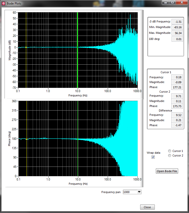
My problem is that my Bode plots are sometimes noisy, and I don't know how I should go about their cleaning.
Here is an example:
I know that the swept frequency input signal by was loud himself, so I thought to pass through a low pass filter before plotting, but it does not make changes.
I also saw all the options of the CVI curve adjustment, but I'm not competent in whether or not it would sense, especially for phase-v-freq graph, as its shape is indefinite.
Someone can push me in the right direction? I am sure there is information I provide not as well.
Hi Rachel,
For the example I provided, the input signal is "raw" unfiltered data. What it really is is forced to low sinusoidal voltage, which is summarized with the real signal on that channel on the material (which is the white noise of low voltage). For the purpose of our tests, we use the free entry and exit, and the output channel is simply the input channel put through a low pass filter. We see a (smoothed) sine wave phase shifted silent for output.
After a long discussion with my colleagues, we think we know where we went wrong with this example.
As I said, my application command equipment to do a frequency sweep. It is to reproduce what seemed the signals when my colleague uses his material (Venable) commercial frequency response Analyzer, which at the end of the day, we try replace by my application. How I got this set up has been the input signal would spend cycles N of a sine wave at the frequency f = Fstart, then f would increase percentage P cycles N to f = Fmax. N and P would remain constant.
We realized that if we kept constant N, us would collect enough data to higher frequencies, which is probably a lot of noise at higher frequencies due to the low SNR of the input signal. We believe that this could help clean up the ground, but we could still have a fundamental problem with how we have tried to make the TransferFunction.
I logged on to the whole of the file, would have extracted all input and output signals and performing the unique function of transfer on 2 tables of the data set. I think that we became aware that the error in this method is that while signals (in the time domain) seem to be reproducing the Venable, the Venable analyze each individual f step and produce a data point for the route of Bode. We now believe that this is how the CVI TransferFunction function must be used. That is, providing instead a signal complex (y = sin (f0) + sin (f1) + sin (f2) +... + sin (Fmax)). It would be too resource-heavy for our material.
If someone can confirm if it is the right way to use the TransferFunction, it would be very appreciated...
-
Simple question about an increase in the frequency
I do a simple bode plot that will be used by a class of electronics. All I need to know is how to have a frequency input I can change after a delay loop. I would like to change the frequency of 100 Hz by loop.

-
I am a student trying to buy labview 2013 online. I found a site selling labview 2013 which has a very good price. http://www.studica.com/national-instruments-students-NI-LabVIEW-mydaq/LabVIEW-Student-Edition.html I just like to make sure that it is a real deal. Any comment?
NOR even said, that you can buy to studica, see here. So this should be a real deal.
-
extract data from record of an E5061B Analyzer
We have a document from third party showing a Panel before Labview with the plot of an Agilent E5061B Analyzer use. So we think that this is possible.
We have a parser to use Agilent E5061B. LabVIEW 2014 runs on win7 pc and using a USB GPIB interface. And her example .vi "Agilent ENA series gain trace.vi, Agilent ENA series interactive application.vi, acquired E5061B trace" we can get Labview to retrieve field data from the parser to use Agilent E5061B.
Dose anyone install Labview on Analyzer here?
Any ideas?
Thank you
Use the help > find instrument Drivers.
Orders for sustainable intensification of CROPS that uses the driver are all listed in your manual.
-
Hello.
I spent the afternoon looking for a solution to my problem in this forum but I did not yet find.
I need to draw points to a picture on a picture 2D and until now, I tried with 'Trace XY VI', 'Attracting Point VI' and this one:
With the first VI I get lines instead of simple points. With the other, the drawn pixels are too small and I can barely see them. Even with the third argument.
Anyone know how to plot more big points?
Thanks in advance.
In the thread, you have access, CC suggested using the oval Overlay IMAQ VI to draw larger circles to these points. Have you tried that?
Also, should you use IMAQ or you can use the image control screws?
-
How to cut a pieces to each saw tooth waveform?
I spent a lot of time trying to tackle this problem and hope someone can offer a useful overview. I have attached the VI described here.
I am using an NI USB-6212 data acquisition-related Labview to create a voltage ramp, which results in a laser through its analysis. The laser is pointed at a detector, and at the same time, I read in a signal of the detector using the same DAQ. Because the detector is illuminated by the laser, it shows the scan pad. I would like to repeat what voltage scan and read - in indefinitely. A large part of this system works. I used the "RampPattern.vi" to create a sawtooth wave, which is exit with success the acquisition of data. As expected, the entry of the sensor shows the same trend sawtooth. However, I am having a lot of trouble dealing and displaying the digitized seesaw of the sensor, which is currently read in as a waveform.
The challenge that I can't move is manipulate or collection of the tooth of saw so that I can do two things:
(1) view the entrants saw tooth a 'tooth' at a time. Each saw tooth represents a laser scan and I would like to see the ramp to scan incoming as a single slope, not a series of sawtooths. Ideally, as each analysis came, he would replace the previous analysis (as in the "Graphic" Labview), while the plot would show a stationary scan that would flicker to the entrance of the last analysis.
(2) divide the entrants on each table ramp sawtooth never updated that can be followed with mathematics, stored in a file, functions etc.
I have a feeling that it wouldn't even be a back of a donkey for an experienced user, but I was hooked on it. Could I collect the analog signal entering the detector into pieces that are the length of each ramp? I could an event at each ramp that would split the waveform in a table?
I am open to any suggestions! I thank you for the input and help,
Sam
Problem solved!
The solution was to wire the parameter 'number of samples per channel' in VI of reading DAQMx. I put the 'number of samples per channel"number of points to each scan sawtooth (this is the same value as 'number of waveform samples", used to generate sawtooth in BasicFunctionGenerator.vi).
The analog playback VI DAQMx now reads a sawtooth, both. The waveform graph shows each saw tooth, at the same time as they appear. Also the output waveform has the appropriate dimensions (the duration of the analysis), and I can perform mathematical operations on each single sweep.
Works great! I posted the working code.
-
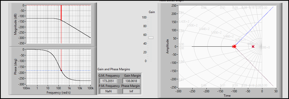
I just installed the evaluation version of LabVIEW and LabVIEW Control Design and Simulation Module 2013. Normally, for the design of command I only use Matlab/Simulink but LabVIEW has some advantages and I want to enjoy these benefits. The problem, I think it's boring, it's that I can't use the money controls to change the default control style classis - like bode gain and track of lotus of margin or root below phase
Hi muahang,
Why not? What is the problem here?
These plots are like XY graphics standards (maybe with graphs from bottom fantasy for the locus of the root)...
-
Good wiring when using Bode Analyzer with myDAQ
Hello
I'm trying to measure the frequency response of a lowpass butterworth filter 4 pole.
I use the myDAQ and Bode Analyzer software.
How to wire AO 0 and AI 0 to measure properly?
My simple understanding tells me to connect AO 0 at the entrance of the filter and GOT 0 + to the output of the filter and HAVE 0 - to the mass.
This produces strange results, and I think that something is wrong with the wiring.
Am I supposed to use AI 1 +/-in a sense?
Thank you.
You will need to wire them HAVE 0 and AI 1. The Bode Analyzer resembles the input and output of the filter and the caclulates response of 2 analog inputs. Since the entry to the filter can come from any source, the myDAQ, the parser must read the value at the entrance as well. That's why DO 2 channels is necessary.
AO 0 and AI 0 + will be connected to the input of the filter. HAVE 1 + will be connected to the output of the filter. 0 - AND AI 1 - will be wired to ground.
-
Where can I find the Helper of Plot Bar 3D LabVIEW in 2014?
Hi all!
Sorry if this question is trivial. I know this is supposed to be pretty simple. However I fail to solve the problem.
I need to generate a 3D bar plot. For this, I found the attached example VI: 3D bar with custom labels chart 2013.vi. I tested this 2013 LabVIEW VI and worked perfectly. However, I have to work with LabVIEW 2014 (German edition, SP1, f3). When I opened this VI with the 2014 version, I get a broken VI.
I realize I don't think 3D Helper.vi of Plot Bar where I used to find it in the version of 2013 in my 2014 LabVIEW (see image of attachen). In addition the broken VI seems not to recognize the custom 3-d bar graph indicator.
I appreciate any help you can provide to me!
Sincerely,
Diego
Hello everyone!
I just found the cause of this behavior. The Helper of Plot 3D Bar is not available in the basic development system. It was possible to see in the 2013, because it was a trial version where the VI is available!
Thanks anyway!
Diego
-
TestStand and LabVIEW treat differently polymorphics with instances with bodies of private classes.
I have a class of LabVIEW and the class contains a method that is a polymorphic VI, and that polymorphic instances has. If I put the scope of Private, and the polymorphic bodies access to the public, then I can force developers who use the class to use the polymorphic VI (and not to call directly the instances). It's great. I like that.
but...
I have build a TestStand API that uses a polymorphic and instances as described above. I create a time of LabVIEW, with a type of call class member, and I target my class. TestStand does not support polymorphic VIs, meaning that polymorphs or its instances appear in the name of the Member list.
This means that, to support my LabVIEW users and my TestStand users, I need to create two separate APIs, which is not a place of happiness to be. No matter who encounter this and found a solution? Or I'm looking at this wrong?
It dawned on me later that we could actually change TS to be a static link to a particular instance VI via the polyVI. After all, you can manually select an instance specific polyVI. It would be just a way to declare in TS "link to this particular instance of the polyVI." Allowing the TS to say "I'm going through a public interface to join a private function."
So instead of linking "A.i" you could bind to ' PolyVI.vi: A.i ".
-
Sensor using IR Sharp 2Y0A21 to enter data in a labview program using mydaq
Hello
I'm working on a LabVIEW project. A portion of it (creating a sub - VI), I want to make use of a record international sensor (SHARP 2Y0A21), in order to measure the proximity of my hand from the sensor. I also have the myDAQ to help me with the sensor inputs. I want to make a program that turns a Boolean LED on when my hand is out of range of the sensor. Please guide me as to what I have to do to make it work. A few steps on how to make my program will be highly appreciated!
Thank you
Ksquared.
Hi KSquared,
This article by DeveloperZone, measure the Distance with myDAQ and Sharp IR proximity sensor should help you get started. Although the model of sensor used in this article is different, the specifications seem to be very similar suddenly look at the data sheet. If you follow this link, you should be able to acquire the output voltage of the sensor, filter and convert the voltage up to a distance. From there, the rest of your program should be fairly simple to complete. Feel free to post any other questions you may have about the article or your application. Hope you find the article useful!
Maybe you are looking for
-
How can I delete a tab in the Session Restore?
After that Firefox crashes, I sometimes get a message suggesting to delete one or more tabs to restore my session. I tried to highlight > delete, which did not work. I tried to highlight > and 'restore' in the upper part of the column to remove the c
-
R200-110 - boot from external CD player
How can I start r200-110 external cd-rom?
-
Service Pack2 is offered several times.
vista update I updted vista SP2 successfully, but I still get a rquest to insall it.
-
I'm unable to scan a document. It only allows me to scan an image that I then impossible to open.
-
APEX: Reports printer friendly
Short version of the question:How to select items on the page to view a printable version of a page? Long version of the question:By adding ": YES" at the end of a url, I get a printable version of my page generated by the APEX. In most cases, it wor