draw the histogram of the random generator of > > >
Hello
I have a bulit a random generator by using + 1 D Cellular Autómata LFSR
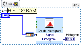
I need to draw the histogram of the system to check the shape of the distribution
I have the vision of labview
help me draw
I thank you in advace
concerning
Mathematics-> probability and statistics, below a histogram express vi that will help you.
Tags: NI Software
Similar Questions
-
How to generate the random password policy password knowing resources
Hello
Any body tell me how to generate the random password policy password knowing the purpose of resource in OIM11g
Kind regards
Mireille NayanHi Pascal,.
You can try the below code snippet:
UserRepository your = new DBUserRepository();
UserInfo user = your.getUserInfo (take);
ResourceRepository rrepo = new ResourceDBRepository();
Resource = rrepo.findResource (resourceName);
By PasswordPolicyAssignmentsRepository = new PasswordPolicyAssignmentsDBRepository();
PasswordPolicyRepository ppr = new DBPasswordPolicyRepository();
The list of passwordPolicyAssignments = par.getPasswordPolicyAssigments (resource);
PasswordPolicy passwordPolicy;
PasswordPolicyAssignment passwordPolicyAssignment = passwordPolicyAssignments.get (0) (PasswordPolicyAssignment);
If (isApplicable (passwordPolicyAssignment, {getMappedAttributes (userInfo.getAttributes ())})})
passwordPolicy = ppr.find (passwordPolicyAssignment.getPasswordPolicyID ());
}
RPG RandomPasswordGeneratorImpl = new RandomPasswordGeneratorImpl();
password = rpg.generatePassword (userInfo, passwordPolicy);Kind regards
GYAN -
The best way to draw the difference of phase vs. time of two signals
I have three channels (time, force, displacement) of approximately 1 000 seconds of a sinusoidal test load test data (sampling rate was 100 Hz). I would draw the difference in phase between the force and displacement (perhaps using a second window 30) according to time. I tried using a few different analysis functions, but I get what looks like random noise (phase difference between force and displacement is very small and the difference in amplitude is very fantastic - 4 orders of magnitude). Any suggestion would be appreciated! -Jim
Hi Jim,.
The phase channel resulting, that you get with the function FFT DIAdem is in the frequency domain. If you select a channel data and time in the FFT dialog box, you will get a frequency channel that results as well as the Phase channel resulting. If you select only a weather channel of waveform data in the FFT dialog box, you will get a Phase of waveform frequency channel resulting.
Brad Turpin
Tiara Product Support Engineer
National Instruments
-
Unable to draw the table 1 d with a cluster of 2 items on a XY Chart
I am unable to draw a table 1 d with a cluster of 2 items on a XY Chart. The data displayed at the entrance in the graph, but nothing is drawn. I'm trying to draw a line connecting each point generated.
You need a registry change on the inside of loops as well.
But beyond that, you create too complicated a structure. You create several plots of 1 point and not a single multipoint parcel.
See attachment for the change that works.
-
Draw the last set of data (1000 samples) in a loop
Hi, I read a waveform data continuously, but I would capture and draw the last data set after my stop. As shown in the picture of attacehd, when the condition is true I acquire data. The number of samples per read is 1000, and as you can see I used a shift register to store data. What I'd like to see where the loop stops is the last 1000 samples but when I acquire real-time data I get a random sample number when the loop stops. sometimes 90 samples, sometimes 950 samples etc... could you please let me know how can I get the last 1000 samples acquired in this loop
I even used DAQmx buffer for data but I can not get the last 1000 samples
Thank you
If your task has a number of points to buy, I don't see how you could have a number UN predictable and random points in the buffer. The task should stop after having acquired the points of "N" and then say it's done.
What do you mean by "stop tripping? You only have a 'start' trigger and it is not available for points once the task has been involved. If you want the last 1000 points of the points "samples per channel", the last reading should return those. I've never used the property "Done" before. Count your samples read instead and stop once you have what you wanted.
-
How are derived from the random bits for new AESKey()?
I was not able to find any documentation on how the random key is generated. There has been discussions on various security forums recently on the use of random number generators nickname (PRNG).
I would like confirmation that the random bits for new AESKey() come from cryptographically safe pounds (like net.rim.device.api.crypto.RandomSource?).
Random data used in the constructor of AESKey() comes from net.rim.device.api.crypto.RandomSource.
-
Layer option in the Random fill script Photoshop CS6
When you use the random fill Photoshop CS6 script, you can use varies depending on the models and colors.
To randomize the photo, you generate the image when you use random fill.
I've used the script to randomize patterns and colors, if you use random fill.
I want to know is can you add a layer option in the Random fill script, which allows you to manipulate the model and color of the layers that would be generated.
But in saying that, you would be talking about perhaps hundreds of layers at least.
Is it possible to add this option to the random fill script type in Photoshop CS6Layer option in the Random fill script Photoshop CS6
N ° when you run the script to random fill, you can only have one setting at a time, one model at a time and one layer at a time. I created a user interface for the script when CS6 is released which allows to break down the filling in different layers, so that you can change the template, but my script does not change the settings. You can see my script here:
-
Realistic of the random movements of multiple MovieClips
Hi here is my code:
30 images/s
var human = 30;
hSpeed var = 4;
for (i=0; i<humans; i++) {
     //attach movieclip with name "human"
     //give it a random x y position (there are now 30 scattered human MCs)
     _root["human"+i].onEnterFrame = function() {
          this._x += random(hSpeed); //Here is the 'random' movement of the Movieclips
          this._x -= random(hSpeed);
          this._y += random(hSpeed);
          this._y -= random(hSpeed);
               //some more code
     }
}
Makes the jitter movieclips on, humans don't do that, I can't find a way to make their random movement still smooth, moving in a random direction for a few seconds (preferably a random amout of seconds), then to change direction - I found a way to do it but it does not work on individuals It works on all 30 movieclips, which means that all move in the same direction.
Don't forget that the movement must be random for each individual movieclip, not all move in the same direction.
Does anyone know how? Thank you
If you want to maintain the movement in a random direction for some time, then you're probably better using code interpolation. Generate interpolations for each object that moves them from their current position to some random in some random delays. And have a listener that determines when the Tween is complete so that a new Tween is engaged with the new direction and speed (time).
-
where can I find the chassis for the import file in MAX to draw the circuit diagram before you buy
where can I find the chassis for the import file in MAX to draw the circuit diagram before you buy
chassis: NI SMU-1078
ini file to import into MAX
See attachment
THX
Hi again Koen,
Unfortunately, you can't simulate a complete PXI system, so we do not have the ability to simulate a PXI controller unit. The simulation, you can do is to set up the cards you want to use in you.
concerning
Lars -
Draw the rectangle to the intensity chart (position where clicked)
I am able to extract the coordinates using the mouse down and mouse to the top of the structure of the event, but unable to draw the rectangle at the specified position. I get the coordinates to the mouse down and mouse up to the event within these limits. I want to draw a rectangle in the position coordinates, but unable to do so.
One last thing, since you use the Rectangle to draw, you need to deal with cases where the rectangle is not drawn from top left to bottom right. Please make sure that the minimum value X goes to the entrance on the LEFT and the minimum value of go at the TOP of the terminal of the vi entrance Rectangle rect. Use the Max & Min function from the palette of comparison for that.
Ben64
-
Is it possible to draw the same color for each curve automatically
Hello
Is it possible to draw the same color for each curve automatically. I use graphic XY basis with data set.
Lol you'll either need to set the properties through the dialog box. Or use the nodes property of the graph to adjust the Active plot and then set the color of the plot. This can be done in a loop For.

-
How to draw the lines automatically
In LabVIEW I must draw a line automatically (both vertically and horizontally) the user will define the vertical and horizontal number lines.
Is this possible with LabVIEW
 Thanks in advance
You move to the point of departure of the line using "move the pen", and then draw the line using "draw the line".
Repeat for each line. (using for example a for loop and autoindexing on positions).
-
Hi all
It is perhaps an easy question as I'm new to Multisim, however I cannot define the word to respond to an external trigger generator. I'm defining the word meter generator, by selecting external to the source of relaxation and connect a clock of 10 kHz on the PIN in the generator T. While I expect to see impulses that occur with my trigger, instead I see it always send data to whatever the internal frequency is no matter my trigger.
I tried the digital clock and the sources of voltage pulse without result.
I use NI Multisim 12.0 Student Edition version 12.0.0 (12.0.592).
I'm doing something wrong, or is this a bug?
Hi MHawn,
The word generator can have an external trigger, but the clock frequency is always defined internally. The speed with which the pulses are generated are based on the internal clock frequency. The switch only controls the impulse triggering. As a test, try to do the same clock frequency clock and relaxation. Note that it is changing over time.
I hope this helps.
-
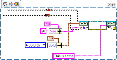
How to set the size of text with the report generator
Hello.
I'm trying to set the size of the text with the report generator, but I find that I can't do this. Here is an example of the code that I use. Can someone tell me what I'm doing wrong please?
Thank you, Alec
I was generation from a word template.
I hacked my version of the Toolbox to give me maunal indicator control "model? He had obtained his permenatly self stuck on "T". I exposed this flag outside the API, so I can control under certain weather conditions I may or may not use the model police.
Does anyone know how to use this toolkit, or I did the right thing?
Cheers, Alec
-
date of reading of hurt to excel using the report generator tool kit
Hello
Im trying to read a date from an excel worksheet by using the report generator tool. I talked about this http://digital.ni.com/public.nsf/allkb/01B026BEB54E3414862571B600618827 KB and it works... kind of.My dates are all read next 4 years and 1 day. Can't really understand why?
Any ideas would be appreciated!
Thank you
DavidThe format of the time in LabVIEW is distinguished by the time format in Excel. If you simply convert the timestamp cluster double
and paste that data into Excel, it won't make sense. This is because the Excel format is based on the number of days
Since January 1, 1900. The time of LabVIEW is based on the number of seconds elapsed since January 1, 1904. Converts this vi
LabVIEW to Excel time time. reverses the logic of switch from excel to labview
Maybe you are looking for
-
What is required to use a headset Logitech h110 with a Mac Mini?
I plugged in two different Logitech h110 helmets to the Mac mini. One of them is brand new from its packaging. Nor, we record the entry levels of the microphone of the headset, as indicated on the screen Preferences sound. Other applications are also
-
Unable to get the restore to work - Satellite 1410 disc
I have a Toshiba Satellite 1410. During a restore of system with restore disks, I forgot to plug it. During the windows set up (this screen where you put in your country and all that) the battery has flat that I plug! I tried to throw the disc again,
-
I have a problem with Windows XP to display upward as not authentic.
I have xp pro and use it for years, I now get a legal copy not on my screen. I went in what I thought was the microsoft support and they tried to charge me $250.00 to fix my problems according to a scan. It was really omnitech support. Can anyone hel
-
Licensed image by mistake and Photoshop files download
Hi, I have authorized image by mistake. File #87064689.I am trying to download the Photoshop #108422278 Preview file but can't. A box pop up said a mistake. Help, please. Thank you.
-
Become Oracle fusion middleware DBA
HelloI want to know how to become a fusion middleware dba currently I work as oracle apps dba.Concerning