Connect an SSI absolute encoder to a DAQ card
Hello, everyone
I try to connect four encoders of DAQ cards. Two of them are in quadrature encoders and the rest two absolute encoders. I'm guessing that connects the two quadrature encoders to both timers/counters on the card. But what of the SSI absolute encoders? Anyone can give a clue? Thank you very much.
Either way, I am using PCI-6251 and xPC Target.
Pengfei
Hi Pengfei,
If you do not use our driver so I don't know if this is supported, but here's how I would do it using DAQmx...
According to the features of calendar defined page 10 specifications page, 500 ns is the minimum period for almost all relevant parameters:
Period of the CLK line semi
Time between the CSn and the first edge of the clock
The CSn pulse width
Well, it makes sense of the clock of your 2 MHz. You need produce waveforms of the following two, each cycle would be clock to 18 bits of data (12-bit encoder and 6 status bits). The total duration of the cycle ends up being long 38 samples and would take 19 microseconds to execute (if updated to 2 MHz).
CSn 1 0 0 0 0 0 0 0 0 0 0 0 0 0 0 0 0 0 0 0 0 0 0 0 0 0 0 0 0 0 0 0 0 0 0 0 0 0
CLK 1 1 0 1 0 1 0 1 0 1 0 1 0 1 0 1 0 1 0 1 0 1 0 1 0 1 0 1 0 1 0 1 0 1 0 1 0 1
The actual binary data to write to the card depends on what lines you use. For example, if you use p0.0 to CSn and p0.1 for CLK, table you would need to write would be the following:
3 2 0 2 0 2 0 2 0 2 0 2 0 2 0 2 0 2 0 2 0 2 0 2 0 2 0 2 0 2 0 2 0 2 0 2 0 2
The bits of the U8 number correspond to the 8 rows on the port.
You will need an example of clock for your task source. I suggest to use Freq Out on the 6251. In DAQmx, it is programmed in the same way as a meter output. You would set this up as a continuous meter to 2 MHz output. Indicate on your task to use ' / Dev1/FrequencyOutput "as the sample clock source (not necessarily Dev1, but regardless of the name of your device).
You would physically signal port thread 0 CLK in PFI lines and use it to sample a DI task so that you can read back your data. You can enjoy on the falling edge of the CLK to allow 500 ns for the value to be set (the maximum duration of your sheet is 394 ns). The only drawback to this is that you are not sampling the parity bit, but apparently not that it is a problem unless you plan to use it.
Once you get the bits, you must translate that into an actual position. When you call DAQmx Read, you will have an array of values. The first value of each cycle is a disposable (look at the waveform to see why). The next 12 items of any cycle would be the 12 data bits, next 5 bits of State. As I mentioned earlier, the parity bit would not be sampled because of the decision of the sample on the falling clock edge (again, you can refer to the waveform to see why this is the case).
You'll want to convert the 12 data bits of the table in a single 12-bit integer, then multiply by (360.0 / 4096) to get the position in degrees. I don't know what development environment you use, but this type of data manipulation must be achievable. For example, LabVIEW has a Boolean array of numbers feature that would be very helpful here.
I hope that helps!
Best regards
Tags: NI Hardware
Similar Questions
-
How to connect a simulation on the design of controllers to DAQ card?
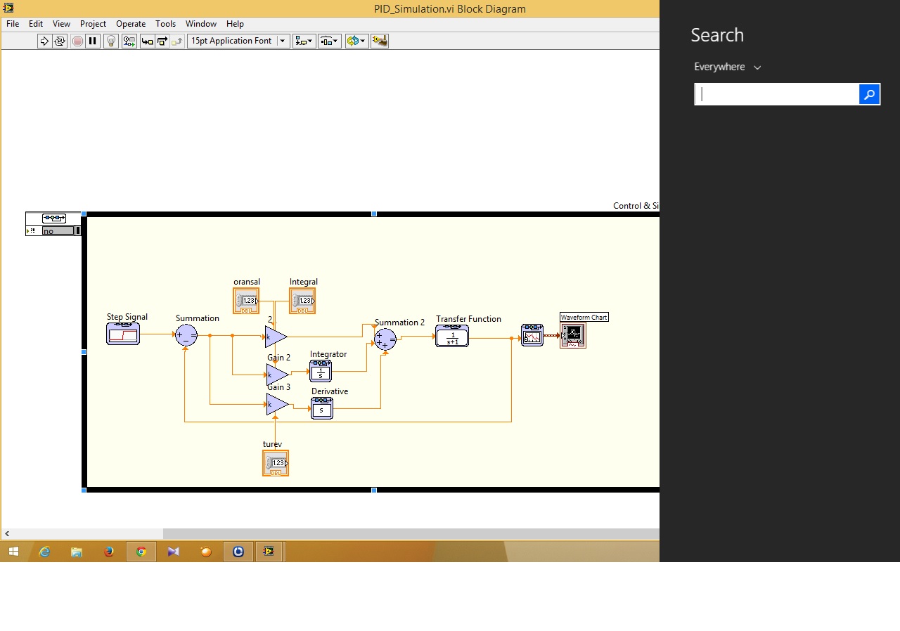
Hi guys... I have problems about control and design on the way to the simulation I just do simulation PID and I can not to connect to the path of the simulation DAQ card in the control design (function)... can someone help me how to connect that?
Ayubi,
First of all, remember that the control and the Simulation has a PID in the Palette "control and Simulation > Controllers.
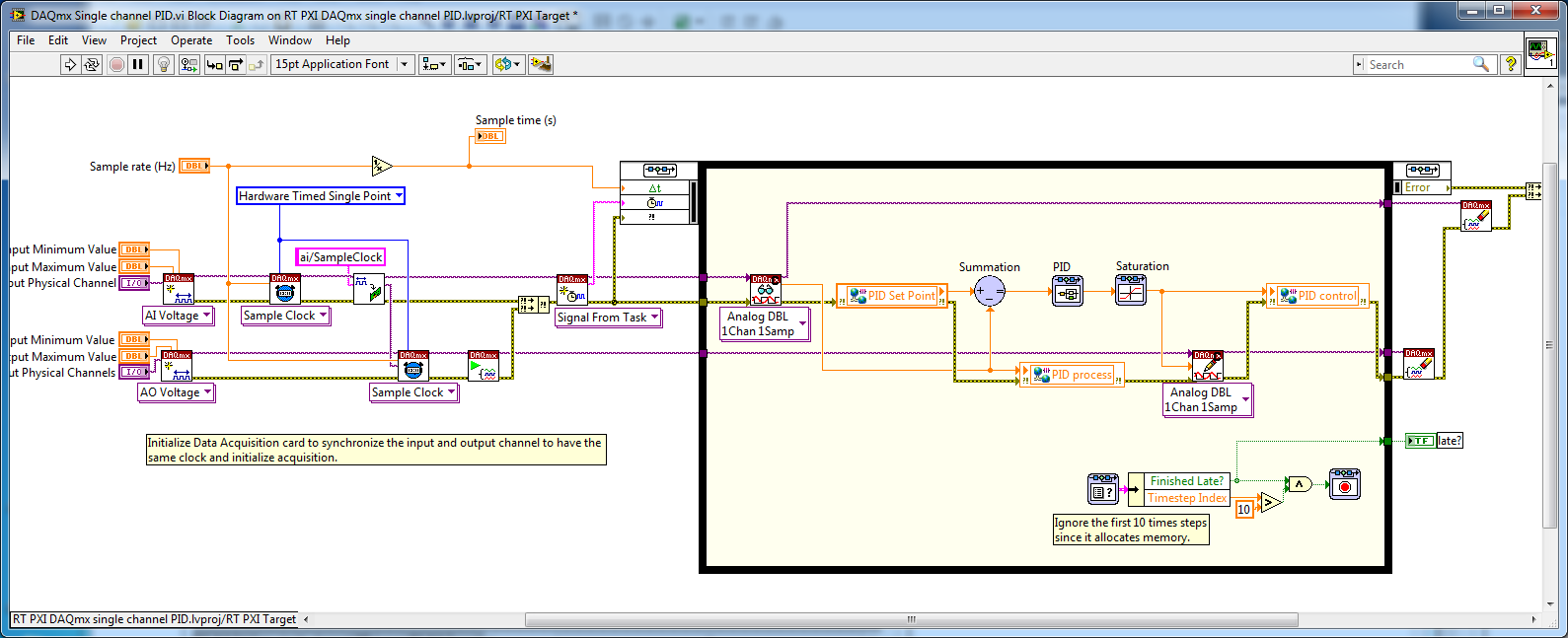
Then, to connect to a data acquisition card, you must use the DAQmx interface is there to connect. In general, National Instruments recommends allows you to deploy a controller a real-time system, but most likely your Windows computer should be good enough for your application. Please see the example of the expedition (in 2013):
C:\Program Files (x 86) \National Instruments\LabVIEW 2013\examples\Control and Simulation\Simulation\Real - time\DAQmx\RT PXI DAQmx single channel PID.lvproj
If you don't have a LabVIEW Real - Time (RT), you can simply open the VI:
C:\Program Files (x 86) \National Instruments\LabVIEW 2013\examples\Control and Simulation\Simulation\Real-time\DAQmx\DAQmx single channel PID.vi
Remove the shared Variables in the code and he would be executed on a computer with a DAQ card.
-
Entry of absolute encoder PWM w / 6008
Hi, I'm quite new to the DAQ world so please be easy on me.
Well basically, I have acquired a free 6008 and want to use it to track the absolute deviation of angle of a device I have.
My scope involves the use of a labtab (USB only), as well as a range of measurement 0-90 degrees with an accuracy of 1 degree at most.
So I came to the conclusion that I have to get an absolute encoder.
Watching the encoders and their respective exits, I found the following: SSI, Linear Voltage (0-5 Volts) and PWM
I have falling SSI my list because it seems a PCI data acquisition card is a requirement, and the linear voltage is all simply not precise enough, because the encoder outputs (0.056 volt/deg) and the 6008 can be read only with accuracy intervals (0,138 volt). Which means (2.484 degree/interval), I think.
in any case, the last style of output that I found was the PWM signal.
The encoder http://usdigital.com/products/encoders/absolute/rotary/shaft/ma3/
If I have good outings (at intervals micro-sec 1026), where the duration of the pulse is the position of the encoder. (1026 counties/revolution).
So I guess I have to be able to read the pulse of the order (1 micro-sec) for (1 head).
My question is whether or not the 6008 is able to acquire the data for my use in LabView.
Counter the 6008 says its able to detect more than (0,1 micro-sec) pulses.
Does this mean the 6008 so capable of doing the job?
Any help is grateful, as I have very little experience with LabView or DAQ instruments.
Thank you.
It is a limitation just to the meter of a USB-6008. What you describe with 2 counters is actually very close to what we do for measures high frequency on our complete recommended counters. The pulse actually measure that requires only one meter on our E-series, M-Series devices, meter Timer and X-series.
In regards to the analogue output of the absolute encoder, I think you should be ok with the resolution. The output of the encoder is 0 to 5V. The typical accuracy on the 6008 for this interval is 4.28mV for differential connections. Step for each degree size is 5 /(2^10) = 4.88mV. Thus, it seems that you will be able to get a precision less than 1 degree.
If you need better accuracy or would prefer to make the PWM output type, I would look at our M-Series USB for a portable data acquisition solution. Let me know if you would and I'll give you a few recommendations.
Regads,
Paul C.
-
Read an absolute encoder in cRIO 9076
Hello
I try to use cRIO 9076 and NI 9401 to read an absolute encoder (http://www.gpi-encoders.com/PDF/A58.pdf). I hope that it is possible. Please can someone advise if there are any example or a tutorial that explains how I can deal with the digital input data to get an output of numeric position? Thank you.
Hello:
Are you using the A58-12 encoder? (It's the only one that looks like it will work with the 9401). If so, it returns data using the series SSI Protocol.
You will need set up an output clock and the input of the 9401 SSI data line. For the reading of the data, there is an example of FPGA SSI on the community related to this knowledge base Article.
Hope that helps out!
-
selection of the daq card to get the angular position of 6 motors with encoder
can you suggest me best daq card to use 6 positions of engines as outputs using encoders attached to the engines. I'll use single window for each engine. Or what can I use a single window for all the coders of engines?
Hello Prabhakar7117,
You need a counter for each encoder. Because you are going to use 6 encoders, you should get a DAQ hardware with 6 or more counters. Take a look at the PCI-6624 or PCI-6602. Another option would be a CompactDAQ chassis with modules that are able to access counters. Take a look at them.
KB which cDAQ Modules can be used to access the counters of the shipped?
Best regards
Alina M
-
Ghost NI USB DAQ card readings
Hello
I have a question about the behavior of the NI USB-6218 data acquisition card. Right now I use Labview to take several current readings of different channels to HAVE it. I use resistors 250 ohms for each channel just as the instructions say to make the current readings. I had an incident where he has been disconnected one end of a resistance at the entrance to the port. I expected to see the reading go to zero, but instead, he began to piggback off the coast of reading one another channel give me a kind of 'reading ghost' because there was essentially no current crosses. Playback of disconnected channel displayed the current reading of the canal connected even while values went upwards or downwards. Can someone explain why the DAQ card would do that? and anyway to avoid this to happen?
Thank you.
A data acquisition uses a multiplexer to send a signal to the ADC. Due to having only 1 ADC, you will get this effect if the ability has no way to bleed. There is no way to avoid this if you disconnect the side DAQ, leaving the open input channel.
You could try adding in some amplifiers specially designed for the shunts of currents. I have used TSC103IPTwith success. This amplifier gives you a single output is completed. But I don't know what will happen with these if you disconnect one side of the resistance of the amplifier.
-
How display the waveform acquired DAQ card separately in wavefrom graphic
I NI 9239 DAQ card and it has four channels. I need to create a user interface graphic labview in which I need to display all the forms of four wave separately. If I select all four channels of the daq assistant and connect the waveform table all four waves are coming to overlap... I need separately for the treatment... what should I do?
Thank you and best regards...
Try this
-
Acquisition of data using the DAQ card
Hello everyone
I need assistance with the acquisition of data of the generator of signals through DAQ cards. I plugged the signal to the SCB-68 generator where the analog inputs of the generator are connected to AI CH5 and AIGRND of the Terminal Board. Then the output of the block is connected to the DAQ card. The maximum sampling frequency of the card is of 250 kech. / s. The problem is for reason that I am not able to see the waveform on the labview. I looked at other examples to find the problem, I am, but I am not able to understand this. I want to be able to choose the sampling frequency. I attatched my code as an attatchment for you all to help me know what the problem is. Any suggestions will be appreciated.
There is no task! You have not specified any hardware (i.e. your data acquisition card) anywhere.
Here's a suggestion. MAX aperture. Find your DAQ hardware. Open a Test Panel. Implement a continuous sample of N Points to some sampling rate. Press Run and convince yourself that you get the data.
Now, while remaining in MAX, to create a task, using the same settings. Call for example something sensible ("MyFirstDAQTask" is not a good reputation).
Now, go back to your code. Eliminate the first two functions DAQmx. Wire a constant task to the DAQmx Start feature. See the little triangle down? Click it, and it should show you the tasks he 'sees', the only one should be the task that you created in MAX.
Note that 'Samples Visible' is now 'hard coded' in the task. To get its value back out, you need to put a property node Timing DAQmx after the task start and pull on the quantity of the sample, samples per channel (which, for reasons that escape me, is a Dbl, you need to convert to an I32 before importing it into the while loop).
Bob Schor
P.S. Thank you to join your code.
-
Many DAQ cards synchronize hardware for PXI
I recently went through the process of getting several PCI DAQ cards in a computer and synchronize them together using a RTSI cable. I just bought two similar cards in PXI. I had to add a RTSI cable DAQmx devices manually in the measurement and automation software, and connect the cable with the PCI cards. I want to just make sure that I don't have to do the same with the PXI cards because there is no necessary RTSI cable for PXI.
Thanks for any help,
Mike
The PXI chassis has backplane triggering and clock lines so that you don't need the RTSI cable.
-
Tecra 8100, connection to the internet via a Vodafone data card
I'm having extreme difficulties, the tecra 8100 recognizes the card etc etc, but will not let me create a profile and when I try to connect to the internet tells me that the card cannot be found... Gray goes with it - have disabled the internal modem and told my system to use the card... Help
Hello
Do you have software for this card? If so, you should try to re - install the software.
But in my opinion you should contact Vodafone support because they have more experience with own products.Sorry
Good bye
-
Error-200284 when using two daq cards
I have an application written in Visual C++ that reads data out of a data capture with success card. However, now we want to add a second DAQ card, so we can increase the number of input channels. However, I have trouble getting the second card works fine. He continues to give the 200284 whenever I try to read the input data. I tried playing with the two loops in the same thread and with them in threads separated without result. Any ideas on what could happen?
Thank you!
Hello Kaladin,
I'll take a look at the link below to see the cause of the error, but also some common things suggested to try.
http://digital.NI.com/public.nsf/allkb/FEF778AD990D5BD886256DD700770103
Best wishes!
-
MAX with replication DAQ cards
Hello
Hope someone could shed some light on this

Its a long time since I've used Labview & MAX and am a little rusty right now.
I'm trying to upgrade an old data acquisition system to a newer version.
This is because originally one full working backup system was necessary, but because the old DAQ cards are obsolete,
a simple update was necessary.
Old system:
LabVIEW 7.1
MAX 3.1.1
Data acquisition card: PCI-6023E
New system:
LabVIEW 7.1
MAX 5.0
Data acquisition card: PCI-6220
There is no change in the Labview application.
In the new 5.0 MAX.
I'm trying migrate/replicate all virtual channels & settings of the old system.
I managed to set up a new configuration using file for the acquisition of data from the old system.
This resulted in the creation of chains of virtual of NOR-DAQ traditional under the District of data, which is what I wanted.
But the problem is, all the channels received a red cross.
Clicking on properties of the individual chain shows that no device is selected in the hardware section. There is none to choose from.
Under devices & Interfaces,.
The new card is correctly installed and running.
Appears as > NI PCI-6220 'Dev 1.
How can I make this device available in virtue Traditional NOR-DAQ virtual channels in the data area?
Is it because the new MAX/data acquisition card requires the method task NOR-DAQmx to create virtual ways?
I want to migrate channels instead of recreating that there are a fair few and each with their own settings.
In the old system.
Under devices & Interfaces,.
That's what it shows:
-Devices of NOR-DAQ traditional
PCI-6023E (1 device)-OR-DAQmx devices
-PCI-6023E: "Dev 1.The device is recognized under the District of data - Trad VC through NOR-DAQmx devices.
I can attach a screenshot for systems if it would help at all.
Thanks in advance!
-Ram of Aust
Bad news... Your most recent 6220 is a M-series it is * not * supported by NOR-traditional DAQ. This is why it does not appear as an option under the traditional OR-DAQ driver. To use the most recent data acq card, you * must * swtich above DAQmx.
Your old 6023E Board should be accompanied by one or the other pilot (but never both at the same time), so it may be be jointly installed a print while you set on the (tedious) company to recreate channels for your new Board in DAQmx.
-Kevin P
-
Synchronization of several high at different frequencies of sampling DAQ cards.
I'm having sync problems 3 high DAQ cards with different sampling frequencies. I use 2 cards PXI-6259 nec 10,000s samples and 1 PXI-6221 Board to interface for my SCXI modules in 10 samples/second. The problem that I discovered is the time related with the waveforms of the NI PXI-6221. When I run the code on a development computer using virtual devices in MAX, it works as expected. When I run the same code on real hardware, the stopwatch turns approximately 25 X faster than normal. I enclose the code and the config that I use.
Any ideas?
Hi NGNN CAD.
First of all, let me say that your code is very nice!
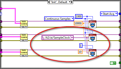
The problem is that you are using the fast sample for the device that is supposed to be slow clock:
Even if you specify the rate as 10 Hz, the clock itself is still at 10 kHz (by specifying the right rate allows the DAQmx driver determine the size of buffer etc and don't actually change your external sample clock speed - however, it changes the rate of the simulated device).
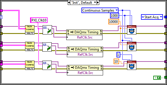
My recommendation to synchronize devices would use the built-in PLL and lock to the reference clock 10 MHz of your PXI chassis. Your devices would always share a trigger to start, but each would generate its own sample clock based on its time base that is locked to 10 MHz reference.
The code should look like this:
I hope this helps, let me know if you have any questions!
Best regards
-
How to give input to the DAQ card three times
Hi all...
How to assign three channels of entry (as Dev1/ai0, Dev1/ai1 and ai2/Dev1) DAQ card at the same time?
Rd,
Ganesh
BMETTENT wrote:
Hi all...
How to assign three channels of entry (as Dev1/ai0, Dev1/ai1 and ai2/Dev1) DAQ card at the same time?
Rd,
Ganesh
Use Dev1 / ai0:2?
-
Data acquisition in LabView for other suppliers DAQ cards that NEITHER
Hello
I am a beginner in LabView programming. I have a 32 channels base PCI card DAQ (i.e. PCI-1602 of the manufacturer, ICPDAS) and I want it to interface with Labview 8.5.
So how cards DAQ in Labview 8.5, which are manufactured by other suppliers that NEITHER? Should I DAQmx (or some other driver) for that?
What are the other drivers/components required to access of data PCI-1602 (device) of LabView 8.5 acquisition card?
(1602-PCI card driver are installed in my win XP and dispalyed in Device Manager).
Please provide some tutorial above mentioned the problem to interface.
Please guide me in this regard. Thank you
Waqar123 wrote:
Hello
I am a beginner in LabView programming. I have a 32 channels base PCI card DAQ (i.e. PCI-1602 of the manufacturer, ICPDAS) and I want it to interface with Labview 8.5.
So how cards DAQ in Labview 8.5, which are manufactured by other suppliers that NEITHER? Should I DAQmx (or some other driver) for that? You will need the drivers from the manufacturer, of the Board of Directors. In your case, "ICPDAS.
What are the other drivers/components required to access of data PCI-1602 (device) of LabView 8.5 acquisition card? Same as above.
(1602-PCI card driver are installed in my win XP and dispalyed in Device Manager). Ok. Then take you care of my 2 answers above.
Please provide some tutorial above mentioned the problem to interface. To learn more about LabVIEW, I suggest that you try to watch some of these tutorials.
Please guide me in this regard. Thank you
According to what you do with the DAQ cards, they can do the job however, from experience, there are some functions that I could achieve with the cards NOR that I couldn't with 3rd-party maufacturers. This does not mean that this is your case. However, it is worth noting that it took me a while to understand why the code has worked with a single data acquisition card (NOR) but not another (Non-OR).
The drivers that you have installed may or may not include examples and code in VI. They may be DLL. If this is the case, you can write LabVIEW "Wrappers" around these functions, as it will simplify your life. If the drivers are in the form of DLLs, and there are no examples of LabvIEW or available VI, you must read on node library function call.
R
Maybe you are looking for
-
How can I remove the automatic log on some sites
I allowed firefox to remember the user name and passwords on some pages. How to 'remember the United Nations' these passwords?
-
Why can I not see my gmail mailboxes in mail in El Capitan?
I do not see my gmail mailboxes in mail
-
Xbox controller will not adapter PC connect
I plugged the adapter (he currently holds a green continuously), downloaded all the latest drivers. When I try to connect wirelessly to the adapter ring on the controller, the controller starts to turn and then suddenly stops, continue to Flash a ful
-
How can I capture video on my hp pavilion p6-2190ea
How can I capture video on my hp pavilion p6-2190ea
-
While a hp ink printerwon can't print
printer recognizes the printer is ready, but will not complete the task, how can I find out why?