example of k-means algorithm
can any give me an example to find the attribute class label using k-means algorithm, or please tell me where I can find it.by thanking everyone.
You can use the k-means algorithm and change the calculation of the distance in mode (frequency). I found the code for average k in http://people.revoledu.com/kardi/tutorial/kMean/download.htm
Tags: Business Intelligence
Similar Questions
-
identify the initial centres of the k-means algorithm in the MDGS
I need to identify myself to the k-means algorithm initial centers in the MDGS. It's because of are best clustering. How can I do?
tanksODM-k-means does not randomly initialized centres. Instead, she added bunches gradually to regions of space according to needs. You can provide your own initialization.
I hope this helps.Boriana
-
What cluster algorithm should be used?
I have several items of data in tabular form with all of the digital values under each attribute. I want to cluster data objects (or) I want to find the attribute class for each cluster labled.
Please tell me, if I use k-means algorithm or should I use any other algorithm.the most well known of clustering are k-means algorithm that completely agree with objects and hierarchical. You will find tutorials for two clusters in http://people.revoledu.com/kardi/tutorial/index.html
-
Play my music on apple machines
I would like to power access/play my music, currently stored on my computer, on all my Apple machines. What is the best way to do it?
There are many ways, depending on your exact hardware configuration and needs. For example, do you mean away from home? There are library sharing and sharing at home and game and Apple iTunes music and family sharing and sharing libraries between computers and media between computers only sharing and...
-
Satellite U400-15E - cannot start new USB HDD
Hello.
Recently a bought a WD My Book external with 3TeraByte to use with my Satellite U400-15E. I can use inside Windows 7 Ultimate without problem. But if I try to boot from it (by pressing the F12 key), the BIOS does not even see the drive.
Is it because Toshiba does not use Unified Extensible Firmware Interface (UEFI)? UEFI BIOS can overcome the limitation of 2.19 to in computers today easily, as explained in the following Western Digital document:
[http://www.wdc.com/wdproducts/library/Flyer/ENG/2579-771501.pdf]This would allow me to use my new external drive to store an image Ghost drive HARD internal of my Toshiba for example. I mean 3 TB and more capacity is a reality today. When Toshiba updates their UEFI BIOS support?
Material used:
Toshiba Satellite U400-15E (BIOS v5.00 10/26/2010)
Western Digital My Book Essential 3TeraByte - Firmware v1.014 (USB 3.0 interface)
MS Windows 7 Ultimate - 32 bit versionThank you
Hello
Satellite U400 supports devices to boot according to the user manual:
USB FLOPPY DRIVE
HARD drive primary school
Optical devices
Network (LAN)If the USB drives are not supported.
But you're absolutely right Re: 3 to and a larger capacity is reality today, but Satellite U400 is older model laptop and not newer ;)
-
A BIOS update affect the recovery of a machine?
I am about to use the disc of recovery for the first time and have any questions about the procedure.
* An updated BIOS would affect the recovery process? *
Since I use my laptop, I installed the latest BIOS for it and I was wondering if the recovery of product would be assigned to all the by - and if so, no matter who has no idea where to get BIOS orignial, or how the 'dismantling' of the BIOS that I noticed that the BIOS back it self up when updated with a newer version.
Taking advantage of the grace.
Yes, all preinstalled applications are part of the recovery image.
The image contains the operating system Windows, Toshiba drivers, tools and additional software such as Norton Antivirus for example.
This means that these additional software would be installed too by using the recovery CD.Best regards
-
Number of cycles in the target FPGA VI
Hello to everyone.
I'm working on a project where I use sb RIO 9636. I subtract a number of past and present of the encoder pulses. Here, I have attached VI that I use as target VI. When I use simulated I/O lets say that the program works correctly. When I compile VI on sbRIO I noticed that the LED indicator named x = y? never flashes (even if she flashes simulation). Also, when I put indicaton on the number of cycles of control, counting starts from a few very very valuable.
Could someone help me?
Thanks in advance.
Hi Chupka993,
I suspect that part of the behavior of the that you describe, is that when you change the clock of the loop, you change the speed at which the loop works. As GerdW said, this loop timer setting gives your code a rate at which it should run. For example, defining 1ms means that your code inside this loop executes once per millisecond, or 1000 Hz. ticks would work similarly, but I think the timescale ticks of the FPGA clock which is generally 40 MHz on our devices.
When you have the timer set to 1 millisecond loop, the code in the loop executes 1,000 times per second, and your iteration count would be 1000 times before update output, which means that your code runs a full 1000 iterations once per second. If you change the clock of the loop of 2 milliseconds, the loop will run 500 times a second sense that your 1000 iterations would take 2 seconds to run. I think that the behavior you're seeing is because the iterations are produce faster that you intend.
You need to understand exactly how much time it should take your loop to run 1000 times and then set the timer loop to the appropriate value to achieve this goal.
-
Hi, I have a question about the regular expression: If you look at the attached code you will find two examples. It is an old piece of code, but now I have to fix a bug that was discovered after a few years of use. Task: If the entry is for example C1 - C4, the algorithm needs generate a table of C1, C2, C3, C4. This should work on any digit and letter. Examples: R1 - R5, K569-K799, S2 - S3. This works very well for [letter] [number], but my regex won't work for the case now, I have to solve. If the entry is C1A1-C1A4 the output should be C1A2 C1A1, C1A3, C1A4, but I don't know what should look like the new RegEx so that it still works on [letter] [number] [letter] [number].
You can not only use [0-9] + $ to return only the number of the end of the string?
Regular correspondence Expression.vi will return all the foregoing the final number in 'before the game '.
I'm sorry that I can't look at your code since I don't have a LabVIEW 2011 on my system.
Rob
-
AO HAVE synchronized with the data processing
Hi all
I'm building a pretty simple VI that should work in the following way:
1: acquire the data of two channels of AI with a sampling rate of 2000 Hz
2: process data: some time on average and the scaling of the output of the signal depends on the entry
3: write data to both channels of the AO. (A button control if the output of the AO is either 0, dependent on the entry)
More important is that the delay between real HAVE and AO transformed is reduced to a minimum.
Following several examples I came with the attached VI.
There are two problems:
1: Although the principle of synchronization works without the Subvi data processing in the meantime, integrating the Subvi and all screens
makes a sinusoid of simple test of a function generator with a lot of defects (not being is not smooth). I know all the screens to slow down time of the loop, but those which are essential
for the application. Any suggestions?
2: although it runs, it keeps giving E - 209802, something with the task without name, is not really make sense to me.
Thanks in advance for any help,
Mark
Mark,
I think that only timed material point is appropriate for this application, however, I suspect that you will have questions turning over 10s of Hz on Windows without eventually see such errors that 209802 as the OS itself may decide to suspend your application for a quantity of unpredictable weather. I recommend that you take waveform graph remains out of your IO loop. I would recommend that you reduce your loop to display a little, because she's still going to pull data from the queue and update shows as quickly as possible. I think this logic added to wait a number of elements to be present in the queue before the queue and display of data can be reasonable. If you do this, you'll wait also added 'queue' function in this loop so that you're not the queue to vote and by using too much CPU as possible.
Point single timed material, DAQmx will always return the most recent example. This means that if your loop runs slowly, you lose a few samples. If this is acceptable for your application, then receives the 209802 error may not be important. You can use the DAQmx in time real property property of the knot, '' convert errors late warnings in custody '' to make it a non-fatal condition.
My final suggestion is to determine which parts of your code are taking the most time to execute. If you know where you spend your time, it can direct you to the places where you can optimize and remove some run time. To do this, you can try to remove parts of the logic and see how it affects the rate of the loop, you are able to maintain.
Hope that helps,
Dan
-
Adding values to a table in a State Machine
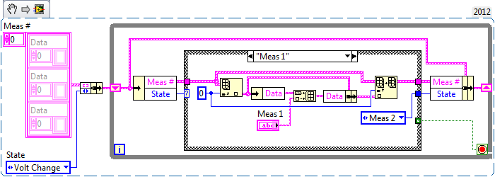
I'm building a VI that control several instruments and then takes data from these measures and applies them to the calculations appropriate to the materials science, such as the resistivity and Seebeck effect. I created a state machine that establishes a level of tension and takes three sets of three different measuring points, using a scanner Keithley 7001 and nanovoltmeter Keithley 2182. I'm now trying to find a way to take action and put them in three separate tables so that I can use them for analysis later. I prefer the tables because there are several screws that can help me to do what I have to do easily (for example, the VI means), but if something works better, I am open for entry.
My simple question: what is the best way to take measurements of the case 1 SOUL, SOUL 2 and 3 soul and store them in three separate tables?
I enclose my VI.
Edit: Just after the announcement, I decided that I will take the structures of sequence holding the sections measure and instead turn them into business within the state machine. I'll post a new VI of the present when I finished.
In this example, I used a structure called soul #. This structure allows each soul to have its own unique array.
The structure is an array of clusters. The cluster contains a string array named Data.
I hope this helps.
-
Is it possible to wait in a queue and a reporter at the same time?
Hello!
I'm trying to implement a model event producer/consumer with queues. The problem is that I have a certain value change events (for example from a slider) I want to make the tail upward; I want only the last value change events to be processed by the loop of consumption. That's because the consumer can spend more time in the execution (sometimes several seconds) and I want to warn all the events of middle slider to be queued up pending because I write them finally to the material. Therefore, a notification utility would be preferable to use a queue here. My question is if it is possible to make the same loop of consumers to wait in the queue, as well as on the warning system at the same time? I will be wiring the VISA session and other data through consumption, if she wants to avoid an extra loop that would wait on the registrant only. Or is there another possible workaround solution?
Thanks in advance.
Kind regards
Anguel
This example has a meaning? It is based on Mark's original proposal.

-
Cursor for display and control time video
Hey community,.
I run a video with the IMAQ / AVI components. To this effect I want to have a timeband as there is one in a normal video player. Time turns and if I click the video on the tape should be at this point in the video. Is it possible to manage that, or do I have to separate the time display and an additional control to reach the point of interest?
In the file there is a small example what I mean. (LabView 2010)
Thanks Philipp
Hi Philip,
You can do this by changing "playback AVI File Example.vi" (see screenshot). I've also attached the VI registered with "to the previous version", I hope it works for you also.
This example uses the function 'IMAQ AVI2 read framework VI' where you can specify the desired image. So you have only control who can change the current framework, which normally is incremented at each iteration of the loop.
Best regards
Christoph
-
cRIO, Webservice (REST) and front panel
Hello
I created a few simple webservice screws for greater application that runs on a cRIO. The webservice screws can be used to send simple commands to the application and give your feedback. So far, I used a LV frontpanel for interaction with the system, but for several reasons, I am looking for another way to do it.
It worked well in the development environment. After deployment webservice screw they have communicated with the application according to the needs and I am able to control the system using simple URL typed in the browser's address bar. Later, I will add static content, but for debugging, it is fine.
The thing is that now I have compiled and deployed the application, and now when I try to open the front panel I get this error message:
"VI requested is broken and cannot be read or controlled."Previously I did not use the Web OR Application Server, so I installed to use the web services. Are there conflicts between a Web application server and remote server Panel? Any suggestions on how to proceed?
I use LV 2012 and NI RIO 12.0
Best regards
Simo
Hi Simo,
If I understand correctly, you have the following configuration:
cRIO with a Web Service of LabVIEW and several Web Service screw
Some ways to debug deployed screws of LabVIEW Web Service are:
You can have the Service of the Web of LabVIEW deployed in debug and debug remote Web Service of LabVIEW desktop.
You can use a tool like factor to make it easier to apply and test your Web Service screw (similar to go to the url in the browser).
You can create LabVIEW screws of office using the Palette of HTTP Client to test the Web Service.
You mentioned the following"I have compiled and deployed the application, and now when I try to open the front panel... "
I'm a bit confused as this front panel you open. For example, do you mean that a LabVIEW project has been opened on the desktop, the Web Service of LabVIEW in the project has been deployed to the target of RT cRIO, and now, when you open the Web Service screw on the desk to look at the front panel, you get an error message?
-
accuracy of digital data from LabVIEW
Hello!
I have a question about the accuracy of data, Labview, is perhaps a silly question, but it drives me crazy.
If I use a digital constant and I put for example 1 (I mean 1E-6), it looks like 1E-6 but I found that it is not really 1E-6, actually if I raise the precision and I use 17 digits, 1E-6-9, 9999999999999996E-7.
Could someone explain to me what is happening for digital data?
Thank you
It is one of the most frequently asked questions ever.
The trick is in how computers represent floating point value. I remember a lot of right answers already given in the forum, but I am not able to find the most comprehensive and clearest.
For example, one of the answers is here.
-
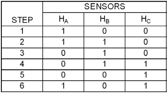
How to create a simulator of hall sensor using NI USB-6221
Hello.
I am creating a hall sensor Simulator using the NI USB-6221 case.
The idea is to have three digital outputs that generates output a digital pulse according to six different stages train.
See the table below.
And it's interesting to have this work in for example 5000 RPM (meaning 2 milliseconds between each stage).
My question is, is it still possible with the NI USB-6221 housing?
I tried to create a simple state machine, leading the outputs according to a predefined table. But it became clear that it is far too slow. The NI USB-6221 uses 10 to 15 ms to generate a numerical value of LabVIEW.
Thanks for any ideas on how to do it.
Looking at the datasheet.
http://sine.NI.com/DS/app/doc/p/ID/DS-10/lang/en
Under the digital I/o, you can see that the digital lines on Port 0 maximum clock frequency is 1 MHz. This means that you can go from a Summit to a minimum once all the 1 micro second. Your hardware is capable.
The software side of things you should realize that to change the digital line from a high to a low that fast, you need to use certain types of calendar that does not have Windows. Windows (and other operating systems) are not deterministic. So instead of being in a loop from one State to the other, put in the buffer of the DAQ one card series of digital States and then specify the DAQ hardware to read at a given speed. Then your synchronization is performed by the hardware, not by your software.
Search for finder example for Digital - output continuous for an example on how to do this.
Maybe you are looking for
-
Firefox has been a problem and crashed
I had this "Firefox has a problem and crashed," started this morning. It overwrites every time when I tried to start it, even with safe mode. I tried to uninstall and reinstall Firefox. But it does not solve the problem. Here is the list of the crush
-
If I open a PDF, Word, Excel, jpeg or ANY type of file it is saved on my desktop (where I put the files to backup). And, this action is done automatically, every time, it's okay that I put in Firefox > Preferences > Applications.
-
Equium L20-198 loses time - about 7 minutes each day
My L20-198 system tray clock loses about 7 minutes each day.I can update manually via the "set Date/time" function right click but must remember to do whenever I start and, as often, I forget quickly become desynchronized of 20-30 minutes. Any ideas
-
Analytical problems C\windows\winsxs\x86_m. 8df276c1fb\AacGenral.dll
McAfee Anti-virus full always stops on the file - C\windows\winsxs\x86_m. 8df276c1fb\AacGenral.dll I find that I have more than a dozen of them in the same folder, all the same s size 2.05 mb, but created on different dates. Do I need them all? Can I
-
external drive suddenly protected by bitlocker
I have just connected my external hard drive to a machine of win8 and was informed that it was protected from bitlocker. I had never heard of bitlocker and therefore have no idea of the key. I then connected the same drive to another, more recent mac