Number of cycles in the target FPGA VI
Hello to everyone.
I'm working on a project where I use sb RIO 9636. I subtract a number of past and present of the encoder pulses. Here, I have attached VI that I use as target VI. When I use simulated I/O lets say that the program works correctly. When I compile VI on sbRIO I noticed that the LED indicator named x = y? never flashes (even if she flashes simulation). Also, when I put indicaton on the number of cycles of control, counting starts from a few very very valuable.
Could someone help me?
Thanks in advance.
Hi Chupka993,
I suspect that part of the behavior of the that you describe, is that when you change the clock of the loop, you change the speed at which the loop works. As GerdW said, this loop timer setting gives your code a rate at which it should run. For example, defining 1ms means that your code inside this loop executes once per millisecond, or 1000 Hz. ticks would work similarly, but I think the timescale ticks of the FPGA clock which is generally 40 MHz on our devices.
When you have the timer set to 1 millisecond loop, the code in the loop executes 1,000 times per second, and your iteration count would be 1000 times before update output, which means that your code runs a full 1000 iterations once per second. If you change the clock of the loop of 2 milliseconds, the loop will run 500 times a second sense that your 1000 iterations would take 2 seconds to run. I think that the behavior you're seeing is because the iterations are produce faster that you intend.
You need to understand exactly how much time it should take your loop to run 1000 times and then set the timer loop to the appropriate value to achieve this goal.
Tags: NI Software
Similar Questions
-
How to use the target FPGA and co. on the same chassis cRIO?
I have a cRIO system consisting of a master chassis 9074 with several modules IO and EtherCAT 9144 slave unit.
I want to run a CIE (see: http://zone.ni.com/devzone/cda/epd/p/id/5333) on the chassis of the master, this uses the analytical engine. At the same time I have to do some very urgent measures if I want to use the Board in hybrid mode, using analysis and FPGA engine at the same time (as described here: http://digital.ni.com/public.nsf/allkb/0DB7FEF37C26AF85862575C400531690.)
But as soon as I add the FPGA target at one of the chassis, the feature of the ice on this chassis stops working. After some research, I found that the CIE can initialize is no longer the modules belonging to the frame that has the target FPGA on it. Error in the method Init of the CIE is: 65700 (indeterminate). This occurs when you try to use "for a more specific class' on the modules configured with a target FPGA on it.
Someone knows what can cause exactly this problem and perhaps provide a solution/work around?
Many thanks in advance.
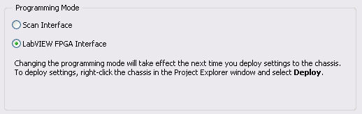
Hybrid mode requires you to have a bitfile compiled running on the FPGA to be able to read the Scan Interface IO Variables. Move the target FPGA at the RT target module will allow Interface of scanning for this module, but the frame will always mode Interface of LabVIEW FPGA.
To get fair access to the scan mode for the frame, right click on the chassis in the project, and choose Properties. Then, modify the Scan Interface programming. If you want to continue using the programming of FPGA and the Scan Interface set (hybrid mode), you will need to compile a bitfile (empty if you do not want programs on the FPGA again or containing your FPGA code). By compiling, the support of the module scan mode for the modules under your RT chassis is compiled in your custom bitfile. Then, on your VI RT, you need to use reference FPGA VI open to your newly compiled VI. Once this VI is deployed and ongoing implementation, you get the data from you are the CIE.
For more information, see this knowledge base article and Reference Interface of Scan CompactRIO and procedures.
-
Number of items in the target to host DMA FIFO
Hello world
I would like to transfer a set of datapoints of an FPGA to a RT-host controller using a fifo DMA. If I use the 'Get number of items to write' function on the FPGA target, can I get the total number of items in the two buffers, or just one on the FPGA target?
(see http://zone.ni.com/reference/en-XX/help/371599H-01/lvfpgaconcepts/fpga_dma_how_it_works/)
markus_a wrote:
If I use the 'Get number of items to write' function on the FPGA target, can I get the total number of items in the two buffers, or just one on the FPGA target?
The FPGA will have no idea how big the DMA is on the side of the host. He can't see his own DMA buffer.
Get the number of items to write just tells you how many items are not used by the DMA (ie the number of items that currently write to the DMA without waiting for items to be offered by the host reading).
-
date and time of transfer to the target fpga
Hello world
Can I transfer the date and time of real time on target fpga in a sbRIO?
Thank you
Hello
You don't know why you would want to try this, can you clarify? You cannot send the timestamp as it is, but according to what you want to do, there will be a solution. This describes how a timestamp is stored in LabVIEW, but you probably want to send/receive something more easy to handle on FPGA.
Michael.
-
In the target FPGA read/write control function?
Hi people,
I learn a lot from the sample project FPGA, including how you can easily retrieve and set controls and indicators in an FPGA using the read/write control function running in an RT target.
However, I can't find a way to do something similar in a FPGA target. I've been down this road before - that is, trying to move the data in/out a looping VI FPGA (void) to a (parent) FPGA VI - where my memory points to reach what I needed use.
So I was happy to see the palette FPGA enabled me to drop the control functions to read/write on a FPGA vi target. But alas there where tons of errors (not compatible son for target, etc.) and I guess now it's not possible.
So, just to be sure, I'm not missing something, is there something like control functions to read/write to use in an FPGA for read/write in an another FPGA (looped)?
In addition, why would I be able to read/write on a FPGA vi control functions if they are not supported? (Sorry for the n00b question)
Thank you
Steve
maherhome wrote:
You're right that I don't have this knot in my palette. However, I also do not seem to have a Refnum Occurrence in the palette is in the FPGA (see below), but I need to synchronize several loops of FPGA and added research using the textfield in the VI editor (and if compiles and runs). So 6 months to Labview and I'm fuzzy on how the palette is restricted
I don't know what you're trying to prove here. There is no control of refnum in search in your image. Occurrences are available in FPGA, and for control of refnum for one you just right click on a function of the instance and create a control. If you can create a valid thread of a certain type of data, then you can create a control or the indicator for it, regardless of the question to know if this type of control or indicator appears in the palettes. However, the functions that you can use in the block diagram are limited by what is available in the palettes.
maherhome wrote:
Regarding orders read/write for the FPGA/lights, I'm surprised that the infrastructure developed to allow read/write between RT and FPGA has not mobilized to allow read/write between FPGA and FPGA. The elements of memory function, but they are less convenient.
You may have noticed that you cannot compile the individual parts of an FPGA VI and combine them later; This is because when you compile an FPGA VI, all its subVIs are essentially merged to create a single block diagram (with additional logic if one not reentrant Subvi is used in multiple locations, this is why it is not recommended on FPGA). The subVIs no longer exist in the FPGA compiled; reading and writing a control on them would make no sense. If you want similar behavior, use global variables - but understand that global variables store values in FPGA logic resources. Using the elements of memory (or FIFO, which can also store in memory) leaves more fabric available FPGA logic by storing data in resources specially designed for this purpose.
-
How to bind the requirements to the cycle of the target using OTA
I have a list of requirements that have been linked to previous cycles of target to ALM. I would now like to add a new cycle to the same specifications while maintaining the cycles that were previously assigned. So where a requirement had 2 previous cycles, once the code of the OTA is executed, it should now have 3.
I tried to use the sample code that comes with the OTA to set the version (modified to cycle the target) target for requirments. Using this code removes the previous cycles and remains only the new cycle.
Can someone help me with this. The code of the OTA will be run using VBA Excel.
the HP's Support Forum is for all things related to products for domestic consumption.
All things business and professionals involved are in the HP Enterprise business community.
Here is a good starting point...
Quality Center and News Forum - HP Enterprise Business Community support
Good luck.

-
Hello folk of LabVIEW FPGA,
I have a project on target FPGA X, and I ran out of resources.
I want to recompile it on Y to the target to see if I'll be better off.
I saw this article
http://www.NI.com/white-paper/5075/en/
What explains the steps required at the port of the target of the target.
But in my case, I have multiple FIFO and registers said... I really wouldn't go well the process of re - declare them again, not manually, this could be source of errors.
Please see screenshot for clarification on what I mean.
So, is there advice, what a FPGA gurus you can give me to help out me?
Is there a way that I could copy a section of the LV Proj XML or somethig so that I don't have to report again to the hand like a robot?
Thank you
Maciej
so Bravo goes to a colleague of mine.
What you can do is select all the elements (of the FIFO and registers) you want to copy.
Go to the menu of LV Edit-> copy.
and then go to the LV menu in the new project, select the place you want to stick to the and then edit-> paste.

-
Cannot add to the target FPGA project
I installed labview 2010 with en FPGA in real time
In MAX under hardware, I see RIO0 under RIO devices.
I also installed NI - RIO3.0, that I can see in MAX.
When I try to add my FPGA PCI-7831R target in my project I don't see not all FPGA targets.
How can I add my PCI-7831R to my project?
LabVIEW FPGA and real-time 2010 require NEITHER RIO 3.5.1. NOR-RIO 3.0 won't the good support for LabVIEW to create targets in the project, even if the FPGA will be detected in MAX. You can install OR-RIO http://joule.ni.com/nidu/cds/view/p/id/2144/lang/en3.5.1.
-
How to control the number of cycles in the shape of triangle
Hello
I'm quite new Labview programming and find a hard time to code a simple program. If anyone can help me find a way to control the no. cycles of a triangle pattern.ie, if a key is pressed the code should send an individual right. wave form when it is in place the button should switch to its original state. I enclose the code that I've used to working on. The material used are NI 6013 and NI6723, as well as two BNC-2110 as input and output.
Thank you best regards &,.
George
Hello
first of all, if you want to have an application like this, a simple while loop will not suffice. You will need to use a state machine or producer-consumer model. You read about them here, you have also some models and examples in LabVIEW.
Another thing is that the production finished, it would be preferable to use the sample mode "Finished samples" (in the DAQmx Timing.vi configuration).
-
How to control the number of cycles?
I am a new user and I would like to ask a question. I use this VI (which is attached) and I want to control the number of cycles of the generated wave (sine, Triangle, saw tooth place).
How can I change the VI to do this?
Best regards
Michael
Hi FaisalF,
Looks like you're more interested in the output of a finite number of data. There is one VI example comes with LabVIEW that has this feature called tension - finished Output.vi. Then, you just create an array that will hold your 600 samples for 3 cycles of a wave of 5 Hz and entry of this table to the write function DAQmx in this VI.
-
synchronize two number of cycles
Hello world!
I want to synchronize two number of cycles. I want two number of cycles to start the countdown together. I have two check County file VI, which was attached. I would like to ask if two ticks start at the same time counting.
I thank in advance.
In LV, you don't 'start' a number of cycles. The counter tick count functions interact with which is a 32-bit counter that starts when the fact of LV. You can compare the number in two places in your code, and can be assured that they are both reading from the same starting point.
But I am totally confused by your code. What you trying to do?
Mike...
-
How to avoid overflowing number of cycles?
Hello.
I was warned for a long time on the use of number of cycles as basis for some time structure timeout, because the number of cycles is beyond every 49 days or more. Since then, I had a bad taste in my mouth about its use, and I wonder what I can do about it. I tried a bit with the comparison of the value of the number of cycles with the time and subtracting the value of timeout to the value of the number of cycles if this would cause a number of cycles to overflow. But the code happens to be more than a bit messy and not very flexible. Just see the attached VI. Does anyone have a good solution on how to get around this problem?
I found this blog post from a guy who has made a conversion from 32 to 64 bit VI, and it seems to be just to the top of my ally. But I was not able to reproduce because I recognize not all symbols (especially the small round one connected to the structure of matter at the far left).
This wanring should be interpreted such that you should not expect the value to be always on the rise.
The difference between the two ms tick counties will work even during the maxi over because this is how the calculation works for a U32. So if you subtract the beginning of the current, you can always compare the difference with the other to check if a certain amout of time spent.
Ben
-
Number of cycles Express VI outputs '0' on target with simulated FPGA of e/s
When I set my target to "Run VI on it development with simulated i/o", the number of cycles to screw all the outputs ' 0 whenever they perform. How can I do a count up (in the case of "ticks") or a timestamp that is appropriate (in the case of "ms") the output?
In fact it does not work as expected. I apologize. When in mode [ms] he ran if slowly as my test that bolt looked like they were defective and I did not notice the value incrmenting when I probed it. I changed the test to use the [ms] instance when running on the FPGA and the [ticks] instance during execution with simulated IO. This looks like it gives 1 tick every "" millisecond"simulated" when simulating and now operate my well tests.
Thank you very much for the help. Sorry again for the false report.
-
How to manage the turnover in number of cycles of FPGA output?
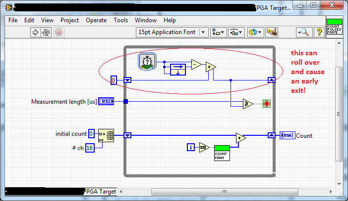
I wrote a little VI that counts ticks on a set of lines of DI for a period of time. It uses the number of cycles of VI to determine how much time has passed since he started running. The output of this VI is a U32, and subtraction function looks like it going to saturate to '0' if the number of cycles longer rolls. How can I handle this situation to prevent the VI to leave earlier?
Integer arithmetic must manage calculation rolling correctly (for example if your value is a U8 and you do 3-250, you should get 9). I guess (although I never checked) it works even in the FPGA. You can do a simple check yourself with explicit code. It would be nothing less than a complete cycle of safe, so it depends how much time it takes. If it is ms, it would take about 50 days. In your case, it seems that you have configured the service to be in us, so it would be somewhere more than an hour. If that's not enough, then you can maintain the real value in a U64 and then take the number of us that passing in each iteration and that adds to the U64.
-
Rinse the target DMA to host FIFO FPGA
I have a program that runs on FPGA waiting for a ppr pulse 1 a coder, then begins to acquire data based on 4096 pulses of ppr. After that it becomes 4096 pulses, it synchronizes the back upward with the pulse of 1 ppr and recidivism. If the encoder stops spinning in the middle of a revolution, I have a timeout will happen, shouldn't get a pulse of 4096 in some time. This way my code isn't stuck wait pulses if the encoder stops turning. Then, it warns the user and synchronizes backup with the pulse of 1 ppr when spinning resumes.
Well, the encoder stops at Midway through a revolution of spinning, I get a timeout, but now there are 2048 (4096 ppr * 0.5 revolutions) stale data points in the FIFO. I want to get rid of these points so that once it syncs back upward with the pulse of 1 ppr, I have data in the FIFO, all of the current revolution. I guess I could take the timeout error and trigger a loop on the side of RT that removes the elements until the FIFO is empty, but if it is not in time, before the encoder starts to turn once again, I still stuck with stale data. Maybe I need some sort of handshake with controls? I could also put FIFO for target on the FPGA for storing data and not the tail it to go to the host until it is all there. If I get a timeout, I could please rinse on the FPGA FIFO, because there is a method for flushing to target FIFOs.
No matter which deals with this problem before, and how to solve?
Hello
I think that your first method is the best option. When you save a timeout, have triggered a case on your side of RT first making a FIFO reading which returns the number of items in the FIFO (but reads the items suck) and then immediately do a read FIFO that reads the number of items remaining. This will clear your FIFO and it should run quickly.
Maybe you are looking for
-
I have found this problem with 2 different browsers, but had success with a 3d. I noticed that the file on Firefox was with Zoom Downloader download. Could be the problem? (Don't know whence came the Downloader Zoom). I use Firefox 18 and Win 7.
-
I love the new Walkman, the A17 is incredible, in any case, I beg you for the next generations of the Walkman you can take the following options: New song Pop Up http://postimg.org/image/rg3t223pt/ and Add in the trash http://postimg.org/image/5eapqa
-
When connecting line power screen bright decreeses, when I disconnect light increases. (Bright increases with the power of the battery). How can I adapt this function?. Thank you very much.
-
Licenses, IPS on pair of Cisco ASA 5510 active / standby
I have two ASA 5510 devices in Active mode / standby. I think of buying both used IPS modules and their installation. My question is, me 1 or 2 licenses IPS that requires? We are on 8.4 right now, and I see 8.3 Cisco changed license to c/o to wher
-
I am trying to export files Apple Pro Res 422 via Speedgrade and a video 1920x1080is entry of 10 minutes out to 89 GB. I used to export via Premier Pro and Media Encoder and Speedgrade interface seems sparse. I am fairly new to this and I feel that I