Filter to the measures function
Hi allIs it possible to use the filter to the measures also feature because we compare dates as well as measures such as below
FILTER ("1. Fact - order "." AMT of the command"USING (("Facture (avec fait 3) "". "")) (Promise date (with fact 1 & 3)"< @{date1} {date ' 2013-04-08'}) AND ((" Order Lines". ("" Date of shipment (with fact 1) "> @{date1} {date ' 2013-04-08'}) OR (command lines" ".) ((("" (With fact 1) shipping date "= date ' 1901-01-01')))
Here we must compare like measure1 < date2 then order AMT.
You can use the CASE WHEN, as angelique has said, the syntax would be like this,
-Case when
Mark done if this can help :)
Tags: Business Intelligence
Similar Questions
-
How to convert data from XY graph for type ' signal in "for measurement functions
Hi all, I have a driver file that generates the screenshot XY graph. I want to measure the period, using the measurement functions in the LabVIEW palette. Can someone tell me how to convert this type of signal "in". The X (time) and Y (power) are all there, but it causes an error when I son together?
Please see my attached code.
Thank you
Its ok people, I found a solution. See attached FYI.
-
Rank function without filter in the report
Hello
I have a problem with the Rank() function. The problem is the following.
I have a table with this train:
The user | DATE | Cost
User1. 02/12/2011 | 10.4
User1. 13/02/2011 | 11.1
User1. 13/02/2011 | 10.1
User1. 13/02/2011 | 8.1
User2. 02/12/2011 | 1, 4
User2. 13/02/2011 | 12.1
User2. 13/02/2011 | 22.1
User2. 13/02/2011 | 8.1
The RPD, I have a line of agregate under SUM (COST) and I need extract ranking you of this SUM (COST) by the user, user1 is 39.7 and the sum of user 2 is 43.7. If I show in the report of all users, the ranking is good rank = 1, rank = 2 by user1 and user2 but the problem is that I only want to show the User1, when I add a filter to the report user = 'user1', the rank value varies from 2 to 1. I need that the ranking value doesn´t change when I introduce a filter.
Any idea on how to solve this problem?
Thank youHi Antonio,.
On the rank in the answers column, modify the formula as shown below.
Case where username = "user2" so Rank (sum (cost)) 0 otherwise end
Then apply a filter on the column rank by rank > 0.
I hope this helps you.
Concerning
AP -
LAG function to get the value of the measurement for parent
Hello
I'm interested if there is no function in OLAP DML, which is similar to the function of TROLLING. LAG function returns the measured value for the previous dimension member (or a few members of the back dimension). I would like to know if this function exists which does not return a meaningless measurement for the dimension member value, but the measured value for the parent of the live dimension member.
Thanks in advance
Peter_parentrel relationship identifies the parent of each Member of the dimension of a hierarchy. use:
the time - dimension
time_parentrel - Member parent expression
time_parentrel (time_hierlist 'CALENDAR') - expression for parent along the CALENDAR hierarchySales - measure
Sales (Time time_parentrel) - expression returning sales for the parent of the current Member along the existing hierarchy.
sales (time time_parentrel (time_hierlist 'EXERCISE'))-expression returning the sales for the parent of the current Member along the FISCAL hierarchy.You can search the user's Guide the OLAP DML for many examples of the use of the OLAP DML commands/functions/objects in expressions.
All of these objects are automatically created/maintained while retaining the dimension from the front end (MN).For example:
(11g) OLAP DML users guide notions-> about-> OLAP DML objects given OLAP DML-> objects that support the use of hierarchical Dimensions section. -
How can I remove the search function of Joobers of Firefox?
I would like to remove the search function of my 8.0.1 Mac Joobers version of Firefox. This feature appeared all recently. I tried to remove the Joobers cookies and restart Firefox. Any other ideas?
Start Firefox in Firefox to solve the issues in Safe Mode to check if one of the extensions or if hardware acceleration is the cause of the problem (switch to the DEFAULT theme: Firefox (Tools) > Add-ons > appearance/themes).
- Makes no changes on the start safe mode window.
- https://support.Mozilla.com/kb/safe+mode
- Open the topic: config page through the address bar and do a search for joobers via the filter at the top of the about: config page.
- Reset all the joobers related prefs which appear "BOLD" (user set) via the context menu to their default values.
See also:
-
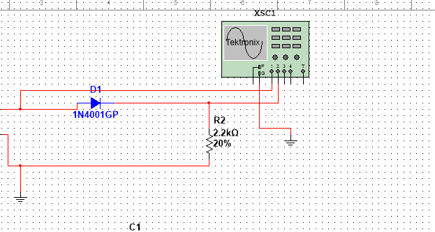
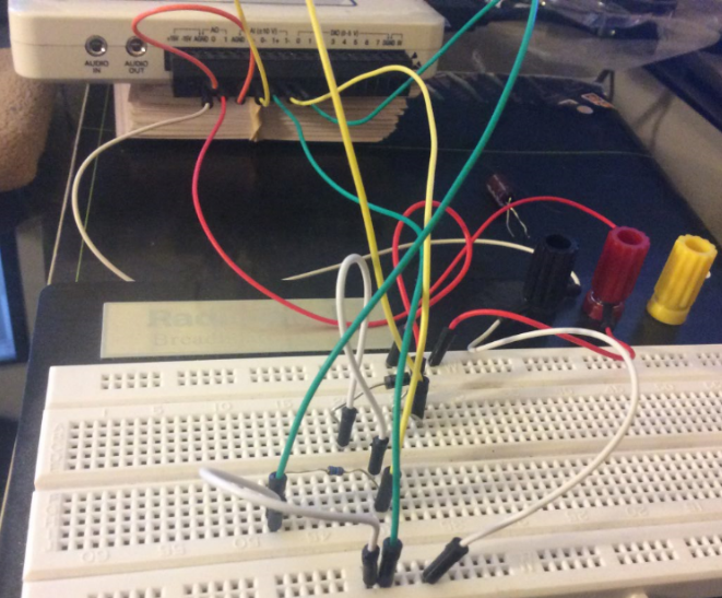
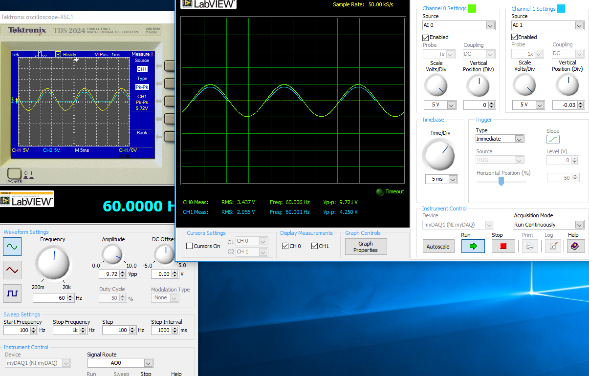
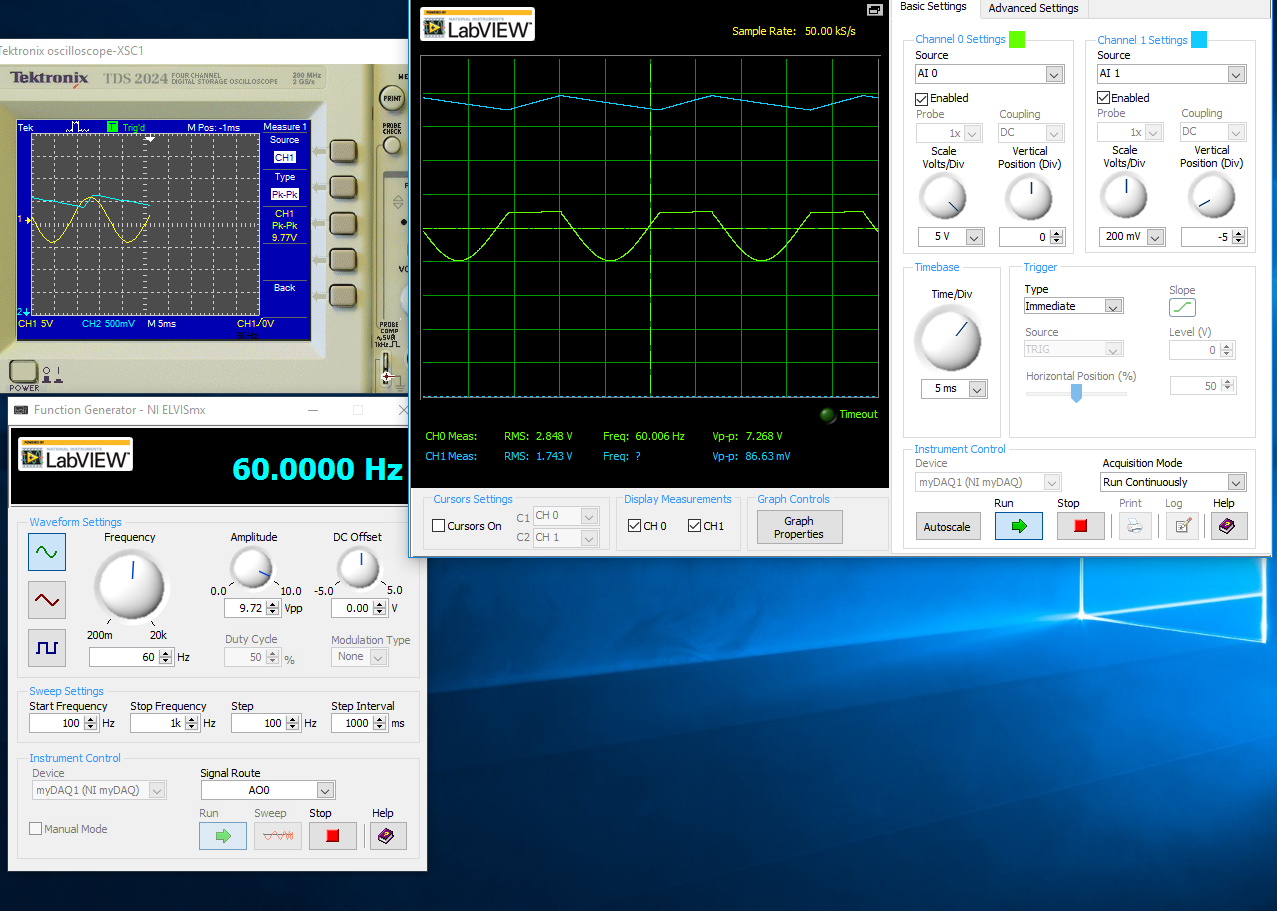
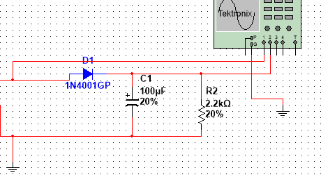
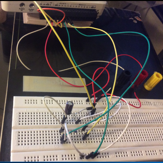
half-wave rectified filter circuit/oscilloscope measurement
Hello everyone, I hope I can get help on this fundamental issue, I'll have. University online, with which I will not help me, so I hope that I can quickly get assistance here.
I have the myDAQ NOR, I have to build half rectified filter circuit with a resistance 2.2kOhm, I also use the multi-sim to confirm the measures of waveform. Everything goes well on Labview multisims Tektronix Oscilloscope compared to before I connect a capacitor 100uF my comparison heres:
The model is just the Diode with a series resistance 2.2kOhm, I'm not sure if the analog inputs to the LabView Oscilloscope are configured correctly this is the air I get:
This satifies my simple comparison on the Multisim circuit, since I came here for a few hours to play with probes analog input, I know that something is wrong out of these measures, I get.
With a capacitor 100uF in parallel:
I think the question is how I inputs analog and STILL plugged, I'm not sure that this is where I would really like some help or any type of assistance. Once I get this set up right, I'll be able to take measures for the frequency, load DC, P - P Ripple voltage ripple and then move to a full-wave rectified circuit. I just started a course and received the myDAQ.
Henrik_Volkers wrote:
Compare it with the current specification of output of your myDAQ

Here is a link to the specification: http://www.ni.com/pdf/manuals/373061f.pdf
Henrik hit it on the head. The myDAQ can, at most, out 2mA with analog output. So, with a 2.2kOhm charge, which puts you in 4.4V without the diode. The led will also require an amount of current. According to my estimates, subject of 1mA (your pic is ~2.5V, divide by the 2.2kOhm to get ~ 1mA). You will see only that on the positive side of the sine wave as the diode blocks all the negative side.
The lesson here is to make sure that your outputs have enough power to do what you want. You can go to get a simple op-amp from digikey and use a follower of tension for editing the current upward. You will probably need another power supply or two (+ 12V and - 12V) to power op-amp.
-
Low-pass filter before the NI 5112
Hello
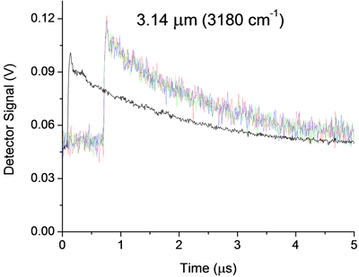
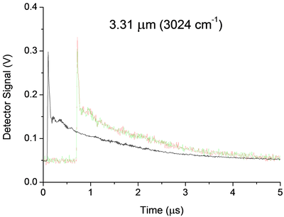
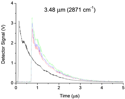
I currently use a 5112 AND measure the signal of an infrared detector in an experience of ring to the bottom of the cavity. Below are three examples of signals. My main question is how I can implement a low pass filter, passive preference, before my 5112 OR undistorted extremely my signal due to the impedance mismatch. Now a few details:
Some unique captures for each wavelength are shown in color, while average 25 pulses appears offset in black. The range and offset are chosen in each case in order to minimize the noise of "scanning". In the case of 3.14um, the noise that you see is about 25 times noise from scanning. They were taken without the limitation of BW and 100 ms/s mode.
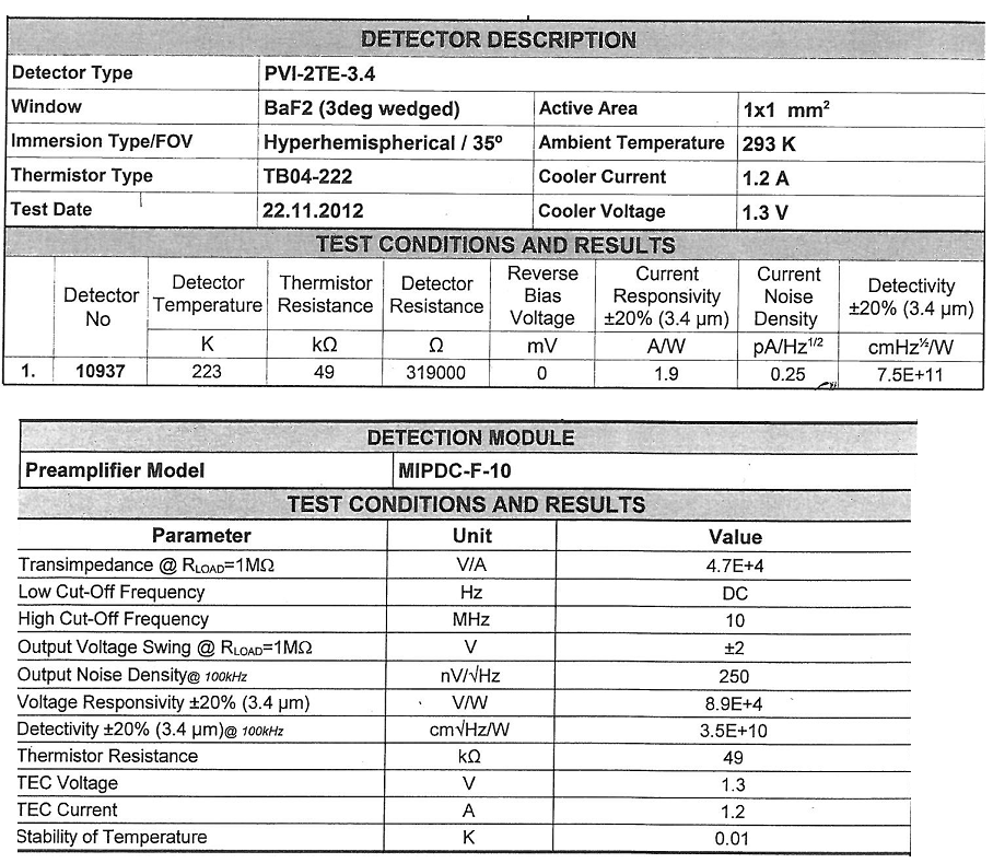
The detector (Vigo MIPDC-F-10) has a bandwidth of 10 MHz. I think it is a low impedance and is intended to be harnessed with 50Ohms, however its documentation confuses me, and I'm waiting for a definitive answer from the provider. 2.4 part of the manual says 50Ohms recommended, however the Datasheet and our map calibration (below) seem to suggest 1 MOhm is recommended!
There are a few strange oscillations with a period of almost 180ns in our signal that I thought were due to the impedance mismatch existed in the system before I changed it:
-Detector
-1 metre 50 Ohm SMC Cable BNC (RG-174)
-Inline BNC connector
-meter 5, 75 Ohm BNC to BNC cable
-Digitizer, DC, no BW limit, 100 ms/s, 1MOhm | 30pF
When I saw this configuration, I knew something wasn't right and I even he modeled in LTSpice and he showed the same period of oscillations. But now, the Setup is:
-Detector
-1 metre 50 Ohm SMC Cable BNC (RG-174)
-BW digitizer, DC, limit, 100 ms/s, 50 Ohm
And we still have oscillations, even if the period seems to have changed to 320ns all about. These oscillations, which remain are 99%, probably due to our drop-down ring cavity experiment, however if anyone has recommendations on possible causes or ways I can confirm it is not because of my chain of detection they would be more than welcome!
Now, the main question. Between the 50 Ohm 1 meter cable and the scanner I would insert a low pass filter. The BW limit has helped reduce the noise, but it can certainly still be further reduced without any lose to our signal. That's because we cut the beginning of the signal and then measure just the the decay time, which is relatively long and smooth (1 to 2 times 1/e US). Thus, in the future I may even want to try to eliminate the oscillations 320ns, but I'm afraid that this much filtering will distort the signal too. Therefore, for the immediate future I'm just looking to 'replace' the filter BW 20 MHz, with something like 1 or 5 MHz.
Of course, I would disable the BW limit on the digitizer to avoid additional confusion, but nevertheless, I'm not sure how to approach the problem. Usually I do a lot of research and try different solutions. However, I don't have access to all components to this work, so everything should be ordered, and I don't have a lot of time to experiment. Ferrites seem like a possible solution, however not sure how effective they are at this low frequency or the way they work with coaxial cables. I know that the filter passes low RC base, but the 50Ohms (or 1MOhm | 30 pF if I change it) seem to make it impossible. I guess an op-amp based one might work, however the large input impedance is the impedance of coaxial cable... etc...
All of the recommendations of the technique or red resources wort would be welcome. Thanks for your time.
A possible way to separate your artifacts electric and the cavity is relatively simple. You take the data at three wavelengths. For each of them, make a simple exponential decay (for example exponential Fit.vi) adjustment to your data, then subtract this signal. You should have something that oscillates on an average. Compare the residual signals for all three wavelengths, either visually or with something like a power spectrum. Anything in the three is probably the electronic (and you could possibly model and subtract it rather than trying to eliminate it). This could break if the rise time of the signals are different, because that will include elements of different frequency.
I am not convinced that you need to filter your signal before taking data. As you said, any filter will distort your final signal. My preference would be to take the raw signal and apply a filtering in the analysis. LabVIEW has a rich filter, so you can experiment later. If you apply a filter before the digitization of data, you take you will never receive data. However, if you know that your data has no component of your proposed cut filter frequency, you should be good. An analysis of the power on your current spectrum should tell you this. Be careful. Your form of rise time may have information you want later. If you filter, you will probably slow it down.
Good luck! Let us know if you need more information.
-
How to connect the parallel test using the logarithmic function Teststand database result
Hello
How can I connect a test result of 4 EHR tested in parallel using the logarithmic function Teststand database
I use Labview 2013, 2013 Teststand and sequential model.
The test is performed using a single digital card (SMU-6556). The FSD 4 is connected to the port of the digital map and is tested in parallel.
Currently at the end of the test, I would have a report with all the measures, but I need 4 reports (1 report / dut)
TKS
-
I have a question about the order of execution. In the WHILE loop, I have two things to measure, period and tension using the DAQmx READ functions for voltage and the meter. In the end, I want to collect these data as points almost simultaneously as possible, as a pair and then send them together to another piece of code (not shown here) which them will result in some sort of command for an engine. It would be run, and then I want to perceive the tension and the period at a time later and do the same thing.
(1.) I'm a little confused on what the meter of the READ function is back because it's a table. What is a picture of? I thought that it was up to the value of the individual periods between rising edges. The output of the counter 1 DBL d's a table. How many elements in this table, and what determines the size of this table? Are the elements of the array the individual delays between the edges? How many values are stored in the array by executing? We take the AVERAGE of the last 15 items, but do not know if we are throwing some of the data or what. How to understand the composition of this painting? How can I change the composition of this painting? Is it possible to measure only one period at a time, for example the time between TWO edges?
2.) Will this WHILE loop execute as it gathers tension and a "period table ' (remains to be understood by me) by TIME running in a loop? In particular, we want that the value of the tension associated with the value of the AVERAGE of the period "array", so we can use two data items to create orders of next control every time that the two values are reported. The structure for the delivery of vi will be attached data in pairs like this? I understand that one of the READING functions run not before the other function of READING in the WHILE loop. I want that the period "means" and "strain (Volt) collected at the same pace. This vi will he?
Thank you
Dave
Hi David,
I suggest including the DAQmx Start Task function. If it does not start before the loop, it starts the loop and work very well, but it is not as fast and efficient. In the model of task status, task wiill go to run the checked each iteration of the loop and then back the time checked running when it restarts.
The status of the task model: http://zone.ni.com/reference/en-XX/help/370466V-01/mxcncpts/taskstatemodel/
Kind regards
Jason D
Technical sales engineer
National Instruments
-
Sampling rate higher for the measurement of precision meter
I have a BNC 6259 M Series DAQ USB. I am currently using the DAQ Assistant to perform simple cash rising measured with the measuring mode single sample on request. I tested my VI with a known square wave with a function generator signal and it clearly lacks a few edges. I think that the solution lies in faster sampling. However, I was not able to understand how to use clocks to set up continuous sampling mode. I tried the forums and I found articles that were close, but not quite exactly the problem I am facing with as (http://forums.ni.com/t5/Digital-I-O/trying-to-use-NI-6251-s-DIO-port-as-input-and-output/m-p/448035#...) or (http://forums.ni.com/t5/Multifunction-DAQ/Using-Counter-of-PCI-6024E-with-Quadrature-Encoder/m-p/984...). Any guidance here would be great.
In fact, the calendar should not have anything to do with the edges being detected. Configuration of a sample clock for a county of just edge task allows you to enjoy deterministically in the account register and has no impact on the edges which can be counted. Also, the analog examples really have nothing to do with what you seem to be asking questions on.
... So it leaves the question unanswered as to why you might miss the edges. Perhaps the following information could shed some light on the question:
1. it is possible that you do not configure the counter exactly as you think you are. Can you post the VI you use? As a point of reference, count digital events shipping example does not use any clock sample timing and just questioned the value of the register count with a software loop, but the meter should not miss all this edge on the input source. There are examples that are timed by the material available as well, but this is not necessary, unless you need a constant specified dt between your counter samples. To use the examples of the timed sample, you will need to generate a clock of either another subsystem on the map or use an external clock.
2. assuming that the configuration of the counter is not the issue, there may be a problem with the method that you use to determine if you are away from the edges. How do you know that you are away from the edges? The function generator produces only a finite pulse amount? You start the meter before start out impulses?
3. If the two points above do not raise red flags, it seems likely that the meter is registered just not some of the impulses of your FGEN. Can I assume that the output of the FGEN is 0 - 5V TTL? What is its frequency and duty cycle? The maximum external source for the meter on the M-series products: DAQ (like the 6259) is specced at 20 MHz, but this depends on a clean signal with good connections. At frequencies above it, the bandwidth of the front-end of the PFI lines becomes limiting. If you have an available specification document for your FGEN I'd like to be able to see it.
I hope this gets you throw on the right track to solve the problem - impatience comes back with more information.
Best regards
-
How to insulate the wait at some of the code function
I'm building a system to applaud ecg with an external Stimulator using TTL of programming impulses to work along the side of the information obtained from the ECG. The most important of these features is the heart rate. However, whenever I activate my pulse trains in the code, the function DAQmx wait until Done.vi made a break measure everything in the code, including the part of my code that monitors heart rate, which uses time to for. What I would like, is the wait function only affects the pulse train generators without a break anything else in the code. Is this possible? And if so how can I get there?
I will attach my vi
Your problem is that everything is in the same loop. If the longest operation is going to determine the flow of the loop (and therefore rates of treatment). What you really need to do, is to separate tasks on separate loops. Use of queues or notifiers to communicate your data and commands between the loops.
-
Sinc filter using the DLL implementation
Dear all,
I'm trying to implement a sinc filter to a data flow that I receive from card FPGA. The C code is already working and now I'm trying to do is to implement the same algo on LabVIEW or make DLL and use it and I'm doing the later approach (don't know which one is better, any ideas?). I use this tutorial and it works very well for me in the case of the same example IE multiplication please see the VI attached.
I'm getting streams of raw data in the .csv file, and then I like to read this file. So what I have to do is apply a sinc filter so that every 32 points in this data set will be 1 sample for my position. I enclose you an example of a .csv file for data, a txt file of code C (for just to give you an idea of 3rd order) who work already, my dll and VI.
More specifically I have problems about the selection of parameters for the DLL for example what should I choose in the settings of the DLL LabVIEW function that corresponds to "unsigned char * data" as well as for others, as written in the C code. If someone can provide me with some VI he created to implement the sinc function or some ideas it would be also great.
Any help or advice you guys will be highly appreciated.Kind regards
Kuhn
There are a lot of discrepancies between what you do in your VI and that your text file watch is C code.
(1) the order of the parameters is VERY different.
(2) you are using int64 in the LabVIEW diagram, but int in C code. Under 32-bit Windows and 64-bit (and also Linux), an int type is ALWAYS a 32-bit value.
(3) read you in a table 1 d of channels and proceed to the node library call as native data. This requires a handful of LabVIEW LabVIEW handles string table. Expect a VERY big difference to byte array pointer in C code.
You convert the strings in a byte, and then configure the node library call to pass it as an array of integers not signed 8-bit, passed as a pointer of table data.
-
usefulness of reading the measurement file express vi
Hello
I found reading file express vi measure in LV7.1 does not read from the beginning of the file when you run it the second time. Instead, it resume from where it left off last time. Usually, the user would read the entire file measure each time. So when you try to read the second time, it will show an error window saying that it has reached the end of the file (because he was reading the entire file first).
I wonder how useful to resume from the last stopping point is? Is there a way to start over each time that the VI excute it?
I'm sure that's how reading file measure works 90%. Whenever she is called in a single run of the application, it will start off the coast where it was stopped. You will need to work with the low level screw to get what you want to do.
This Express VI works in a similar way the screws and the following functions:
Open/create/replace file
Read text file
Read binary file
Read the spreadsheet file
File dialog box
Scan to fileAnd, you can always use the node to set the file Position to set the position at the beginning of the file.
-
Using Sessions php component to the search functionality in a non-login site
Of course sessions are used for connection scenarios. My question is, since in a web page that has the feature of research and where the public user does not connect. but rather, is simply a search on a database table by using the appropriate html search entry form and accompanying the php script. a php session component is used? The user is connected to the database as part of the search function, so if a php session component is included in order to close this topic, assuming that the connection can be closed, using a session element, in this circumstance. Or well, the connection is closed all just when the user moves to another web page?
It seems for that database connection may remain open an excessive amount of time should the user not down the search page or a page of results. Thanks in advance for any input.
It seems for that database connection may remain open an excessive amount of time should the user not down the search page
Not how it works. As soon as the script runs, the database connection is released. It doesn't matter if the user is still looking at the page.
so include a component php session in order to close this topic
Also no how it works
For research, I use POST. You can also use GET. Using SESSIONS would not normally make sense, since the variable SESSION must get populated by POST or GET data anyway.
Sessions serve not only for the opening of the session. They are nice for shopping cart States peacekeeping because the user can leave the 'store' and go to other parts of the Web site and shopping cart data disappear.
I uses sessions to keep track of the language that the user selects and other important variables. I also put the language in the url parameters, but store it in the SESSION table is a fallback measure.
php session component
Just to be clear, SESSIONS are not part of PHP, even though they are frequently used together. SESSION, POST and GET are all part of the server environment.
-
Impossible to activate her comment and measurement functions
I need to extend rights to Reader users to add attachments by activating him commenting and measurement functions. However, when I try to register under > Reader Extended PDF > enable commenting on and measure nothing happens. I tested two other Reader Extended options: nothing happens when you select Add text in Documents, but I am able to save by using additional features allow.
The form created in LiveCycle Designer ES2 and is a dynamic XML form.
I tried to re-creation (copy and paste features) in static PDF format, but when the PDF file is opened in Adobe Acrobat, an Out of Memory error occurs. The form must be used for Reader and Acrobat Standard/Pro users.
I have created many other forms with this feature enabled, so am at a loss as to why it doesn't work now. I did all the recommended stuff (I think): re-boot, delete the temporary files, reader, the module is enabled (off and on again and the two parameters do not affect this)...
Thanks for your responses - I had a colleague with Acrobat to apply the characteristics and everything works now. It must be something in my settings Adobe somewhere that this prevents work properly on my pc.
Maybe you are looking for
-
Every once in a while my Firefox icon and cursor start to Flash - why?
I have no further details
-
Safari does not work after update 9.3 on air iPad and iPhone6Plus
Safari will not hurt after update 9.3 on the two air 6Plus and iPhone iPad.
-
Is the correct model U41-70 of Lenovo, how to find its drivers?
Hello I just bougth a new computer laptop, his model is U41-70 and the serial number is xxxxx. But I couldn't find his driver on the Lenovo Web site so I wonder is this a fake? If this is not the case, where I can find its drivers. I have bougth at t
-
Hello I want to buy a HD for my T61 and seen this HD: http://www.Newegg.com/product/product.aspx?item=N82E16822136280 is someone can you please tell me if this HD is compatible with my T61? This is my first time trying to install a new HD on my lapto
-
RAM for HP pavilion dv6 3004-SO
Hello I am writing from Denmark. I want to upgrade my RAM 8 GB memory. Product number: XB526EA #UUW Serial number: [personal information deleted] Processor bicoeur AMD Athlon (TM) II N330 ATI graphics card (ATI Mobility Radeon HD 5470) XT with 512 MB