FPGA DDS phase 64-bit register
Hello!
I have some difficulty in updating the code below to use a registry of phase 64-bit instead of just 32-bit or link. I can change the value of control to 64-bit data types, as well as pass the fancy addition with wrap vi to 64-bit. I'm not sure, but how should I change change of logic-5.
Thanks in advance!
http://www.NI.com/example/31066/en/
When you split a U64 you get two U32. The Subvi expected U16 (you see the points of constraint due to incorrect data types).
I suggest shifting the U64 3 bits, then divided in two U32, divide the top once again to the two U16. Since you staggered 3-bit the first 3 bits are 0, resulting in a 13-bit address. The lower U16 is for interpolation.
Tags: NI Software
Similar Questions
-
How to read the entire signed in the Modbus IO Server 16-bit register
HI, I'm using Labview 2011. I like read 16 bit holding register to another PC using Modbus.But option is there only to read "registry of operating as 16-bit integers from 0 to 65 535".
"But how to interpret as signed integers, as some registry values can have negative values". If the reading as unsigned integers, values is false. Is there a way to convert unsigned to signed integers integers.
concerning
Ahmed Tafesh
Yes, you can do the conversion... just be careful to not change its value or to complete something you need in the conversion process.
Since the block diagram, range of functions-> programming-> Digital-> Conversion
Try the I16 or the FXP. The I16 is a direct conversion, so you can't really control how it gets converted. The FXP you can right click and select properties to make the conversions.
If all else fails, you can do the U16 to binary to FXP to I16. It may be the long way to get there, but it should work.
R ^ 2 (Ryan)
-
CPU register accessible in LabView FPGA FlexRIO
Hello people, I wonder if it is possible to get the following behaviors of Labview. I think that it is not.
Description of the system: application of CVI which communicates with SMU FlexRIO via controls and indicators.
Problem: The design of a CPU-FPGA interface specification which lists the "books" as a combination of reading and reading/writing-the bit fields.
Example:
According to the specification, there should be a 32-bit register. 31: 16 bits are read-only, and 15:0 bits are read/write, from the perspective of the CPU. In the world of labview, I would just do a uint16 control and indicator of uint16 and do with it.
However, to meet the specification (written for microprocessor buses) traditional, a reading of 32 bits of an address should read back the full content of the 32-bitregister to this place (implemented as flops on the FPGA, with appropriate memory within the FPGA device mapping). In the same way a 32 bits of an address entry must store the values in this registry (properly masking wrote at 31: 16 bits within the FPGA device).
Is it possible for me to have a unique address (basically, a component unique labview block diagram) that will allow me to accomplish this behavior? It seems to me that the only solution is to pack my records with bit fields that are all read, or all the read-write in order to register in the paradigm of labview. This means that the spec should go back and be re-written and approved again.
Thanks in advance,
-J
Thanks for the detailed explanation. I am familiar with the reading and writing in the FPGA registers - I did a lot of work non-LabVIEW recently with an Altera FPGA. I haven't, however, used the CVI to LabVIEW FPGA interface, I only used the LabVIEW interface. I'm not sure if your question is about the CVI, LabVIEW FPGA interface or both.
JJMontante wrote:
Thus, a restatement of my original question: y at - it a mechanism with the use of indicators of controls where both the FPGA AND the CPU can write to the same series of flip-flops in the FPGA? If I use an indicator, the FPGA can write to the indicator, but the CPU cannot. If I use a control, the CPU can write in the control, but can't the FPGA. Is this correct?
On LabVIEW FPGA, a control and indicator are essentially identical. You can write a check, or read a battery / battery, using a local variable in the FPGA code. It is common to use a single piece of front panel to transfer the data in either sense, and it's okay if it's a command or an indicator. For example, a common strategy uses a Boolean façade element for handshake. The CPU writes a value to a numeric control, and then sets the value Boolean true to indicate that the new data is available. FPGA reads this numerical value, and then sets the Boolean false, which indicates the processor that the value has been read. The LabVIEW FPGA interface (side CPU) covers also all elements of frontage on the same FPGA whether orders or the lights--they can be as well read and written.
That answer your question at all?
-
I am trying to acquire data from a ni9222 located in the chassis-9014 9114, cRIO.
But for some reason, the output data type is used as a 24-bit fixed point number?
However the 9222 is module of the ADC 4 channels 16-bit 500ks/S.
I want to run the data via a fifo (target scoped) to power a 2 channel FFT module (coregen), which accepts fixed point 16-bit numbers.
I seem to be anyway to change or correct the accuracy.
I increased the fifo to 24 bits to try to work around the problem, but then I can't seem to massage the 16-bit required format (that it should have been originally)
All this in the area of the chassis/FPGA
In another section of my main FPGA vi, I 16 bits of the data of NI9215 quite happily was sent down a DMA FIFO for the time real cRIO and connected to a USB key without any strange problems.
PS are the example any screws available for the use of the FIFO coregen and the 7.1 FFT coregen?
I use the labview 11
In my view, that the data is being multiplied by a scale factor to convert the entry to volts instead of charges. I think it's so when you mix different modules with different resolutions of data acquisition, the outputs are in volts and can be compared, etc.. I know that I changed the properties of some modules for the former counties old-fashioned, but I don't remember exactly how I did it.
Bruce
-
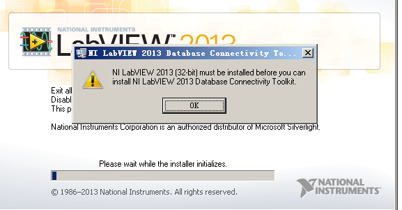
LabVIEW 2013 64 bit does not support the 'toolboxes connection database?
Hello
I have download the labview 2013 64 bit & registed with success
But encount a problem when I try to install "2013DCT"(database connectivity toolkits)
Don't LV2013 64 bit does not support this toolkit?
If Yes, where can I find the boxes to tools for 64-bit?
You can install the version 32 bits in a relavent LV and copy the installation.
/Y -
LabVIEW FPGA CLIP node compilation error
Hello NO,.
I work on an application for my Single-Board RIO (sbRIO-9601) and faced with a compile error when I try to compile my FPGA personality via the ELEMENT node. I have two .vhd files that I declare in my .xml file and all at this point works great. I add the IP-level component to my project and then drag it to the VI I created under my FPGA.
Within the FPGA personality, I essentially have to add some constants on the indicators and entries CLIP to my CLIP out and attempt to save/compile. With this simple configuration, I met a compilation error (ERROR: MapLib:820 - symbol LUT4... see report filling for details on which signals were cut). If I go back to my VI and delete indicators on the output (making the output pin of the CLIP connected to nothing), compiles fine.
I've included screenshots, VHDL and LV project files. What could be causing an indicator of the output of my VI to force compilation errors?
Otherwise that it is attached to the output ELEMENT, a successful compilation...
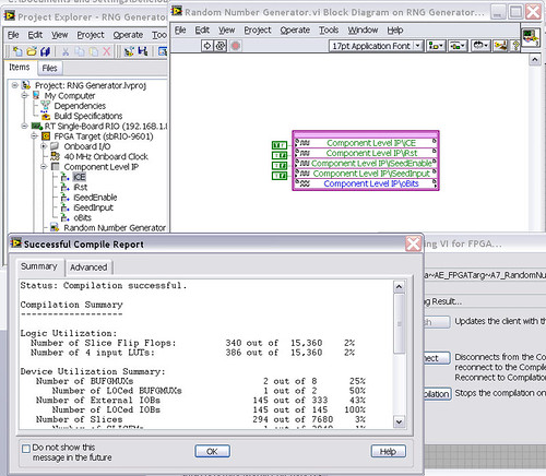
After that the output indicator comes with CLIP, compilation to fail...

NEITHER sbRIO-9601
LabVIEW 8.6.0
LabVIEW FPGA
Windows XP (32-bit, English)
No conflicting background process (not Google desktop, etc.).Usually a "trimming" error gives to think that there are a few missing IP. Often, a CLIP source file is missing or the path specified in the XML file is incorrect.
In your case I believe that there is an error in the XML declaration:
1.0
RandomNumberGenerator
urng_n11213_w36dp_t4_p89.vhd
fifo2.vhd
This indicates LV FPGA to expect a higher level entity called "RandomNumberGenerator" defined in one of two VHDL files. However, I couldn't see this entity in one of two files. If urng_n11213_w36dp_t4_p89 is the top-level entity, edit the XML to instead set the HDLName tag as follows:
urng_n11213_w36dp_t4_p89 Also - in your XML, you set the 'oBits' music VIDEO for output as a U32, however the VHDL port is defined as a vector of bits 89:
oBits: out std_logic_vector (89-1 downto 0)
These definitions must match and the maximum size of the vector CLIP IO is 32, so you have to break your oBits in three exits U32 output. I have added the ports and changed your logic of assignment as follows:
oBits1(31 downto 0)<= srcs(31="" downto="">
oBits2(31 downto 0)<= srcs(63="" downto="">
oBits3(31 downto 0)<= "0000000"="" &="" srcs(88="" downto="">Both of these changes resulted in a successful compilation.
Note: The only compiler errors when you add the flag because otherwise your CUTTING code is optimized design. If the IP is instantiated in a design, but nothing is connected to its output, it consumes all logic? Most of the time the FPGA compiler is smart enough to get it out.
-
I'm converting a piece of code from 8.5 to 2011. When I tried to compile the fpga vi to a bit file, I get the error attached. Why is this? Thank you!
The thing is that the only solution that I found about this error is to install a patch or repair/reinstall Xilinx or LabVIEW FPGA tools.
Christian
-
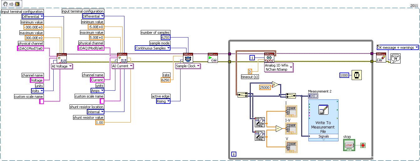
9225 and 9227 Module Constant phase shift (Drift)
Hello
I wrote a large VI and the am acquisition voltage and current with the 9225 and 9227. The phase of the voltage and current constantly derivatives. Its not just for phase a bit for all of the portion; the phase constantly cycles from 0 to 360 degrees. I have an excel file with locations showing what I mean. Series 1 = voltage 2 = current
I wrote a small VI to do the same thing with nothing extra. I have not yet add the data record. I just use a graph to plot the voltage and phase. The voltage and current were still off!
What do you think. Timers are bad on the modules? Slow computer? DAQ assistants are not good? IM using the internal timers in the modules.
Synronizing at the beginning does not help because the signals would still go out of phase when even later. The load is a piezoelectric tube.
I'm using Labview 2011 and NEITHER cDAQ-9178:
9225 3CH 300 Vrms 24 BIT simultaneous AIN
9227 4CH 24-BIT simultaneous AIN 5ArmsSee you soon
I forgot to change to continuous. I do usually. The major difficulty that I did was remove the trigger "Start Digital Edge" completely. The trigger wasn't working properly with what I put it in, "PFI0"... Once I took it out, I got a sample invaded. I played with the numbers of the sample for the clock sampling and playback. I don't know why to use 25000 everywhere has not worked. But when I dropped the numbers to 6250 or something of this magnitude, the VI finally worked.
The VI works with or without the clock I specified (Mod7/AI/sampleclock), which is great news! Thanks for this tip!
The current and voltage are finally in sync. They will never out of sync! Finally I can calculate the POWER!
This digital trigger was the worst headache... Thanks for the tips!
I write the VI and the code snippet to my completed solution.
-
2015 FPGA Module on windows 10
Hi all
I use module, labview and FPGA 2015 2015 (32-bit) on a computer laptop windows 64-bit 10. According to the white paper (http://www.ni.com/white-paper/52818/en/ ), the FPGA version of the module must be supported. However, I can't the FPGA VI to open and only get an error.
I'm trying to run a target FPGA simulation mode. The VI was created on a computer laptop windows 7.
Is there a possible way to open a FPGA VIs on windows 10?
Thanks in advance.
Solved! The mistakes have nothing to do with windows 10 or module FPGA. The VI I exported computer laptop windows 7 was actually corrupt and was recorded as then.
Although the VI is still running on windows 7, it seems that some memory settings have not been exported right and this caused the problem on the new laptop.
-
Error code 61499 after update license (FPGA)
Hello
I am a fairly experienced user of FPGA module. I have LabVIEW 2009 installed (version 9.0.0) including the FPGA on XP 32-bit module. Everything worked well and I had a project specific FPGA that had been built and run in the last month or so.
In the meantime, the license has expired, so I had to update the license. After update of the license, I made a trivial change in VI (default values has changed some entries to the front) and tried to compile and run.
This has generated the error-61499, with additional information:
Error starting compile step: make sure that a compatible version of Xilinx tools is installed in the location specified in the Setup from LabVIEW.
I looked after error-61499 in LabVIEW FPGA and a few other positions. I checked the path of compilation of LabVIEW FPGA registry keys and it seems fine (C:\NIFPGA2009\Xilinx\ISE). This directory exists and is the right size (3.74 GB). A temporary directory is created in C:\NIFPGA2009\srvrTmp\localhost. I searched the pearl58.dll file but couldn't find it.
When I look at the license installed recently and the license has expired in the License Manager NOR, I see no difference between the two other than the expiration date.
Summary: I had a working facility and the project, updated the license file and now get error-61499.
???
With the help of an Application engineer, I tried two things.
First of all, I tried to 'fix' the FPGA Module through the "Add or remove programs" utility in Control Panel. That had no effect.
Then, I downloaded and installed NOR-RIO 3.3.0 of the support zone, drivers and updates. That solved the problem!
So, for someone who has a similar problem in the future, try to reinstall the driver OR RIO.
-
conversion of an image of threshoulded on a scale of gray on 1473R (FPGA)
Hello
So I try to use an example called Image Processing with Vision Assistant on FPGA, edit and compress images PIV. However, when I try to use threshould function Vision Express sup - VI and then compile to my FPGA I get a black on the screen image, when I run the host VI. It could be due to the fact that the threshoulded image is black and red and the display configuration is U8 gray scale, but isn´t there is an option to display binary and I tried to use the lookup table to get a black and white image, but then he adds a new control, memory, I Don t know what to do with it.
If I could image as a binary file (and can view it), it would be perfect, but my programming really sucks and I Don t know how to do.
Thanks in advance!
To view the binary image on the host, use a binary palette: right-click on the image of the view control, click the menu on the palette, then select binary.
Another option is to convert the image on the Vision FPGA Wizard in 8-bit (Conversion function in the palette of shades of gray), and then choose the operators and multiply by 255.
The returned image will be an 8-bit image with values of 255 for pixels binarize.
Hope this helps,
Christophe
-
Firefox is in conflict with pxhlpa64.sys
(1) installed firefox 25 and auditor of race and got the 1st BSOD pxhlpa64.sys
(2) installed run fix automatix and fix all clicked again.
(3) restarted with the Auditor, got the 2nd pxhlpa64.sys BSOD
(4) automatic fix does not resolve pxhlpa64.sys.
(5) Firefox uninstalled, run the checker no. BSOD
100000% sure for my conclusion that firefox is in conflict with pxhlpa64.sys.
With firefox installed, two of my discs were read and write, but not safe for writing perfect.
Fix it please I run win7 64 bit, registered.
-
NOR CAN arbitration IDs failure
What is the breakdown of arbitration extended message ID?
Is this:
| x | x | 1. standard 11-bit | 18 - bit extended |
^ ^ ^ ^
Lsb msb lsb MSB
or
| x | x | 1. 18 - bit extended | standard 11-bit |
^ ^ ^ ^
Lsb msb lsb MSB
I could not find this information. I need the map CAN message structure in the implementation of Freescale, which presents itself as follows (32-bit):
| standard 11-bit | SRR | IDE | 18 - bit extended | RTR |
^ ^ ^ ^
Lsb msb lsb MSB
where SRR-online bit substitute remote request (request remote for the standard ID)
IDE => Extended ID bit. 1-scope id, 0-online standard id online
RTR => Request Remote for the scope ID.
Please advice.
The CAN bus does not send 18 0 bytes bytes padded for a standard identifier.
Most of the material has a 32-bit register for code.
For a 29-bit ID, you fill in 28:0. Identification of 11 bits, you fill 28.18 with the ID.
One of the higher bits 29, 30 or 31 indicates if the standard ID or extended by the concern of transmission.
-
Large number of samples by FIFO - avoid the saturation of the buffer target
My hardware is a PXI system, with a 7952R module FlexRio FPGA and a 14 bit 250 digitizer MECH NI5761. / s.
Most of the posts I've seen facing some Mech acquisition rates. / s or less and the number of samples of a few 1000. In addition, my analog read as well as write FIFO is in a SCTL don't while loop.
I want to buy say a 100000 samples each folder at the rate of 250 Mech. / s or more (millions of samples) at this rate.
Here's the basic problem I condensed (I think that is). I use the example of the Acquisition of SingleSample as a test project.
The FIFO DMA includes if the target and the host buffer. In practice, the maximum number of items that the target buffer can have is 32767.
Now, once on the host, I request more samples to 32767, the memory stream buffer target above (overflow), the host THAT FIFO read node waits forever, until finally the time-out has been reached and the number of items remaining in the FIFO (I guess the host buffer) get enormously large (scales with the time, the read node waits (plus I Specifies the time-out is the largest the number gets).
This is even if the depth of the FIFO is quite large (the host buffer is 5 x the number of samples per record).
First of all, this suggests that the DMO transfer rate is too slow. However, this also happens if I acquire only 125 MECH. / s (take 2 samples of ns, which means 14 bits 8 x 125 Ms, so about 250 MB/s. This is well below the rate of transfer, as far as I know, so it should not be the reason. Or am I oversee something?
The only solution I see is to limit the size of the records up. 32767 elements at a time.
Someone at - it experience with large quantities of samples on a FPGA - digitizer using a FIFO for reading configuration?
Just run the example CLIP unique sample vi and try to acquire 1000 samples, it will work. Try to acquire say 10000 samples and it will timeout as described above.
Thank you!
-
Map of CRC-16 TR - M Communication, Modbus RTU
I'm writing the procedure for generation of CRC - 16 for Communication if card - M from TECO Electric and Machining Company. Here's the algorithm that they provide to generate the word of CRC - 16 (attached is my attempt to implement, I look forward to suggestions). Here are verbatim:
A. load a 16-bit register with FFFFH. Call it the CRC register.
B. Exclusive or the first 8-bit byte of the message with the low byte of the CRC 16-bit registers, put the result in the register of the CRC.
Register to shift of c. CRC one bit to the right (towards the LSB), zero filling the MSB. Extract and examine the LSB.
D. If the LSB is 0, repeat the procedure C (another change). If LSB is 1, exclusive or the CRC register with the value of the polynomial A001H.
E. Repeat C, D, until the eight shifts were made. Wile to do this, a full byte will have been treated.
F. repeat the procedure B-E to the byte following the message so that all the bytes of the message is processed.
G. when the CHILD is placed in the message, TI upper and lower bytes are to be swapped.
If anyone understands this, please feel free to tell me where I would not (see attachment).
See you soon!
jmcbee,
I have attached a vi that comes with the Modbus LV library. You should get the answer.
Maybe you are looking for
-
How can I extend the warranty of my phone online?
Hello I would like to know how to extend the warranty on my phone online? My PC model: Compaq 620 Energy Star, product no.-XP866PA, country-India. Unable to get all the details on the site. My 1 year warranty expires the 10th of this month & I want t
-
Operation OutputDebugString() Win32 using LabVIEW
Is it possible to implement the ease of debugging using the OutputDebugString() API in Win32 in LabVIEW?
-
Windows XP crashed and turned off
I use Windows XP Professional Version 2000 service pack 3 on a Dell Optiplex 330 I have an xp update and a total clean spring who included the following: Check the disk*.tmp removalDisk CleanupDefragXP updatescan of MalwarebytesSpybot scanDefender sc
-
How to configure repeater using aironet 1140?
Hey,. I have an Air-AP1141N-A-K9 and I want to set up a Repeater bridge. I already have the web interface to the top. I was wondering how to set up as a Repeater for my main router. I think that it only supports 2.4 Ghz The IP address of my main rout
-
Hello The microphone of the SX20 has a serial number? Concerning Leonardo Santana