FREQ of FFT data
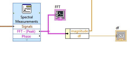
I am trying to extract the data of frequency of my FFT as I pull data from the scale, as a 1 d array, in order to write easily in an excel file.
As shown, I can get the delta-freq value, and I could do a loop for which calculates the values with the value of dF, but I would very much rather just extract the entire table that I do with "grandeur." Y at - it an option for this, or should I write the loop and calculate values?
Build yourself a table of frequencies, like this:
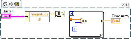
(Just realized the label of the indicator is time table - as I usually do this waveforms.)
You can also pass the array of magnitude in the loop with an autoindexing of entry, while omitting the size of array primitive wired for the number of iterations.
Edit - to answer your question, no, there's no other easy method I know.
Tags: NI Software
Similar Questions
-
Possible to add harmonic cursors to the fft data?
Hey Ron.
This could be an interesting XControl for you to take a look at:
http://zone.NI.com/DevZone/CDA/EPD/p/ID/6404
It is not automatically choose the peak values, but allows you to interactively move the sliders. It has also sideband cursors as well.
-Jack
-
DASYLab how to write data to a file every 15 minutes
Hi all
I use dasylab and datashuttle/3000 to record data. What I want to do is to write data to a file every 15 minutes. I use the milti-file, which can write data to the file diffenret, but how do I control the timing, as the journal data every 15 minutes automatically.
The other problem is that I use FFT analysis of the frequency spectrum. How can I determine the value of frequency where the peaks that happens.
Thank you
Write less data in the file that you have collected requires the reduction of certain data.
There are three techniques to consider.
With an average or an average of block - both reduce the data by using a function of averaging, defined in the module. To accomplish the reduction of data, choose block or RHM mode in the dialog box properties, and then enter the number of samples/data values that you want to reach on average.
Average - when you reduce the data, you also should reblock data using the block length of the change in the output parameter. For example if you enjoy at 100 samples/second with a block size of 64, the average module configured on average, more than 10 samples will take 10 times longer to fill a block. The initial block represent 0.64 seconds, the output block represent 6.4 seconds at a sampling rate of 10 samples/second. If you change the size of output in one block, the program remains sensitive.
Average block - average values in a block against each subsequent block, where the average is based position. The first samples are averaged, all second samples are average... etc. The output is a block of data, where each position has been averaged over the previous blocks. This is how you will be an average data FFT or histogram, for example, because the x-axis has been transformed in Hz or bins.
Second technique - separate module. This allows to reduce the data and the effective sampling rate jumping blocks or samples. For example, to reduce the data in 1000 samples / second to 100 samples per second, configure the module to keep a sample, jumping 9, keep one, jumping 9, etc. If you configure to skip blocks, you will not reduce the sampling frequency, but will reduce the overall amount of data in a single block 9, for example. It is appropriate for the FFT data or histogram, for example, to have the context of the correct data.
Finally, you can use a relay and a synchronization module module to control. For example, to reduce a sample data every 15 seconds, configure a generator module of TTL pulses for a cycle of 15 seconds of time. Connect it to a Combi trigger module and configure it to trigger on rising and stop the outbreak directly, with a trigger value after 1. The trigger output connects to the X of the relay command input.
In addition to these techniques, you can change the third technique to allow a variable duration using a combination of other modules.
Many of these techniques are covered in the help-tutorial-Quickstart, as the data reduction is one of the most frequently asked questions.
In regards to the FFT... use the module of statistical values in order to obtain the Maximum and the Max Position. The Position of Max will be the value of the frequency associated with the Maximum value. The output of the statistics module is a single sample per block. Look at the different FFT sample installed in the worksheet calculation/examples folder.
-
Convert Matlab FFT FFT LabVIEW
Hello
Nice day! Can someone here help me convert this Matlab LabVIEW code.
fftdata = abs (fft (data, 32768))
size of the data is the matrix of 1151 X 41. fftdata after the execution will be matrix 32768 X 41. I tried using FFT vi but I only got 1151 X 41.
Can someone help me and explain why?
Thank you...
Have you tried? The length must be equal to n.
-
Weird problem with control of the ring and foot
So I have some sort of weird issue with a control of the ring and a chart. I'm with LabWindows/CVI on a Windows 7 computer. The part of the program I'm looking at is basically to navigate through data - there are several "transition" (rehearsals experience), and you can choose the one that you want to watch in the list.
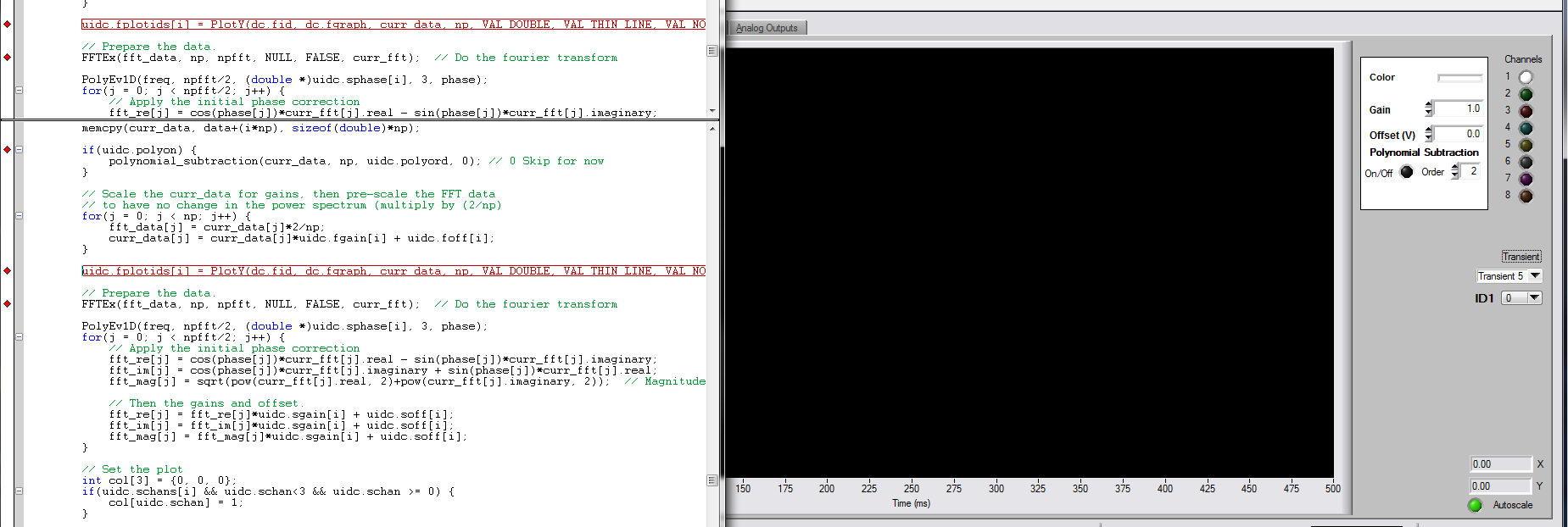
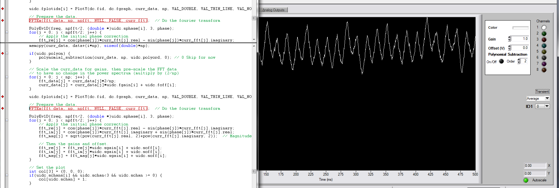
Normally, you would select transitional in the list, it plots the data, then it is done, basically. However, all of a sudden (don't know how long it spent for), when I select anything except 'Average', he made all the tracing and such, then it changes control of the ring to 'Average' (it is not plot the average data or generate all the reminders that I can tell).
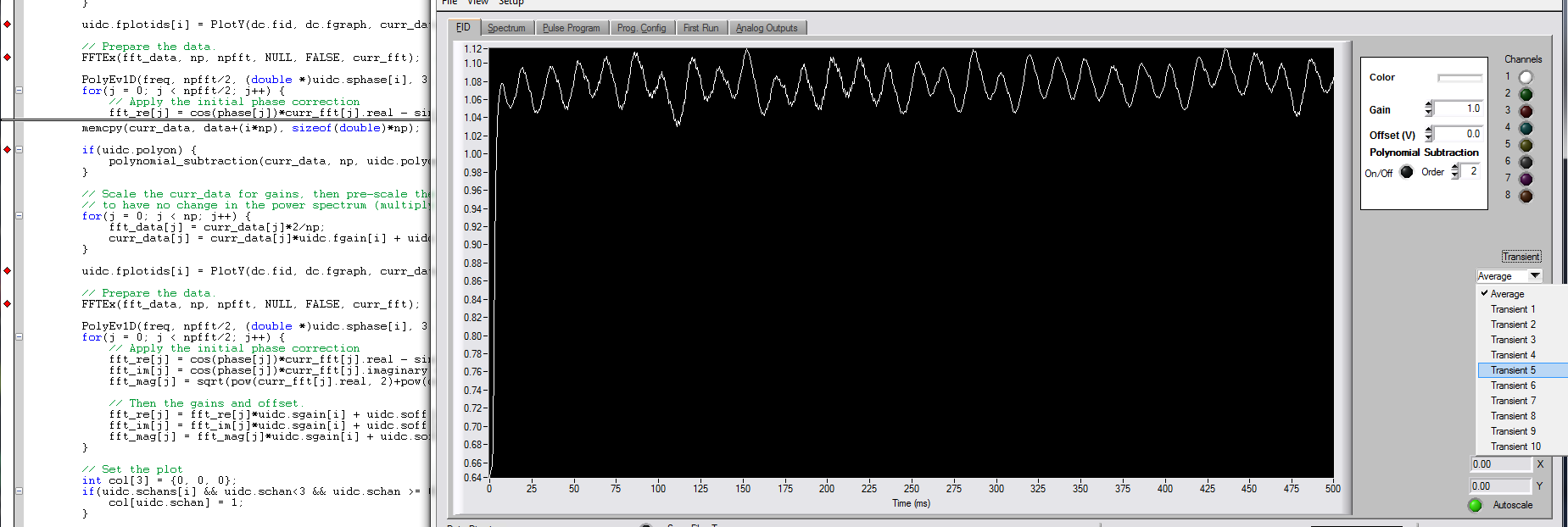
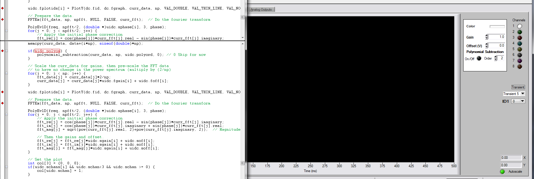
Now the thing the more bizarre as you can see below, it seems that the switch happens just when I draw something on the chart:
So, it's just weird. The code in this section is here:
   if(uidc.polyon) {
            polynomial_subtraction(curr_data, np, uidc.polyord, 0); // 0 Skip for now
        }

        // Scale the curr_data for gains, then pre-scale the FFT data
        // to have no change in the power spectrum (multiply by (2/np)
        for(j = 0; j < np; j++) {
            fft_data[j] = curr_data[j]*2/np;
            curr_data[j] = curr_data[j]*uidc.fgain[i] + uidc.foff[i];
        }

        uidc.fplotids[i] = PlotY(dc.fid, dc.fgraph, curr_data, np, VAL_DOUBLE, VAL_THIN_LINE, VAL_NO_POINT, VAL_SOLID, 1, uidc.fchans[i]?uidc.fcol[i]:VAL_TRANSPARENT);

        // Prepare the data.
        FFTEx(fft_data, np, npfft, NULL, FALSE, curr_fft);  // Do the fourier transform
DC is a structure that I use to better organize some UI controls and uidc is for display RAM variables, then dc.fid is the Panel that is embedded in the tab "FID", dc.fgraph = FID_Graph and corresponds to the chart control. Control of the ring is actually in a child Panel, dc.cloc [0]. FID_Graph has a point, it can produce, but the reminder is empty (no not coded something there yet).
I have also considered that perhaps something in another thread (I don't think there is, but whatever) I see is the cause, however, this behavior still happens on that line. I tried to break in different locations, on hold, then continues, as well by adding a loop containing Delay (0.01), a loop of 100 times. Always happens after the conspiracy.
Does anyone have any idea why this might be happening?
Hi Paul,.
I don't have a solution, but I wanted to point out that, even if you see the ring to change its value only when you call the function of tracing, that doesn't say what this function call that really changes the value of the ring. In CVI, some drawing operations are batched, for performance reasons, and the Panel updates only visually at certain times. One of those moments when you draw a chart data. Yes, the ring changes visually at this time there, but it is probably just 'catch up' a change earlier.
As you are looking through the code, when the value of the ring, you can use the term > command update UI to force the update panel, so that you don't have to wait for the tracing function and see if all goes well this change happening earlier.
Luis
-
Re: principal components analysis in LabVIEW
I want to the PCA of the FFT data (signal of known amplitude and time). I'm using labview 2009.I tried using the built-in pca.vi; but the difference in size of data. I am a student PCA for the 1st time in my life.please help.i do my last year on this project.
In fact, I have to feed the output of the FFT to a Network.And of neurons I do PCA to reduce the dimensionality of the signal so that it can be fed to the neural network.
Hello
The entrance to the principal components of the TSA (Array) VI analysis is a 2D table where each column of data represents the multivariate vector.
What is you are trying to achieve using the BCP vi?
If it's just the PCA and scores weight resulting. Then the first may want to identify the multidimensional data in you acoustic signal, thus forming a table of data and not 1 d 2D table, as shown in you post.
If a single element of the array 1 d of the sound signal contains various vectors, then you can acquire data over a period of time without any change in input parameters and then pass the array 2D resulting from data in the PCA.vi.
I hope this helps!
-
graph of a few blocks after a specific location
Hi I'm new to view lab and boasts a location on a chart to a number on the xaxis in the waveform graph. I want graphic 2 blocks of data after my desired location how can i go by doing this.
the location of the original is in time... but not in real time. and I need about 50 milliseconds of graphic data after my desired location, starting point.
OK, so I have a series of data with multile low point cusps in the waveform graph. I am able to chart he gave as a whole. now I want to focus strictly on the areas at dawn one at a time. and I want graphic 50 milliseconds of data after dawn. and then finally make a FFT data that results. and all of the cusp/w average FFFS together.
PS. I'm looking for in your vi prefious to see if it might work. thanx
-
Hello everyone.
I'm having some trouble for my project.
I would like to apply the Fast Fourier Transform on data acquired by an accelerometer. I do measures of vibration, data entry is a string it is then cut into the values of the axis 3 and converted into numbers.
What I would like to make is the FFT of these data, but I don't know how to "transform" waveform to apply the transformation.
Any help is appreciated.
My VI, commented, is attached.
Dear AndreasSchnaas,
Try the "worksheet to an array of strings.
To enable a detailed response, record the value by default in your orders and indicators data and post your VI once more. Data can be collected using your VI, unless the equipment is available for the user.
See you soon,.
-
I have already tasted the data of an input in the time domain signal. the signals are sampled by ADC and stored in excel file (about 16 K samples). I need to feed to the FFT VI for the plot of the FFT. I tried several bolts of FFT, but nobody does not accept data samples directly which is stored in the table 1 d. Any ideas? Thank you.
Hi ABM26,
Your input signal looks like a pure sine wave. You perform the FFT and get the amplitude. So you get two peaks in the result. I think it is the correct result. Why do you think the result of the FFT is false?
And I realize that you want to calculate what the power spectrum. You can use the Signal Processing > spectrum analysis > Power Spectrum.vi directly.
-
Cannot write the FFT of the integrated double data
I am a beginner to Labview environment.
I have acceleration Vs time dat file .lvm
Can I get the double integration of this
acceleration data for trip data.
Can I get FFT of displacement and displayed on the graph.
Up to this point VI works
But now if I connect this FFT of moving to 'write the measurement file' then it displays error.
Please help me... and correct the error... All I want is two column data, frequency andthe other of the amplitude of movement.
I have attached all files
I ask you to correct the VI please...
Thanking you!The concepts that you'll want to research are"matrices", "indexing of tables", 'automatic indexing', 'cluster' and 'type of waveform data'.
The loop IN the first VI I sent used the automatic indexation to take each element of a table 1 d of the clusters and perform operations on them separately to convert them to a waveform. Exit tunnel also uses automatic indexing so that the end result is a table 1 d of waveforms. I used the loop, so that no matter how many items appear in the table, you get a corresponding number of signals to the "writing on a file of measures."
In this case, because the output of the FRF is a single cluster (and not an array of clusters), the loop FOR was not necessary. The VI attached this time takes the output of cluster of FRF and maps the cluster to a single components build the wave function and you get a result of unique waveform.
I have no sound and Vibe loaded on my computer at the moment, so I can't run your VI and see the result of the integration of the snout to the Cloaca VI. The output data type is "Table 1 d of waveform" and your indicator and your two FRF can accept only waveforms. I put a function between integration and the indicator/FRF array index, but if there is more than one waveform in the table, it would be the wrong solution. My solution corrects the broken wires but throws waveforms 2,3,4... If they exist.
-
FFT vi truncate the FREQ of signal.
Hello
I noticed that the FFT vi truncate my signal. See attachments.
I'm basically the noise of a signal (I have both the phase - I - and out of phase - Q-signals...)
(Ignore the vi curve, it is just to remove the continuous component of the signal, it's irrelevant to this discussion).
Kind regards
Ali
You lose your calendar information for data going to the graph of the PSD. It works on arrays. The FFT functions assume a dT or dF 1. So when things are placed in the chart, you will see values up to 0.5 since Nyquist limits you to 1/2 of the sampling frequency. PSD2 graph doesn't have this problem because the blue wire of the DDT keeps the calendar data.
If you build your table in a type of waveform data and the boot in the value of dT, your data should look like the other graph.
-
Hi all... I learn LabVIEW since few days.i want to acquire a signal of pc6251 of acquisition of data and perform fft it can u people please help me? Thanks in advance
If you do only use LabVIEW for a few days, you should get familiar with it first by looking at some of the resources available here. After that, you can watch heredata acquisition.
After reviewing these documents, you can post back with any specific questions.
-
I would like to perform an FFT on a digital signal periodic sampling. For the moment, my signal is stored as an array of 16-bit integers (0-65534) item 8192.
I tried to connect this table directly at the entrance of the fft.vi X, but the data that comes out of the FFT {X} seem little logic (table length 8192 with spikes, the beginning and the end of it).
Any advice would be much appreciated.
Okay, that's better

The reason why you don't see the desired result of FFT is easy:
(a) you have a shift of 8000 to your signal. He is peaking at 0.
(b) your signal includes approximately 2.6 times. Given that the FFT concatenates virtually your signal from - inf to + inf in the time domain, your signal a 'jump' inside that create spikes in your field of frequency 'somewhere '. To prevent this, you can either use windowing or cut the signal of your time domain to contain a whole number of periods (which would then along 6400 samples).
hope this helps,
Norbert
-
Hello people,
THAT THE QUESTION PERTAINS TO:
I play on 2 parameters of a system based on the sampling time: Rotary position and vibration (accelerometer g increments). I want to take a fft based on the post to create a spectrum of the amplitude-phase speed order in / s. To do this, perform the following:
1 integrate (and scale) g vibration signal in the / s (SVT Integration.vi)
2 signal sampled vibration resample the same time at an angle similarly charged signal (ma-resample unevenly sampled input (linear interpolation) .vi)
THE QUESTION:
Order in which operations should be carried out, integrate then resample or vice versa? I didn't order would be important, but using the same set of data, the results are radically different.
OR ORDER ANALYSIS 2.0 TOOLSET:
I have the NO order Analysis Toolset 2.0, but I could not find a way to get the speed profile generation live to work with signals of position encoder DAQmx (via pxi-6602) quadrature. In addition, it seems that I have to specify all the commands I'm interested to watch, which I don't really know at this point (I want to see all available commands) so I decided to do my own fft based on the post to get a spectrum of the order.
Any help is greatly appreciated.
Chris
The order is to integrate the time domain of first - creating a speed channel. You now have a new channel of data. In general I would put this in the same table of waveform with waves of acceleration time.
Then re - sample your acceleration and/or your speed signals, and then you can calculate the spectrum of the order.
-
2 data columns of the worksheet in the indicator and a FFT
Description of the problem:
I have ben far from labview for many years. Now I am taking 2 data worksheet columns, read them in the 'read delimited spreadsheet vi', and view the two columns on the façade of my
VI. I can get only one column to display.so I want to draw the power spectrum of these data without having to use additional
loops, arrays, etc.LabVIEW is an example vi that is half of what I want to do
(Amplitude of the spectrum (sim) .vi). The spectrum analysis is performed using the entries from a signal generator vi instead of reading of a worksheet. Also the (Amplitude of the spectrum (sim) .vi uses a real world vi which produces an index of time for the x axis. It also adds noise to the data, to which I do not.
I see the problem.
Your delimiter for the file playback. You show a comma, but it is actually a comma and tab in there.
Right-click, then set it to \codes see of display style.
Delete the content of this constant and re-enter the comma.
Maybe you are looking for
-
Email + reminders / iCal (at worst)
Hello world How to create a task from an email? By dragging the letters to callbacks in the dock icon does nothing :-( I use El Capitan, 9.3 and reminders 3.0 Mail. Thanks in advance!
-
Home Page layout option does not work. Home page comes down to Modzilla Firefox Start Page.
Homepage layout option does not work after saving a new or different homepage on Firefox 19.0. When you open a new page (not tab) it always comes back to the default "Modzilla Firefox Start Page" value anything.
-
Hi, I have a laptop Toshiba Satellite A10 with Windows XP Pro and I upgraded the RAM to 256 MB 510. But... does not work all my new game on it! The laptop must be pretty hard! I've updated all the drivers... but still nothing! Can someone tell me wha
-
HP Envy 4500/Series: Cablelink (Austrian cable service) / installation HP Envy 4500 series problem
Hi, I have a new HP Envy 4500, and it does not connect to my wireless network. He sees the correct SSID (using WPA - PSK / TKIP or AES), but he will not join the network after providing the WPA key. Printing test results shows a FAILURE on > paramete
-
HP laptop, 2000 - 2b29WM: Motherboard upgrade compatibility
Hello I have a HP 2000-2b29WM (comes with Windows 8 and updated to 10) and am looking to upgrade my processor without changing the card mother (685783-501). I found a list of all the processors that are supported by the family of 2000, but I need to