Re: principal components analysis in LabVIEW
I want to the PCA of the FFT data (signal of known amplitude and time). I'm using labview 2009.I tried using the built-in pca.vi; but the difference in size of data. I am a student PCA for the 1st time in my life.please help.i do my last year on this project.
In fact, I have to feed the output of the FFT to a Network.And of neurons I do PCA to reduce the dimensionality of the signal so that it can be fed to the neural network.
Hello
The entrance to the principal components of the TSA (Array) VI analysis is a 2D table where each column of data represents the multivariate vector.
What is you are trying to achieve using the BCP vi?
If it's just the PCA and scores weight resulting. Then the first may want to identify the multidimensional data in you acoustic signal, thus forming a table of data and not 1 d 2D table, as shown in you post.
If a single element of the array 1 d of the sound signal contains various vectors, then you can acquire data over a period of time without any change in input parameters and then pass the array 2D resulting from data in the PCA.vi.
I hope this helps!
Tags: NI Software
Similar Questions
-
Image analysis of LabVIEW or to work on an exe file
Hello
I have a labview program that uses the IMAQ Toolbox and works very well. But when I do an exe file and run it on a computer with Labview run time engine installed, I get errors that the Vision_Development_Module is not found and the sub live cannot be used.
Could someone tell me what could be the problem and how I can solve this problem.
Thank you
You also need the Vision runtime installed.
-
Subtract the average of a matrix of each element
Hello
I make a principal components analysis I have an original power of real matrix a matrix of covariance which gives the average to one of the nodes and want that subtract from each element of the matrix to form a new matrix. If it's hard to connect to the average of the covariance matrix is it possible just to find the average of the original matrix, and this by subtracting each element of the matrix to form a new matrix.
Thanks for your help
Concerning
Canalian
The average of a 2D array is simply the sum of all the elements, divided by the number of items (= the product of the dimensions).
All you need is the following (works for arrays with more than 2 dimensions):

-
Use of LabView for exploitation of Bosch Rexroth HCS01
Hello people,
I am a student assistant and my current project is to complete what was launched in a work of degree more than a year ago: to build an experimental platform to test the effect of superconductivity on maglev technology. Part of this experimental platform is a precision three-rail network operated by compact inverters HCS01 (IndraDrive Cs) by Bosch Rexroth.
My question is: is it possible to use LabView to operate the three axes of a central VI?
I have already connected all three compact inverters to a computer and I am able to operate using most Ds-startup-easy mode, but I can only operate separately and not of a single window.
Thanks in advance, any help would be appreciated!
Greetings,
Paul Masuch
Hello world
I just found this forum article on control components Rexroth with LabView and as a representative of Rexroth, I disagree that West no way is easier to control than using Ethernet/IP.

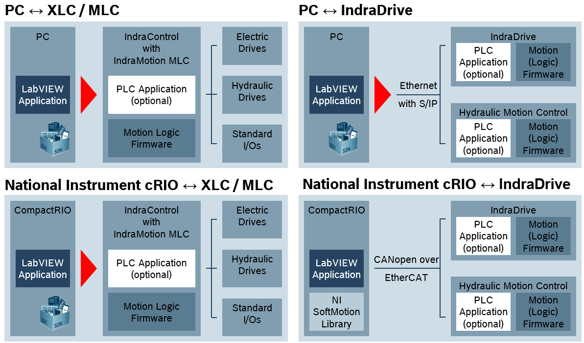
We have an official partnership with National Instruments, and offers a complete Package of VI for all our components (IndrDrives and IndraControl automata) to access all the features of a PLC or lead of Bosch Rexroth. This is possible thanks to our Open Core of Bosch Rexroth and our open approach we take with our automation components. For controllers the VI contains more than 850 screws to communicate directly from your LabView execution to the controller. These packages are completely free for you and you can download the packages from our Web site
http://www.boschrexroth.com/OCE
(access after registration in our network in engineering).
In addition it s also possible to control our readers a cRIO OR using the Council of Europe.
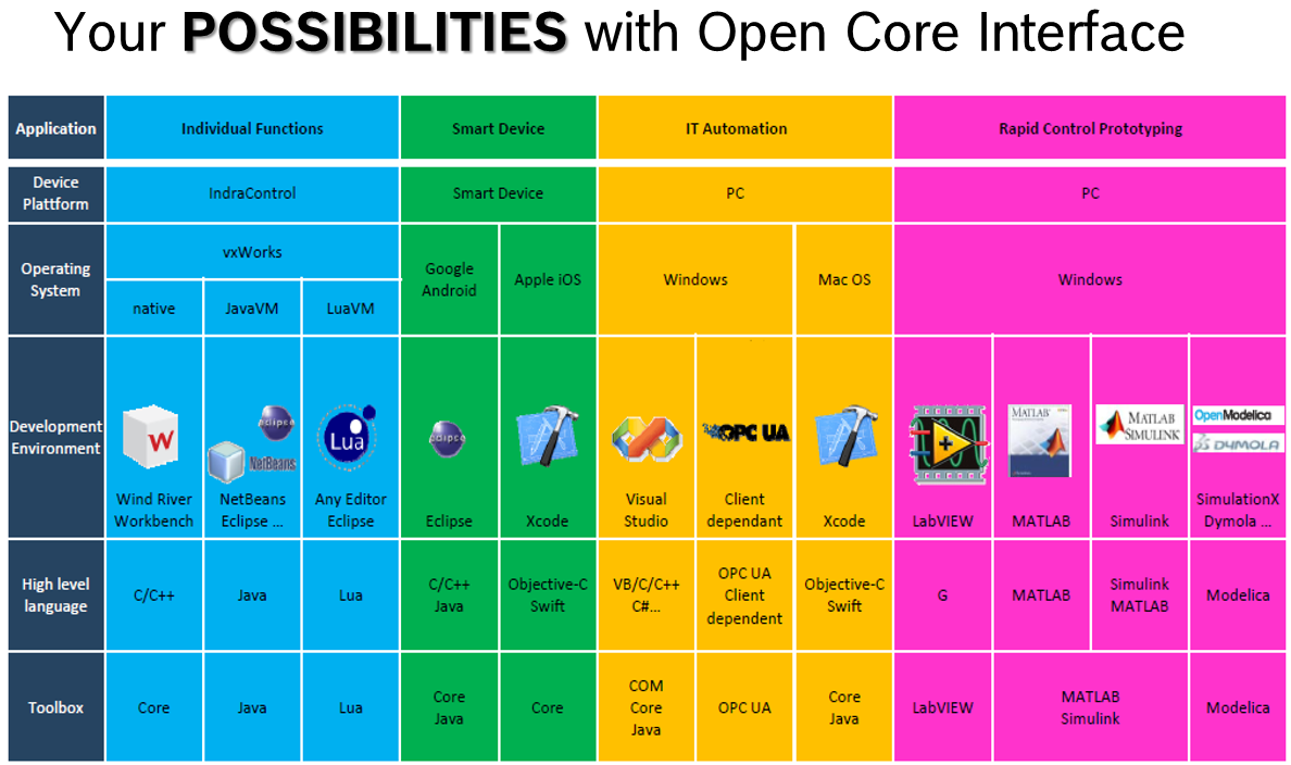
Here's a sneak peek of our open main Interface feature. There are SDKS for several languages of programming and several technologies including National Instruments Soft - and hardware.
So you see, West don't need to learn PLC programming, when you want to connect LabView to Automation from Rexroth.

If you have any trouble Don t hasitate to contact me!
Best regards
Tammo Schwindt
Application engineer
Bosch Rexroth AG
-
Is the old HPAL now analyse multi-hearts and Sparse Matrix Toolkit
I am trying to find a download for the HPAL used be offered by laboratories OR. This is supposed to be an addon for LabView now NEITHER and I am looking for the download.
Appears it in two possible addons that HRT has become; either the Toolbox of advanced treatment, which costs around $1500 or multi-hearts and Toolkit of sparse matrix analysis I think that it's free. No one knows what has become the HPAL?
Yes, you are right...
the High Performance analysis library was packed to be called analysis of LabVIEW Multicore and SPARC Matrix:
http://sine.NI.com/NIPs/CDs/view/p/lang/en/NID/210525
And it is always free to use.
I hope this helps.
-
Read a 2D array in ResultList with LabVIEW
At the end of my sequence, the of I analysis under labVIEW ResultList pour create an Excel file.
And in my results, I have a curve in an AdditionalResult don't wish retrieve the values.
These values are UN table of in 2D. When I professional size (GetNumElement) ca gives me the total number of "elements of the two dimensions of the array and not the depth of the table." In addition, I have an error if I do a GetPropertyObjet on this 2D chart to read each item.
How can I read the values in this table 2D?
Thank you
Patron
Hello
Here is a small example of use of ArrayDimensions
-
How to control NI 2503 PXI using labview?
Hello
I am vishal.
I have a job where I have to monitor the temperature of the various components.
LabVIEW platform is used to make a software that takes the output of thermistor through NI PXI 2503 multiplexer and converts it into digital
using or pxi5152 digitizer.now I have to control the two instruments of this and take values of the digitizer.
but the problem is that I don't know who you screw to control these instruments, because I do this first time.
I just know that the NIDAQmax screws can be used, but do not know how to use it.
Please give me a little early to make this program.
Thank you.
You can find this useful: combined with the switch Modules OR PXI high-speed digitizers measures. Basically, OR-Switch is used to control the multiplexer.
-
Value of updating after each sequence of dish
Hello
I'm doing a labview program analysis principal components. My program works well, but since it is tons of calculation it takes too long and there is no way of knowing if all the steps is going well. I'm putting some kind of progress is in my front panel that tell me what stage of the program. The vi for progress bar I found works well with the loop 'for', but I don't have a lot of loop and but I have my program have step 6 and I used the flat sequence for each step. Is there a way to update the value of slide after each sequence of dish. I'm using Labview 8.2 and I have attached a picture of a vi model which has a blade and has four sequences flat and each sequence a 1 second delay. I want the value of slide to day as the first dish to pass to other sequence data.
Thanks in advance
Yogesh
You can use a local Variable for this... right click on the slide-> Create-> the local Variable.
Use a local variable whenever you want to update the value.
-
Low-pass filter before the NI 5112
Hello
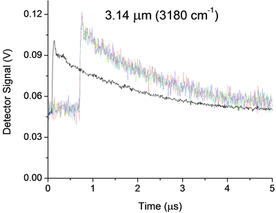
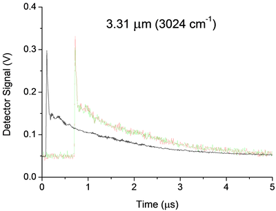
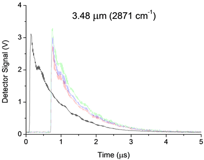
I currently use a 5112 AND measure the signal of an infrared detector in an experience of ring to the bottom of the cavity. Below are three examples of signals. My main question is how I can implement a low pass filter, passive preference, before my 5112 OR undistorted extremely my signal due to the impedance mismatch. Now a few details:
Some unique captures for each wavelength are shown in color, while average 25 pulses appears offset in black. The range and offset are chosen in each case in order to minimize the noise of "scanning". In the case of 3.14um, the noise that you see is about 25 times noise from scanning. They were taken without the limitation of BW and 100 ms/s mode.
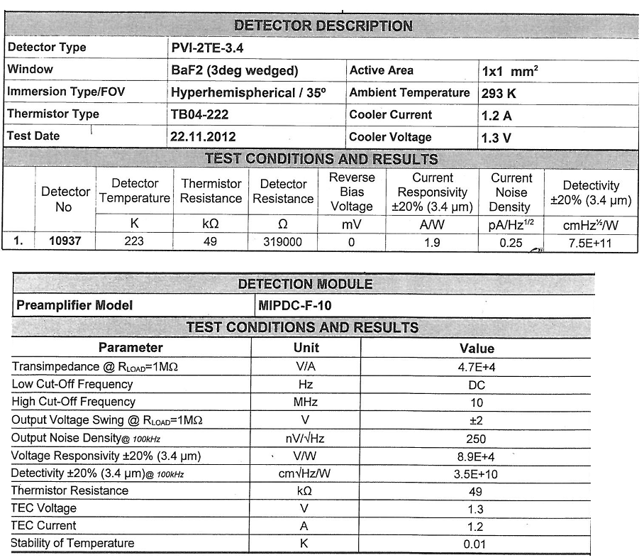
The detector (Vigo MIPDC-F-10) has a bandwidth of 10 MHz. I think it is a low impedance and is intended to be harnessed with 50Ohms, however its documentation confuses me, and I'm waiting for a definitive answer from the provider. 2.4 part of the manual says 50Ohms recommended, however the Datasheet and our map calibration (below) seem to suggest 1 MOhm is recommended!
There are a few strange oscillations with a period of almost 180ns in our signal that I thought were due to the impedance mismatch existed in the system before I changed it:
-Detector
-1 metre 50 Ohm SMC Cable BNC (RG-174)
-Inline BNC connector
-meter 5, 75 Ohm BNC to BNC cable
-Digitizer, DC, no BW limit, 100 ms/s, 1MOhm | 30pF
When I saw this configuration, I knew something wasn't right and I even he modeled in LTSpice and he showed the same period of oscillations. But now, the Setup is:
-Detector
-1 metre 50 Ohm SMC Cable BNC (RG-174)
-BW digitizer, DC, limit, 100 ms/s, 50 Ohm
And we still have oscillations, even if the period seems to have changed to 320ns all about. These oscillations, which remain are 99%, probably due to our drop-down ring cavity experiment, however if anyone has recommendations on possible causes or ways I can confirm it is not because of my chain of detection they would be more than welcome!
Now, the main question. Between the 50 Ohm 1 meter cable and the scanner I would insert a low pass filter. The BW limit has helped reduce the noise, but it can certainly still be further reduced without any lose to our signal. That's because we cut the beginning of the signal and then measure just the the decay time, which is relatively long and smooth (1 to 2 times 1/e US). Thus, in the future I may even want to try to eliminate the oscillations 320ns, but I'm afraid that this much filtering will distort the signal too. Therefore, for the immediate future I'm just looking to 'replace' the filter BW 20 MHz, with something like 1 or 5 MHz.
Of course, I would disable the BW limit on the digitizer to avoid additional confusion, but nevertheless, I'm not sure how to approach the problem. Usually I do a lot of research and try different solutions. However, I don't have access to all components to this work, so everything should be ordered, and I don't have a lot of time to experiment. Ferrites seem like a possible solution, however not sure how effective they are at this low frequency or the way they work with coaxial cables. I know that the filter passes low RC base, but the 50Ohms (or 1MOhm | 30 pF if I change it) seem to make it impossible. I guess an op-amp based one might work, however the large input impedance is the impedance of coaxial cable... etc...
All of the recommendations of the technique or red resources wort would be welcome. Thanks for your time.
A possible way to separate your artifacts electric and the cavity is relatively simple. You take the data at three wavelengths. For each of them, make a simple exponential decay (for example exponential Fit.vi) adjustment to your data, then subtract this signal. You should have something that oscillates on an average. Compare the residual signals for all three wavelengths, either visually or with something like a power spectrum. Anything in the three is probably the electronic (and you could possibly model and subtract it rather than trying to eliminate it). This could break if the rise time of the signals are different, because that will include elements of different frequency.
I am not convinced that you need to filter your signal before taking data. As you said, any filter will distort your final signal. My preference would be to take the raw signal and apply a filtering in the analysis. LabVIEW has a rich filter, so you can experiment later. If you apply a filter before the digitization of data, you take you will never receive data. However, if you know that your data has no component of your proposed cut filter frequency, you should be good. An analysis of the power on your current spectrum should tell you this. Be careful. Your form of rise time may have information you want later. If you filter, you will probably slow it down.
Good luck! Let us know if you need more information.
-
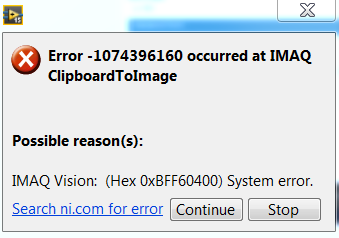
System error IMAQ using IMAQ Clipboard to Image
Hello
I have a VI that prints screen then use the Cliboard IMAQ to Image function to get the image into something that I can handle in LabVIEW.
It works perfectly when I'm in the LabVIEW environment. As soon as I select any other program LabVIEW throws the below error. I don't know if it is a mistake to LabVIEW or something to do with how the window Clipboard works.
Any help would be appreciated, or any other ideas of how to take a picture of what is on my computer for analysis in LabVIEW.
VI attached below - LV 2015
Hello
I can get the .VI for work in any active window if I change the I8 second from the node of function call library from 0 to 1.
I hope this helps.
Kind regards
Nathan
-
More 1997 PCI - CAN, how to put NIDeviceNet.llb screw LV6.1 to LV2012
Hello
I've got this old system on Windows 2000. There * a lot * of calls to the screw in the LabVIEW 6.1 DeviceNet.llb, called DNET screws...
If I've upgraded to LabVIEW 2012 and got a new NI PXI-8532, what it would be like to get the old code to work? Is there a new library / api for LabVIEW for devicenet? Or all the screws in the current library of devicenet LabVIEW have the same names and Connector components as in LabVIEW 6.1?
(I talked to a very good industrial AE to Com, but why can't I use my Premier Support to speak to one * DeviceNet * specialist at OR?)
CC
There is a white paper on the passage of the old code of Dnet1.x to IndCom for Devicenet 2.x code: http://www.ni.com/white-paper/14074/en
DirkW
-
MAX does not see the cRIO modules!
Hello
I have a cRIO-9073 and C 3 (9401, 9239, 9263) modules installed in slots 1-3 respectivly. I can configure the chassis correctly upon arrival 2 months ago and I managed to acquire by a module 9234. Now that the 3 mentioned c modules arrived I installed and have a problem - MAX of nothingness, or analysis of LabVIEW RT engine cannot see modules. Attached are MAX.png and DiscoveryStatus.png that depict. NOR-RIO is version 4.00 and corresponding set is completely downloaded to the cRIO. I do not understand the concept of software cRIO yet but I'm positive, that is the same as used to work the first time that I had tried. The network is OK - host is 100.0.0.1, cRIO is 100.0.0.100 and they see.
I susspected that perhaps specific drivers are needed for these particular C failet, but I can't verify that the status of software.
Basic details to accept and understand the CompactRIO concept is spread across many different documents, and it's really hard for the newbees to grasp, so debug/fix situations.
Does anyone have an idea what is causing my problem?
Thanks in advance,
-
HI @ all
I'm looking for info on the file system that works on my cRIO9014, the system includes the following components installed:
- LabVIEW time real 9.0.1
- Web server for LabVIEW RT 2.0.0
- Network Variable engine
- NOR-RIO 3.4.0
- NI-VISA 4.6.2
- NI-VISA 4.6.2 Server
- Run the engine for web services 2.0.1
- Editor of State system 1.1.0
- Customer support variables for labview rt 1.6.1
I would like to know what file is generated and where is it end when I deploy my RT - App?
Thanks for your help
Hello Thomas,.
Have you seen the RT system replication tools (http://zone.ni.com/devzone/cda/tut/p/id/3937)?
I have not used it myself, but based on the Dev box article, you should be able to make and store a number of different images that can then be deployed in your cRIO targets.
Sebastian
-
Help with fft vibrations without using the package of noise and vibrations
I'm looking for help in the analysis of vibrations. I use an example updated NI 9233 VI, to get a signal from the accelerometer for display using a FFT power spectrum. I'm not entirely sure if it works, because it's the first time I've ever done vibration analysis on LabView. So if you could explain a thing or two about vibrations or TFF, I'd be more than willing to hear from you. I have included my code along with a photo of an analysis of vibration of the computer, I work with. (even when I don't know if his work that I just thought it would be good to show an output)
Brandon
Data sheet:
I have LabView 2011
I FPGA, real-time
I have a model of research of Wilcoxon accelerometer 797-33
With an NI 9233
On a cRio-9012
Hi Brandon,.
You can use the FFT Complex (photo attached) to calculate the magnitude of the acceleration at different frequencies. You will need to take a little further to build a new waveform with this release, which includes d0, df and the output of the FFT. In order to calculate the df, please refer to the user manual on page 10-3. With respect to the scale that is output by the FFT, it must be same as input. Hope this helps to answer your questions. Thank you!
See you soon,.
CARISA Leal
-
Can I broadcast a VI wrapped as a DLL?
I'm working on a project that has some components written in LabVIEW and others in C++. The C++ code requires a function that would be more easily by encapsulating a single LabVIEW as a DLL function. Is this right from the point of view of licensing?
To clarify, if I have a valid license to create the dll with LabVIEW and will have them, that I can broadcast a dll that encapsulates a single function to LabVIEW? It is for use in a larger project and not an attempt to provide a package of functions of LV wrapped for use by a third party.
Since you have the right to create DLLs I don't see why not. Isn't the point of DLLs to encapsulate functions more or less complex?
/Y
Maybe you are looking for
-
Nodes property and rings of Menu
So I have this multimeter I need to make a driver for, and it has so many modes/scales of operation it will be a pain. So that's what I'm working with, there are a lot of 'functions of measure', including the tension continues, alternating voltage, c
-
When I access my facebook account, it freezes. Then, I get the "not responding" error messages How can I fix this?
-
Windows update fails to update the registry with the intalled update entry.
KB2633880, KB2518864 & KB2572073 for .NET framework installed properly but don't would not update registry. Then, MS Update keeps wanting to install the updates. Again install twice. Running Windows XP Pro Service Pack 3
-
I tried to log on my email, but it has been blocked.
Blocked account Hello I tried to log on my email, but it has been blocked. I tried to send an access code to my cell phone, but it was a good twenty minutes, and I really need to. Thank you John Warner
-
Unable to access NIC 0xc0070643 error code.
It appears whenever I try to load a new program. He started since I downloaded a program from the windows site to help with the computer. After that the problem began, I uninstalled the program again, but now get the error code above.