Freshpaint graphic representation
In Microsoft Freshpaint, is it possible to art on graph paper? It is not an option in the choice of paper and I don't see how to import a picture to paint on. Help?
Hello
I'll try my best to help you with this request.
Unfortunately, there are no graph paper in Freshpaint. You can import image and graph to Freshpaint and can draw.
Check the image below, where I've highlighted in Red Cross 'X', you can click on the import
image in the application.
You can also see 'how', once you launch the application, you will get a 'how to' option that will help you learn more about Freshpaint app.
Hope this information is useful. If the problem still persists, please post back for further assistance, we will be happy to help you.
Thank you
Tags: Windows
Similar Questions
-
DAQ Assist and the graphic representation
A very simple problem...
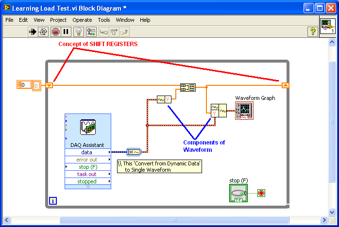
Very new to LabView, and I fight with wiring to the top of my Daq Assistant, in order for a chart data of a load cell. I have plugged my scale to the acquisition of data and you want to measure strength readings over a period of time / when I press stop. When I run my program it graphic only a finite number of readings and then clears the graph to copy the new readings on top. I put my chart outside the while loop so that it would be graphic a reading at the same time as they were read, but it does not work. If my son is not what is wrong, I feel that my time parameters for the Daq Assistant is not appropriate (and I do not know how to set those either.) I don't understand the description/effects rates and samples to read.
Thanks for your help.
AFLR wrote:
A very simple problem...
Very new to LabView, and I fight with wiring to the top of my Daq Assistant, in order for a chart data of a load cell. I have plugged my scale to the acquisition of data and you want to measure strength readings over a period of time / when I press stop. When I run my program it graphic only a finite number of readings and then clears the graph to copy the new readings on top. I put my chart outside the while loop so that it would be graphic a reading at the same time as they were read, but it does not work. If my son is not what is wrong, I feel that my time parameters for the Daq Assistant is not appropriate (and I do not know how to set those either.) I don't understand the description/effects rates and samples to read.
Thanks for your help.
Hi, AFLR,.
I think the settings are fine, you have defined DAQ to read 100 samples at a rate of 100samples per second, you will get 100 samples per second.
Now to maintain the previous data in the graph (which is not the nature of the chart), you will need to keep by writing additional code.
If you already know:
1. SHIFT registers and
You can easily implement this requirement, find the attached VI for your reference.
-
Graphical representation of the different channels separately
I'm a VI design that acquires data from 3 different channels (voltage). The data from each of these channels must be converted separately (user-defined) in other quantities (say, pressure, temp and force). Am I voltage data acquisition and using the formula with coefficients powered by user to convert the data.
However, I would like to be able to store the data of the amd chart separately. In the above procedure, the signals of all channels are under conversion. I want each channel to undergo a conversion specific and graphic and store the data for each channel separately. How can I do this? Please suggest.
Thank you
Dheeraj salvation,
The order of the signal depends on the order of the DAQ chain that you configure. I think that the signal of channel (ai0) 0th will be available in the branch above the page which is the tension in your case.
You can mark it as a solution if your problem is resolved so that others can also get help on the wire later. Do not hesitate to ask if you have more doubts.
Kind regards
Amine31
(Bravo to give good answers, mark it as a Solution If your problem is resolved
 )
) -
graphical representation of the partial circles
Hello
I create a vi that graphic a circle for a while, so, like pi/3 to 2pi. I use the sin and cos function. How would I graph these partial circles?
Thank you
CHOD
Your loop for just creates a table that has the same value N.
Take a look at this.

-
View a graphical representation of the Vista disk defragment process like XP only?
I'm looking to watch my disk defragment visually as you can in windows XP, with the red and blue lines. is it possible to raise this view in windows vista? currently I can trigger a disk defragment on place or plan a regularly, but I have no way to monitor the progress made during the process.
Vista doesn't have a graphic display just like XP.
Vista disk defrag works quietly in the background.
You need 3rd party Software for what you want:
http://www.SnapFiles.com/reviews/Auslogics-Disk-Defrag/adiskdefrag.html
Auslogics Disk Defrag is a disk defragmentation tool that supports FAT 16, FAT 32, and NTFS volumes. It defragments supply with demand automatic defrags when your system is idle and advanced options to customize the files that will be défragmentées.
http://www.SnapFiles.com/reviews/IObit-SmartDefrag/iobitsmartdefrag.html
Smart Defrag is a Disk Defragmenter automatically keeps your hard disk space does not become too defragemented, which may cause slower disk performance. It works continuously in the background while your computer is idle and requires no further user for basic maintenance intervention. The program also includes an option of manual defragmentation as well as support for the regular defrags and with optional file system optimization.
http://www.SnapFiles.com/reviews/UltraDefrag/UltraDefrag.html
UltraDefrag is an Open Source disk defragmentation tool that offers a quick Defrag, using a pilot based on the kernel. It offers a simple with a cluster map display graphical user interface, as well as command line interface and scheduling option. The program supports full defragmentation and defragmentation of space (compression) and you can include/exclude files or folders based on their name or their size. Other features include HTML reports and the boot time defragmentation. (Does not work on Vista x 64)
http://www.SnapFiles.com/reviews/Diskeeper_Home/Diskeeper.html
Diskeeper Home is a fully automatic defrgmentation engine that replaces the standard Windows Defragmenter. Built-in defragmenters are manual resource only, consuming and require full administrator privileges to operate. Execution of Diskeeper is like hiring an expert to monitor constantly and to maintain the maximum performance of your systems. Diskeeper is the fastest defrag engine ever built. National Software Testing Lab (NSTL) proven 300 to 500% faster and much more thorough than the built-in defragmenters. The program includes a unique feature set it and forget it with smart planning, which, once set, works invisibly and automatically in the background. In addition, the Frag Guard feature to avoid fragmentation in your most critical system files. Additional features include starting defrag, priority settings and the ability to defragment multiple disks simultaneously and automatically while the system is in use.
See you soon. Mick Murphy - Microsoft partner
-
graphical representation of flat data
I'm looking through the widgets that come with Flex and they seem simple. However, all examples use tables as the data provider where calculations have already been made. Data are often stored in the database in this way, so I wonder how the users here to get these types of values to put in their graphics.
The database which I use to store these data (Quickbase) is able to serve the XML in a flat structure. How could perform calculations on that data? Should I create a new table by looping through the collection of existing table? In Ruby, I used before hashes, with the index corresponding to the value on which group you. I didn't it was effective however.
For example, I am creating a graph of cumulative total of the number of recruits used per month.
Thanks for your help!
Thanks John. It's a good suggestion. I found a blog here , which seems promising post. I'll post here if I managed to do the work.
-
Graphical representation of a table
So I have a set of data (which are attached below as TEST file.txt) that is parsed into an array and I need the first column chart (abs time) compared to another column (any channel of data). I am able to get a table (columns of f2 instead of 5 with the first column being the time and the second data from a selected channel) However, I can't get a suitable to display xy chart. I changed the format of the x-axis of the chart at the time of the abs, but its still does not.
The TEST file.txt is the original data and the VI is what I use for this chart. The Subvi in the present code analyzes the text file to the table saw in my code ("analyzed data table")
means you want to draw two digital picture to existing and x y output as time stemp.
I would suggest using vi I joined.
Try and tell me that is useful to you or not.
-
Graphical representation of the difficulties
I have a Kiethley2100 and a Kiethley199 I try to use tgether to draw two curves of different voltage, HOWEVER, I am unable to get the chart to display something other than the current tension. I know it's funny formulated, the graph has a point that is located on the 0 for the time mark and moves up and down like changes in voltage, but he refuses plot points ago. I understand how to draw a line between two distinct points on the chart (line interpolation). Is there a way to format the X axis to indicate the correct time for which points were taken?
Hi strings,
It sems you are very new to LabView. So, you should:
-read the help and always light the contextual help
-check the eamples that come with LabView
-follow the (free) online courses in the University section
You can create shift registers by clicking with the right button on the edge of loops (for/all)...
-
Before I dive into a new piece of code, I would seek the advice of some cranky
I have a lot of intensity 3D... I think it is the best way to describe it.
We will have a cube with a matrix of thermocouples in various locations.
I got regarding obtaining all temperature values in a single table.
I need some advice here.
I should create a 4 x 4 x 4 table (if such a thing exists... I have no experience with anything beyond 2D)?
In addition, what type of chart/graph/parcel that you would recommend?
Thank you!
Take a look at my 3d car code. It should help you get started.
Post back after you've played with it if you still have questions.
Ben
-
Instrument i/o Assistant and graphic representation
Anyone know how to use data from an instrument of e/s Assistant entry and put it in the values of a graph y? I have problems with this, because it returns values such as '0 v' and ' v 256 "but I need just the numeric value to get a chart to work.» Any advice would be much appreciated. Thanks in advance!
Hi Rach_77,
In order to get rid of the 'v', you can use the subset of string function and set the offset to 2. This will take the first two values and give you the number. From there, you'll just have to convert the value to any type you want. I hope this helps!
Kim W.
-
Reverse an array to a graphical representation
Hello world
I am trying to reverse an array of data from a chart, however, when the array inverter function is used the data appear to be reversed only at halfway. I'm confused on why this is happening. Thanks for any help.
You will need to explain what you want this VI to do. When run with the default settings, there is only one element in the table.
Everything that you do, I'm sure that the program is far too complicated.
-
graphical representation of data in the pop up window
Hello
I would like to chart a selection of data in a pop-up window, the data are selected and produced within a vocation while loop. I would also like to be able to close the pop-up of in the pop-up, or appeal vi.
That's what I got so far, any suggestions?
Thank you
Hello
Watch attachments
-
In real time several parcels using the graphics buffer XY?
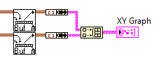
Hi all. My teacher wanted to add a second set of data to the plot in real time, I've created in my vi. I was able to trace the two sets of data, but not as two plots. I managed to add a second point of y to the plot. What is the appropriate method for the use of a buffer of xy-graphic inside a loop to draw two separate parcels?
The idea is that once I have two plots I can adjust a second axis and adapts the second group of data to this axis.
Thank you!
Nukem,
LabVIEW 2010
PS. Here is a picture of the small section of my program which is graphically representative data.
-
help understand the digital and graphical waveforms
Can someone explain to me how digital waveform working with NOR?
I did a channel physical and wired to a DAQMx create channel then I have it connected to a NSamp of 1Chan ereading Wfm DAQMx and then wired it to a graph of digital waveforms.
I put digital and graphical digital waveform playback in a loop.
When I run it, it seems to me only to get 1 sample on the graph per loop iteration.
The desired output is to add each digital sample as a function of delay which can connected and or scrolls in time to examine what is happening with the signals.
Where is my mistake?
My VI is attached.
Any help would be greatly appreciated!
Also another quick question, is there a 'comment' as a command / / c or ' in VB? Thank you.
Hi Henry,.
Thanks for the post! It seems that you are having problems with the acquisition and the graphic representation of digital data using DAQmx and LabVIEW. You are right that the type of program you have returned a single sample every loop iteration, because you make an acquisition without buffer, timed by the software. This means that the program reads a sample for each channel, whenever the DAQmx reading VI is called, which will depend on the speed of the software will run. In addition, when you view this data, the chart will only display data acquired for this iteration of the loop (that is, in this case, a single sample).
To accomplish what you want will take some extra work and overhead costs in the software, but you can essentially use a shift register and accumulate samples that your program runs. There is a practice done just VI to do this kind of thing with digital signals and is called DWDT Append Digital Signals.vi (this can be found in the palette of functions in respect of programming"Wfm Digital Waveform"). I created a small example which you should be able to run that does this. What actually happens is that the waveform is rewritten each time with new data added in addition to the data passed in. To be able to scroll back and view this data, I turned off automatic scale on the x axis (if it is enabled, it will constantly increase and tries to show all the data at the same time) and selected just a data window to display. In addition, I added a horizontal scroll bar to scroll through the review data.
And to answer your question about the code comments in LabVIEW, this can be done with a clear Structure of the diagram. You will find this structure in your palette of functions in respect of programming' Structures. Using this structure, you can select a part of your block diagram to disable and switch to the active state of wire through the or add different features that will run. Hope this helps and good luck!
-
Make a graphic interactive barcode?
Hi team,
OK maybe try to be too clever here... Where should I look to find out how... I want to do an interactive gizmo to the discovery of 20%. so I want a small cursor and a red (20%) and a green bar (80%), while when I slide the cursor to different numbers - lets, for example between 1 and 100, I get a graphical representation of 20% of the number selected as well as the real numbers? make sense? then to 50 10 40 green red column. to 100 Red is green and 20 80?
I could just have a MC with different images and select a few numbers to highlight and simulate it. (which I might end up doing) but I would like to know how to do this dynamically if you guys can point me in the right direction.
See you soon
void
A very simple method is just to draw a green rectangle of 80% and 20% of red. Make a movieclip. Then, you can simply change the scaleX or scaleY property of the movieclip to make its length or height corresponds to the selected number. The ratio of red to green change, just the selected number.
Maybe you are looking for
-
Recommendation of the DVD ripping software
Hello, can anyone recommend a good software for Ripping of DVDs to create high quality for editing files? I can pay for the software if it is not free software. Thank you!
-
How to enable the memory of text when you fill cells
When you use numbers, you get suggestions based on what you have typed before. Has anyone found, whether there is a way to disable this option? If so, please let us know.
-
Re: How to save BIOS of Qosmio X 75 - A7295?
Please inform me how to save the PC BIOS laptop Toshiba QOSMIO X 75 - A7295 Thank youJasim
-
can not backup windows because: Backup has encountered a problem during backup of the C:\Users\marcel\Documents\Youcam file. Error: (the system cannot find the specified file. (0 x 80070002))Backup has encountered a problem during backup of the C:\Us
-
OfficeJet 4500 G510n - the carriage does not move to the right
Operating system: Win7. Chronic problem - when I need to replace an ink cartridge, open the access door fails to stimulate the transport to move the location of the far right cartridge replacement. Usually solved in electric bicycle and try again, u