Gaussmeter Hall effect
You can use the separate keys. To be sure that only one button at a time, you must use local variables or property nodes to reset the other.
I personalized the radio button for more like your Panel. The option button has "both a key" function built in, you don't need to program it yourself. You could make the invisible frame by using the tools of coloring.
Lynn
Tags: NI Software
Similar Questions
-
Hello
I use a 90217 Melexis Hall effect sensor and magnet to measure the speed of ROTATION of an axis of rotation. I have developed a VI in LabVIEW for this purpose. It measures the speed of the rotation axis with precision up to 600 rpm. The problem I have is that whenever I have to turn the shaft at a speed higher than 600 rpm, all measures of my VI is 600 rpm. For example, the tree turned to 1100 rpm and all that he read was 600 rpm. I tried to fix this by multiplying my rpm of reading by a factor of 2, and I had always a 1080 RPM reading when my tree turned to 1100 RPM. However, I wanted to know if there is an error in logic that I used for my VI. Thank you.
Hi SS1,.
two points:
(1) your inner loop is not necessary:

Use rather math table...
(2) sampling frequency is set at 1000 Hz. According to Mr. Nyquist your highest possible signal frequency is 500 Hz (in theory). You are limited by the sampling frequency...
-
Need to display the speed of speed Hall sensor SIgnal
Hi all
I have a speed Hall effect sensor. I'm observing the signal of the sensor to LabView via NI DAC USB-6008. Could someone please help me in the design of a logic that allows to display the wheel on Labview speed according to the reached the sensor signal? It will be really helpful if someone can come up with logic.
Thank you very much in anticipation
Sorry, that was the bad VI.
It's the good VI:
-
Amnesty International and counter sync + USB signal stream (USB-6210 vs USB-6341)
Hi all
I'm at a stage of identification of a material suitable for the following tasks:
- 5 analog inputs (AIs) of reading at the same time, tensions at a rate of kSps (at least) 10,
- application captures 2 inputs using timers (detection of contours with timestamps), square wave entry with duty ratio of 50 percent and about 1.5 kHz frequency and variable pulse width / frequency (from 2 sensors hall, representative of the DC motor rotation speed and direction, quadrature signals), resolution of timestamps should be (at least) 50 ns,
- AIs and counters should behave in a deterministic way, and must be synchronized in a way,
- data to be transferred via the USB port of a host computer with Matlab Data Acquisition Toolbox (unfortunately not LabVIEW).
I've identified the long USB-6210 USB-6341 and potential candidates of material to accomplish the above tasks, but after reviewing several documentation and the topics of the forum, I'm still a bit confused, if both are fully working and my approach described below is not working properly.
Counters: I intend to use the internal time base available 20 MHz as being the source of meter to get into account the resolution of timestamp 50 ns. External impulses hall are used as sample clock (about 1.5 kHz, see above). As the pulse width varies, the sample clock is not constant.
AIs: Using a 10 kHz internal clock signal derived from the time base of 20 MHz for timing and analog inputs (trigger) start-up and counters simultaneously material should translate into the required synchronization and deterministic behavior.
It work? Other recommendations?
Next is the USB data transfer: all HAVE 5 and 2 data entry of the meter must be correctly transferred to the host computer (the corresponding rates are shown above). USB-6210 is capable of 4 USB signal flow, device USB X range (6341) offers 8 of them. Unfortunately, I could not understand the exact meaning of the expression "signal flow" still. Do I need 1 flow of input signals (would be 7 for my application described) or 1 stream for all analog inputs and 1 for counter inputs (lead 2 streams for my request). Is there no further details on this approach (more than Streaming of signals of NOR) USB signal flow?
Any challenge to the described application that I might have forgotten? 6210 USB seems to a very limited number of entry PFI, maybe even too low for my meter participate application?
Looking forward to your comments and advice.
Concerning
jAwA
1. I recommend the X-6341 series on the M-series 6210 sake of counters/timers. It is more of them, and each of them is more capable. It can also have a great FIFO embarked for meters that may be important in certain tasks, although I don't think that you currently deal with one of them.
2. your general concepts on timing & sync are satisfactory. You will be able to share and to route signals that help ensure synchronization and determinism between the timestamps for your various tasks. Note that for meter entry tasks, you need set up the trigger 'Arm Start' rather than the regular start trigger.
3 is not authoritarian, but I believe that the flow of signal # will correspond to the tasks #. For you, it would be 1 task of HAVE and tasks CI 1 or 2. (Not clear if you have 1 Encoder with 2-channel quad that would require 1 task of CI, or if you have 2 encoders with 4-way quad).
4. pay attention to the hall effect signals that are not virgins. Digital filtering is available and probably better on the X-series, the series M.
5. strictly speaking, edge detection is a type of digital input task that produces samples but no timestamps. Ideally, I would like to parallel wires on the two digital inputs for the entries of detection and counter change to position quadrature decoding. Then I would sample the counters Encoder 1 or 2 using the internal pulse 'event of detection of change '. I would create another counter timestamp change detects pulses as well.
-Kevin P
-
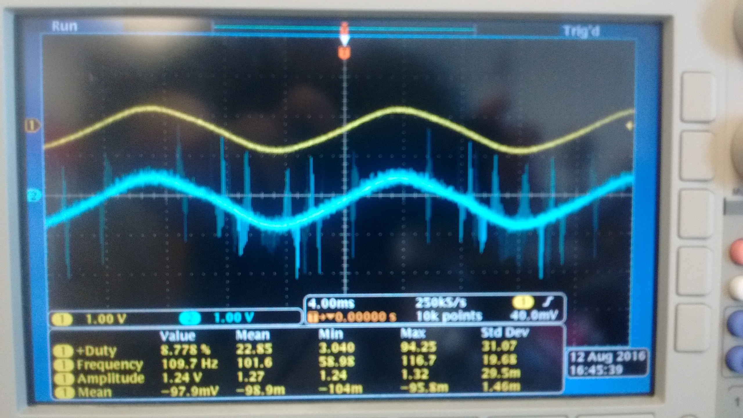
I currently use a NI 9215 module with BNC terminals to read the outputs of two different types of voltage sensors. Probe is a probe differential o-scope (Tektronix P5200A) which has a rejection of sound very good, while sensor B is a shunt isolated hall effect measurement using a LEM lv20-P and a custom PCB, which has a considerably lower noise rejection. Noise in the circuit to be measured is mainly the result of a H-bridge Inverter circuit that goes to 10 kHz. A picture of two sensors measuring the same signal displayed an o-scope is shown below with the sensor signal on top and B sensor on the bottom.
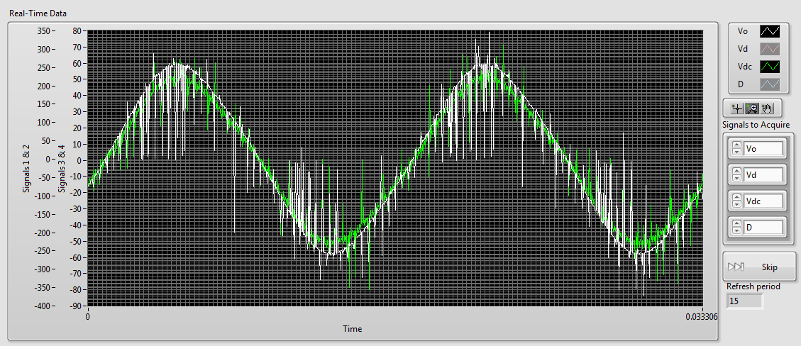
As you can see there is a lot of noise in the B sensor while sensor A is most often silent. When I connect then both of these signals to my NI 9215 I get the signals shown below (75 kHz sampling rate), sensor A appears in white and green B sensor (ignore the differences in scale, it's programmatically).
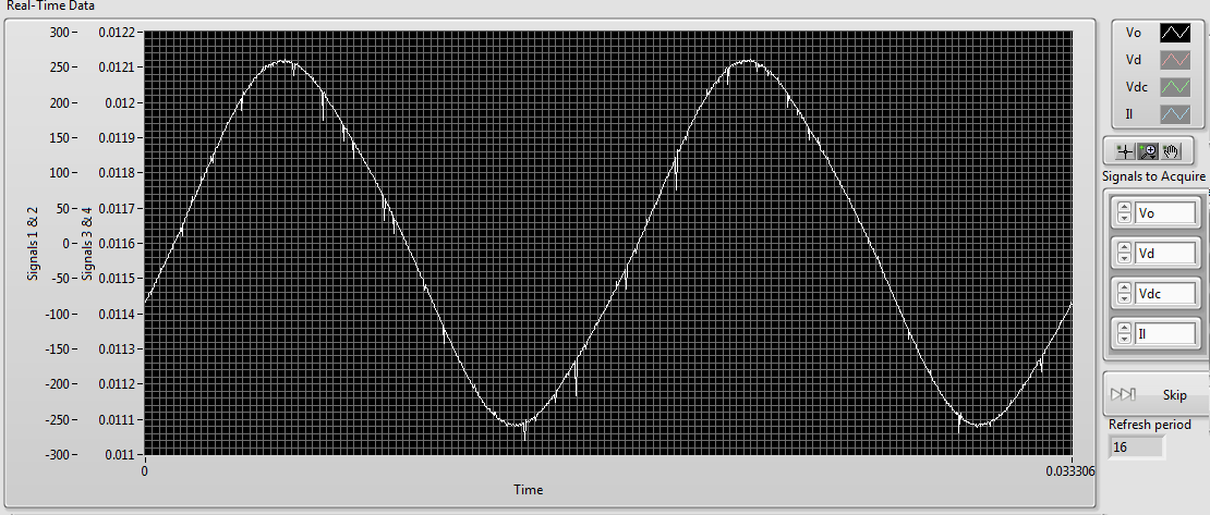
As you can see the noise level in the two now is comparably high. However if disconnect us the 9215 B, the signal from the probe sensor then replaces the image below:Although there are some present noise, the signal is much cleaner than before. The natural conclusion that I draw from this is that there is significant interference between the two signals. The same wiring is used for connecting to the 9215 as o-scope, and the two sensors use shielded twisted pair cables. This amount of crosstalk seems very high compared to the - 80dB listed in the specifications of the 9215. Any ideas what could be the cause, or how to fix it? Unfortunately, I am currently unable to afford a second sensor A.
1. by the impulses of the runt, I was meaning extremely short pulses on A sensor. If they are short enough, you will not see them unless you are looking for.
2. my concern is whether the switching noise is contaminant entering your power supply through the electric wiring. Of course, good feeds should filter this point, but it's just another thing to check.
3. the quick and dirty way would be to use a BNC T-connector to connect the oscilloscope and the ground in this way.
Suggestion of ferrite chokes on instrumentation Henrik is a good.
I understand that this type of inverter using the load (normally three-phase current motor alternative) to filter the frequency of bridge (10 kHz in your case) to the required frequency (normally 50 - 60 Hz). This means that high frequency currents go all the way to the motor, if they are not filtered by the cables first. You can not just screen the housing of the inverter, because the currents of high frequency down to load part of its operation. If you start testing things, you will all the way from the inverter to the load of the screen and will be impossible to Rodez to meet your instrumentation.
Standard WARNING: If you are tempted to connect directly to the UPS output and reduce until the input voltage range 9215: first of all, make sure that a qualified person has verified your wiring. Second place of fuses in all lines near where the tension is taken offshore. A UPS maybe a current loophole in the beach A 100 and you don't want that to the bottom of your wiring of instrumentation. Not directly relevant to your ad, but I feel that I specify.
-
With the help of the meter from 6525 to measure the frequency: is there a more orderly way?
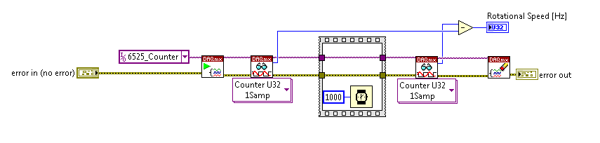
I am currently using the high speed on a module USB 6525 meter to measure the frequency of an object in rotation via a sensor hall-effect.
I was wondering if there was a simpler way / more effective this encoding than that?
Everything that I currently perform the current meter reading, wait a second, take another reading, and subtract one from the other. The result is the frequency in hertz.
Is there a way to get the 6525 to return the number / change County after 1 second?
Thank you
On the 6525, you have a country of the event and you can't make a measure of frequency.
-
After the search and read a few posts from forums, I understand using the sequence is probably not the best idea?
I wanted to get some advice on the best way to address my problem.
What I want to do:
I intend to use the van der Pauw method and the hall effect to experimentally determine various parameters for a small sample of semiconductors.
Right now, it's a lot of your time to make all of the BNC connections required by the hand that in all the totals to 24 or 48 connections to make.
To speed up the process, I want to use Labview to control a microcontroller to control transistors which controls of the Tower relays who make the required connections. At the same time after each series of necessary connections have been made, a current source controlled by Labview must provide the necessary current, a voltmeter to read voltage. A total of six different sets of four connections to perform and voltage read for all six groups. This must be done twice, but since the equipment creating the magnetic field is controlled manually, I can just run the program twice.
Recently, I learned how to control an arduino using labview and how to control the power source and the voltmeter using labview as well.
So here's the sequence that labview should send orders:
Digital I/o using 6-pin on arduino
1. initially, all pins are attached below.
2. first pin set high, while the rest remains low. This option turns on a transistor making it the first series of connections.
3. the current source is turned on and provides a specified amount of current to the sample.
4 voltmeter measures the induced voltage and stores this as a double or be it in something like a table.
5 current source turns off.
6. second pin on arduino set high, while the rest low and steps 3 through 5 are repeated until all 6 pressure measurements were recorded.
7. the 6 measures must be exported to excel the file or Notepad or other.
8. the same data could be transmitted to something like a different tab in the same program to perform the calculations to find the semiconductor, parameters of the sample.
So now my question on the best way to do these things. I was looking through labview and found what is called a sequence of flat, but according to the forums it's supposed to be frowned upon.
My other thoughts using some kind of combination of loops/case, but I'm not sure how to structure and what should be included or excluded from the loop. Other thoughts are maybe a timed structure. Another possibility is to create 6 different vi and calling it one by one.
So basically the program run, and once completed, I need for each measure 6 voltage, preferably displayed in both a table and saved in excel/Notepad.
SaintsFan says:
So here's the sequence that labview should send orders:
Digital I/o using 6-pin on arduino
1. initially, all pins are attached below.
2. first pin set high, while the rest remains low. This option turns on a transistor making it the first series of connections.
3. the current source is turned on and provides a specified amount of current to the sample.
4 voltmeter measures the induced voltage and stores this as a double or be it in something like a table.
5 current source turns off.
6. second pin on arduino set high, while the rest low and steps 3 through 5 are repeated until all 6 pressure measurements were recorded.
7. the 6 measures must be exported to excel the file or Notepad or other.
8. the same data could be transmitted to something like a different tab in the same program to perform the calculations to find the semiconductor, parameters of the sample.
A state machine with these 8 States (and perhaps some assistance States: idle, stop, start, error, etc..).

Basically a while loop with a case structure (one case for each State) and a State (e.g., enum) variable in a passage that. Look at the design templates provided with LabVIEW.
(A flat sequence is too rigid for this. What happens if an error occurs in the #5 State? It has no way to go to a State of emergency. What happens if you want to stop in the Middle? What If a State fails and must be repeated.)
-
Has anyone ever used a Hall sensor to measure the speed of the engine and crank angle? I'm trying to understand how to measure the lunatics of angle of a single cylinder engine using any data acquisition system. I just need to know what settings or VI is used to translate the output of a Hall effect sensor data into freaks of angle in degrees. I have a 35 teeth wheel, attached to the motor shaft and the installed sensor just in front of it, so I'm 35pulses / revolution. I guess my question is how to manipulate the impulses that I enter freaks of angle in degrees? Do I go about it as an incremental encoder or can I use your extraction, etc. Any suggestion will be appreciated. Thank you.
Thank you Rob, but I already found this earlier; I guess I would have deleted the post. I have a speed of 36 teeth removed a tooth to serve as an index (by aligning it with the TDC marker on my wheel engine) so that every time my sensor generates a long pulse corresponding to the 3 valleys (Valley-missing-tooth-Valley), indicating my TDC in any revolution. That, as well as my engine speed data, makes it easy to calculate the interval of angle freaks (which varies according to the engine speed). In addition, the hall effect sensor is not output a digital signal. It's an exit proximity sensor an analogue signal which corresponds to the teeth and valleys on speed, so the signal takes the form of a digital square wave essentially, but is not actually digital. According to your power supply, you get exactly 0 and 5, you get 0.1ish and 4.7ish values that simulate a waveform still, so a module of analog input on the compactrio (which is what I use) would work very well. However, thanks for your response.
-
wave shot through of shunt dc motor
Hello
We have an application where the positive of a power source is connected to a shunt and the other end of the shunt is connected to the positive DC fan engine.
If a CRO is connected through the shunt, it shows a sine wave form. We want to replace this CRO with Labview software that allows to capture this waveform for analysis more away from ingredients using some materials preferably a USB based. We have labview 2009 version running on windows 7, 32 bit.
We are not sure if the material can be used since the motor is inductive and as soon as the power is turned on, it gives a peak. So we need assistance regarding if any material OR can be used directly in the system.
Thank you
Rohit
An important consideration is that these systems is the possibility of ground loops. The mass of the engine system and patterns of DAQ system can have enough impedance current heights in the engine, mainly because of defects, can cause enough voltage difference damage the measuring equipment or disrupt the measures.
Very rarely a direct connection to a shunt resistor is a good idea with loads of engine.
Consider using an isolated DAQ of entry device, an amplifier for instrumentation isolated between the valve and the data acquisition system or a single Hall effect current sensor. I used the devices of the series Allegro Microsystems ACS (> 2 kV isolation) on a few projects.
Lynn
-
Hello
I am currently working on a Senior design project where I have to measure rpm, torque, pressure and temperature. I use strain gauges, pressure sensor and a Hall effect sensor, thermocouples for these readings. A myDAQ collects readings rpm and pressure while a cDAQ collects couple and readings of the temperature with NI 9211 and NI 9237 modules. I have created LabVIEW screws for each sensor and they work. The problem I have is when I try to create a VI with DAQmx who reads all the values of these sensors simultaneously. The VI I joined randomly displays one of the measures while other measures remain empty. How can I change my VI so I can show all my readings at the same time?
Yes. Create multiple tasks, where all the strings that are common to a specific device are grouped in the same task. Then go and run these tasks in parallel. Do you need a precise synchronization between the tracks in the different devices? If this isn't the case, then the method should work perfectly. If you need a precise timing, things would get more complicated, but might not be impossible.
-
How to measure/estimate bias of the signal
Dear Sir
I play the FFT of the signal that collects in real time of the hall effect current tranceducer SCT-013-005. I need to measure/estimate bias of this signal. Can you please guide me how I can do it. (My vi which is developed in LabVIEW 2012 is attached)
I'll be grateful to you for your attention and consideration.
Kind regards
Urfee
Hi tronoh,.
What about using the function 'Basic average DC & RMS' on your periodic signal?
-
How to do like a hall of mirrors effect
Hello, I want to use an effect in a video like the one used in the "Zlad - Elektronik Supersonik" http://www.youtube.com/watch?v=lp_PIjc2ga4 video (15 seconds in the video) which is a bit like a Hall of mirrors or type infinate echo effect. The video that I use is almost identicle to that one, but instead of a person on a keyboard in front of the green screen, he's a drummer in front of a green screen. I tried to play with the echo effect but was not able to get the same type of effect. Anyone have any ideas on how to do it? Thank you. =-)
The Echo effect works on the displacement of the pixels. It is based on time, not position. If you player is essentially standing still, you won't get anything that resembles the effect above. You can get this effect by moving the entire layer, before dialing, then application of Echo to the demo.
If an item is located in the upper right of the first image and in the lower left corner in the 10th and you apply echo to the layer with the right settings you will have a bunch of copies of the layer as part of 10th that show all the posts between frame 1 and 10 (IOW 10 images). If the element is not between 10 and 20 at the time wherever you get the last frame you'll only a copy of the visible element because pixels will not be moved to the last 10 frames. With the help of echo on your drummer, you would get a lot of time with echoes of her arms move, not a bunch of images of the drummer as a Hall of mirrors. IOW, you see 10 arms, 10 drum sets.
Here's what I'd do with a drummer who basically is stationary. First of all, I would like to make the layer to a 3D layer. Then, I would apply this expression to the position property of the layer.
inc = index * 20;//each layer offset 20 pixels
x = value [0] - inc;
y = value [1] - inc;
z = value [2] + inc;
[x,y,z]
The expression is quite simple. The first line defines a variable called Inc., bringing the number of layer (index) and multiply that by 20 pixels. The next three lines takes the value of each variable position of a 3D layer and modifies the value of the increment 'inc '. I subtracted 'inc' of X and Y to move the image up and to the left, and add "Inc." to the value of z to move the layer to the camera.
The last step is to duplicate the layer as many times as you like echoes. You could bind the "Inc." for a cursor of expression on a layer draw so you can animate the offset.
If you want the movement to echo that you would simply sequence layers so that each starts a frame or two after the first. This is what has been done in the example of youtube. The image was offset in X Y and Z of the space (or scaling), then the start time of each layer has been moved so that the mobile arm seems to follow the movement of the arm creating a wave of stage effect.
I hope this helps.
-
Need advice on the sound effect.
Hello
I have a small production recorded inside on green screen. After the seizure of the thing, it is supposed to look as if the talent is standing outside talking.
Is there a way of hearing CS6 to put on a filter / effect to make the sound more "outsidish"?
Thank you.
Ulf
Well, the thing with 'outside' is that it is usually the most, dryest acoustic, you can imagine. Unfortunately, it is easy to add various reverberations of room sound atmosphere - but darn almost cannot remove a sound room ringing hollow, if it has been registered like that. So the question is: did you close enough that the noise from the Hall is not a problem with the microphone?
In any case, instead of a filter, what I would probably do this is add a loop of some outside noise. That's exactly what it would depend on your background, but even a few song light wind/bird/cars driving by / waves on the sea, or anything that could help with the illusion.
If you don't have your own collection of outdoor environments, I can recommend http://www.freesound.org as a source of excellent (and free). Just search for 'atmosphere garden' or 'atmosphere of the forest' or whatever and you'll have plenty of choice.
-
How to eliminate a brilliant on the face effect
I would be grateful a tips on how to eliminate this effect, shining on the face of this actor

Makeup artist 3 filter Softworks Sheffield ($100), available for FxFactory.
Perfect skin was completely written from scratch. With the new algorithms of smoothing (including one for addressing the black spots and dark spots), refined selection techniques of the skin (with a new control interface on the screen with the possibility of areas of the mask of the screen) and a feature of the skin with the size, lighting, texture and depth controls, perfect skin is the cornerstone of any beauty Kit.
-
Just download the latest version of the software, and the new effect of bubble in the messages seems not to work. Tactile 3D works well, but does not appear in messages
Check the settings > general > accessibility and make sure you have Motion cut off.

Maybe you are looking for
-
How can iCalendar subscription I cancel a subscription on my iMac and iPad?
I have an iMac (2008) running on el Capitan. In the iCalendar app, it seems to be a subscription to the calendar of Canadian holidays, which I did not need. I tried to delete these, but get a message on the screen telling me that I can't delete item
-
Name USB - HDD internal variable? PX1223E - 1 32
Hi allmy new USB HDD (Toshiba PX1223E - 32 1) is connected to my router. Access by ftp is not possible without problem, because the name "internal" is TOSHIBAUSB3-5 - HARD drive - the $ $"""-quotationmark''is not allowed - but I can not change the na
-
Need help updating the firmware on a Designjet T770 44 inches.
Hello I just bought a 44 inch Designjet T770. I had some small problems of implementation as the inks were obsolete, and a print head needed replacing. They have been sorted and now it seems to work properly but always tells me that I need a firmware
-
Wallpaper Windows 7 stuck on "stretch"!
Hello world I know it is an extremely important issue, but it seems that no matter how many different ways I try to toggle the settings of my wallpaper of "stretch" to "adjust" or "mosaic" or any other option, it always comes back to the back to stre
-
I would like my year 10 students design and create simple mobile Web sites
I would like my year 10 students design and create simple mobile suitable sites that can be used on mobile devices. The idea is that they design the site for their chosen idea and then be able to test this on their own mobile phones or their friends.