generation of digital, analog signals read snap SMU-6358
I have two SMU-6358 card and I want to send control signals to my camera and read the analog signals from the device with them.
For the digital control signals, I tried to set up a system where I specify the identifiers of the pins, bring them into arrays of strings - the respective waveforms would be collected in the tables too - and I transfer them to a VI of inputs/outputs multiples that puts digital waveforms for the cards output pins.
I developed this code here, but it doesn't seem to work. I can't understand how I can convert the string and form table wave to meet the requirements of the input/output VI or which another VI I could use to do the job. Or is there a smarter way to do it?
Thank you
Kriváň
Dear Kriváň
Please find attached the VI in LV 8.6 format. Also, I HIGHLY recommend to rearrange the front panel and which makes it neater, your code is very hard to read and not structured at all. I hope this helps!
Tags: NI Software
Similar Questions
-
How to convert an analog signal into digital signal
Hello
How to convert an analog signal into digital signal, such that each sample of the analogue signal corresponding to 1.2V will be represented as '1' digital signal and other samples of the analog signal (which are not 1.2V) will be represented (converted) ' 0' in the digital signal.
And how to view the wavefroms or graphical indicators signals.
Thank you.
If you have 1000 samples and you want to convert to digital, you get 1000 digital values. Attached, that's what I mean.
-
Reading of analog signal using DAQPad-6016
I'm reading an analog signal using DAQPad-6016. An entry is on the ground, the other is Vdc. I can't operate at MAX and I'm confused becaue MAX alone gives me an option for differential reading, but the list of pins give enough information on how to connect in a different way. Is there a reference as well?
Hello, Bernadette.
This link should have what it takes to equip themselves properly: http://www.ni.com/gettingstarted/setuphardware/dataacquisition/analogvoltage.htm
After that you have put work in place, specifically see step 11 for check the connections of the device.
I hope this helps!
-
read the analog signal 0-10 volts of NI6123
I'm reading the analog signal of NI 6123. The range of the analog signal is 0 to 10 volts. This works well when the signal voltage is 0 to 5v (0 ~ 32767). But when the signal is 5 to 10 volts, the value read is always 32767. I also tried the different reading function: DAQmxReadBinaryI32, DAQmxReadBinaryU16, DAQmxReadBinaryU32. The value is identical to DAQmxReadBinaryI16. My OS is windows vista. Here's the part of my codes.
**************************************************************************************************************************************************************************
Create analog data tasks.
DAQmxErrChk (DAQmxCreateTask("",&datHandler));
DAQmxErrChk (DAQmxCreateAIVoltageChan(datHandler,"Dev1/ai0:7","",DAQmx_Val_Cfg_Default,-10,10,DAQmx_Val_Volts,NULL));)
DAQmxErrChk (DAQmxCfgSampClkTiming(datHandler,"",RATE,DAQmx_Val_Rising,DAQmx_Val_ContSamps,RATE*MAXLAS));
DAQmxErrChk (GetTerminalNameWithDevPrefix(datHandler,"ai/SampleClock",trigName));
Create counter tasks.
DAQmxErrChk (DAQmxCreateTask("",&ctrHandler));
DAQmxErrChk (DAQmxCreateCICountEdgesChan(ctrHandler,"Dev1/ctr1","",DAQmx_Val_Rising,0,DAQmx_Val_ExtControlled));
DAQmxErrChk (DAQmxCfgSampClkTiming(ctrHandler,trigName,RATE,DAQmx_Val_Rising,DAQmx_Val_ContSamps,RATE));
DAQmxErrChk (DAQmxRegisterEveryNSamplesEvent (datHandler, DAQmx_Val_Acquired_Into_Buffer, SPLEEN, 0, EveryNCallback, NULL));
DAQmxErrChk (DAQmxRegisterDoneEvent(datHandler,0,DoneCallback,));
Start the task.
DAQmxErrChk (DAQmxStartTask (ctrHandler));
DAQmxErrChk (DAQmxStartTask (datHandler));
In the call back function:
DAQmxErrChk (DAQmxReadBinaryI16 (datHandler, SPLEEN, 3.0, DAQmx_Val_GroupByChannel, data.laser, MISS * MAXLAS, & (data.dataRead), NULL));
DAQmxErrChk (DAQmxReadCounterU32 (ctrHandler, SPLEEN, 3.0, data.counter, SPLEEN, & (data.ctrRead), NULL));
write data to the file.
data.cfile.Write (data.counter, sizeof (int32) * RATE);
data.cfile.Write (data.laser, sizeof (int16) * RATE * MAXLAS);
**************************************************************************************************************************************************************************
Thanks in advance
To make sure that your device is working properly, I recommend first to test the entry in measurement and Automation Explorer (MAX) analog. You can test your device by right clicking on it in the configuration tree and selecting test panels. See if you acquired signal 0 - 10V as you expect. The next step would be to try one of the sample programs that perform a task of analog input. These examples can be found in the start menu > programs > National Instruments > NOR-DAQ > text based code supported. Try an example that does an analog input continues and double bed (instead of binary data not adjusted).
Your program looks good at first so I found nothing that stood out. However, one thing to check is if your function generator (or signal source) expects a 50 ohm or high impedance. This could cause reflections of the signal and cause the device to possibly read a voltage of half of the desired value.
-
Generation of the trigger (or TTL) analog signal
Hello world
Well I look at the droplet, riding on the vibrating bath. In this case I have to synchronize the device with the accelerometers.
Accelerometers are connected to the vibrating plate vibrating sinusoidal with frequency of 80 Hz. I am the acquisition of acceleration using NOR-DAQ USB 6212. A camera (Camera Link Basler, NI PCIe-1433) is used to acquire images of the vibrating plate. The frame rate of the camera is 20 Hz which controlled by external signal (TTL) or camera attributes.
I would like to generate a trigger of data acquisition (signal HAVE) to the camera at the first minimum acceleration in the attachment. I've also attached the file vi. Could if it you please let me know if is there anyway we can generate the trigger of the analog signal.
See you soon
NGO
Hello, NGO,
Can you post the update VI?
-
Simultaneous digital writing and reading w. measurement interval
Hi all
For the last couple days, I've been trying my brain trying to get a program to run.
I am trying to generate a camera digital 4 output bits then simulatanously count edges mounted on its LSB up to an arbitrary number set by the operator of the program, how the program should be a measure.
I note, however, that, on a certain edge County number growing (~ 950 or almost), the program crashes. The problem persists even when I remove the function that reads the LSB, although, in this case, accidents occur to a much higher number. What could cause this? Is there a way I can work around this problem?
Here is my code:
arraySizeInBytes2 = 8
bufferSize = 255ReDim readArray (arraySizeInBytes2)
publicLifetime = 100' use this to control the duration of the task takes
numSamplesToWrite = 10 * publicLifetime * numSample * 5
numSamplesInArray = 5 * 10 * numSample"the code that sets the analog and digital output signals
j = 0
k = - 1
<>
If SampPerCycle Mod d = 0, then k = k + 1 other k = k
For m = 0 to 3
If ((k) and (2 ^ m)) = (2 ^ m) then writeArray (m, j) = 1 Else: writeArray (m, j) = 0
Before m
j = j + 1
LooppublicStatus = DAQmxCreateTask ("", taskHandleDigitalOut)
publicStatus = DAQmxCreateTask ("", taskHandleAnalog)
publicStatus = DAQmxCreateTask ("", taskHandleDigitalIn)
taskIsRunning = TruepublicStatus = DAQmxCreateDOChan (taskHandleDigitalOut, "Dev2/port0 / line0:3","", DAQmx_Val_ChanForAllLines ")
publicStatus = DAQmxCfgSampClkTiming (taskHandleDigitalOut, "Ctr0InternalOutput", # 1000000, DAQmx_Val_Falling, DAQmx_Val_AcquisitionType_FiniteSamps, numSamplesToWrite)
publicStatus = DAQmxCreateAOVoltageChan (taskHandleAnalog, "dev2/ao0","",-10, 10, DAQmx_Val_VoltageUnits2_Volts, "" "")
publicStatus = DAQmxCfgSampClkTiming (taskHandleAnalog, "Ctr0InternalOutput", # 1000000, DAQmx_Val_Falling, DAQmx_Val_AcquisitionType_FiniteSamps, numSamplesToWrite)
publicStatus = DAQmxCreateDIChan (taskHandleDigitalIn, "dev2/port0/line7", "", DAQmx_Val_ChanPerLine)
publicStatus = DAQmxCfgChangeDetectionTiming (taskHandleDigitalIn, "dev2/port0/line7","", DAQmx_Val_AcquisitionType_ContSamps, 8 "')
publicStatus = DAQmxWriteBinaryI16 (taskHandleAnalog, DACwaveFormSize, False,-1, DAQmx_Val_GroupByScanNumber, buffer (0), sampsPerChanWritten, ByVal 0 &)
publicStatus = DAQmxWriteDigitalLines (taskHandleDigitalOut, numSamplesInArray, False,-1, DAQmx_Val_GroupByScanNumber, writeArray (0, 0), sampsPerChanWritten, ByVal 0 &)publicStatus = DAQmxStartTask (taskHandleDigitalIn)
publicStatus = DAQmxStartTask (taskHandleAnalog)
publicStatus = DAQmxStartTask (taskHandleDigitalOut)
publicStatus = DAQmxStartTask (publicCounterHandle)r = 0
< (publiclifetime="" *="">
publicStatus = DAQmxReadDigitalLines (taskHandle, 1, 5, DAQmx_Val_GroupByScanNumber, readArray (0), arraySizeInBytes2, SampsPerChanRead, numBytesPerSamp, ByVal 0 &)
If publicStatus = 0 then r = r + 1
If r Mod publicMeasurementInterval = 0 Then ' measure Code here
LooppublicStatus = DAQmxStopTask (taskHandleDigitalIn)
publicStatus DAQmxWaitUntilTaskDone = (taskHandleDigitalOut - 1).
publicStatus = DAQmxClearTask (taskHandleDigitalOut)
publicStatus = DAQmxStopTask (taskHandleAnalog)
publicStatus = DAQmxClearTask (taskHandleAnalog)
publicStatus = DAQmxStopTask (publicCounterHandle)
publicStatus = DAQmxStopTask (taskHandleDigitalIn)
publicStatus = DAQmxClearTask (taskHandleDigitalIn)
taskIsRunning = FalseThank you.
You were right: it was a buffer overrun. I was using integers when I should have used doubles.
Thank you for your help.
-
How can I use my PXI-6115 meter analog signal trigger to generate pulses of frequency
I work on a PXI-6115 DAQ card and want to using the analog signal to trigger the counter it's generating frequency pulses. The manual says the analog trigger is supported, but I can't use an analog signal to trigger the start of work, in the test, I use the counter 0 to generate pulses and use the signal input port analog trigger PFI 0, can someone tell me what it is? My test VI. & error message appears in the attachment.
Best regards
If you read the error you can see digital triggers are the available trigger only when you use the output of the counter.
You can work around this by setting up a dummy analog input task which will trigger an internal digital triggering when he sees the right analog trigger.
See this thread for more details:
-
G20-120: how to choose digital airborne signal to Qosmioplayer?
I have a G20-120 with analog/digital TV tuner.
I now wish to leave the DVB - T tuner to receive airborne television signals. (Try mine with analog signals only)
I can't find how? Any person who knows or who succeeded with that?MODIFIER
Hello
It would be very interesting to know what version of the Qosmio player you have.
I found this official document to support Toshiba:
http://support.toshiba-tro.de/KB0/TSB6101A90000R01.htmThere, I found information that 4.3 Qosmio player and older Version does not support the DVB - T signal.
The DVB - T signal can only be used in the Microsoft operating system -
Hi all
I'm still new to LabVIEW, but I played a little enough to create a simple analog signal generator. Product signals appear staircased when displayed on an oscilloscope, but are smooth, when I read the signals in an entry (as shown by the graph on the waveform) analog. How can I change my program settings so that I can see this staircased signal?
I run LabVIEW 2010 and use a data USB X Series multifunction acquisition.
Thank you
-Olivier
-
digital analog arm start several triggers
I trying to find out if there is a way to arm a trigger of labview to an analog signal and then actually have the trigger start from a separate, digital or analog signal. Both signals came on 2 different channels simultaneously. Research on the forums, I found that the opposite situation is possible: arm with a digital signal, then start with an analog-to-digital trigger but I have not found a way to either arm or take essentially the AND logic of the triggers two separate channels (with being analog and the other being is) as being the "ultimate" relaxation Any help/advice is greatly appreciated.
Hi, Bill Clinton.
I think you are looking for the Signal VI to export. It can be found on the pallet of NOR-DAQmx. I've also attached a document with additional information on this VI.
http://Digital.ni.com/public.nsf/WebSearch/a099c37789aacee386256e35007338e6?OpenDocument.------
-
How to create an analog signal of a text or a binary file?
I'm trying out an analog signal of a file on a map of NOR-DAQ 6251 with labview 8.5. I found examples on the construction of a waveform, but I'm stuck at how read a text file and do a 1 d table to enter my amplitudes in the buildwaveform.vi and I can't find all the information on how to do it. Help or direction is appreciated.
Thank you
David
What if all you want in the file corresponds to the values of Y, then a text file with a value on each line can be read. Read from a usable spreadsheet file. It will return a 2D you can then use array index to get a column or if you select Transpose, the array returned by 1 d would be used.
If you want to create an example, use a 1-d array constant in a VI and pass it to the writing on a spreadsheet file.
-
Output of different analog signals through 4 outputs
Hi all
Exit 4 different analog signals from the PCI 6711 map: I need help. I intend to use the waveform function from the palette of analog generation vi. My goal is to be able to enter the 4 necessary functions, it sampling information and then leaving four available analogue outputs available to the Board of Directors. I saw the code example for the output on multiple lines, but it doesn't seem like he is able to create unique waveforms through the exits, they are all the same waveform. I've attached what I thought work, but I can not get my number of rows in the data to match my number of rows in the task.
Specifically, choose instance polymorphic Analog-> multiple channels-> multiple samples-> 1 D wave.
Your current instance you chose is for just a single line.
-
Problem when the PWM signal combinning and analog signal TOGETHER!
Hello everyone,
first I DAQmx 6212, and I need to run the water pump small (9V - 16V) that should be driven by a PWM signal; I also have a motor (5V - 13V) for a water supply which must be controlled by an analog signal and it has built in a force feedback potentiometer, I logged onto this potentiometer correction + 5V the DAQmx and used the output voltage of the third extremety as a value to diagnose to know the position of the engine.
My VI shows:
1 is a normal meter production to create my PWMout signal.
2 is an analog input, I use it as a PWMin to the LabVIEW to diagnose what is happenning in my pump water through the cycle and frequency.
3 is an entry of the third extremety of the analog potentiometer.
4 is an analog output that I used as power supply of the motor valve and I used an AC/DC amplifier for aplify signal the DAQmx and the motor road, between the two (3. 4.) I made a comeback with a few calculations, I had a P-controller to know the real position of the engine valve.
My problem:
When setting to 1. and 2. in the same VI only, I get an own PWM output with no problem.
also with 3. and 4. in the same VI only i can control the motor valve without any problem.
but when I put all these 4 set found in the attached VI, I have a problem as the engine valve turn continuously without stopping even if I change the position of the valve between 0 and 100%, I should mention that I see a PWM normal outside a signal on my oscilloscope, another thing to delete one of (1 or 2) and run the engine valve VI works fine without any problems.
so this my problem, if you can think of any solution please let me know.
Thanks in advance for your help.
Kind regards
Caliente
Here's your VI, slightly modified so the two analog inputs belong to the same task. This if only for purposes of illustration, I him have not tested. You will still need to do some debugging.
While changing your VI, I noticed another potential problem with your original configuration. You have configured the two tasks of AI for the same frequency, but read you 10000 samples of one of them and only 100 samples from the other (and throw it most of it). Data acquisition data are buffered, and if you read as fast as you acquire, the buffer fills eventually. If you read 10,000 samples of a channel, and the other channel acquires at the same rate, then when you read from the second channel you will get old stale data or an error full buffer.
-
How to generate analog signals?
Hi all
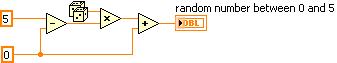
I'm trying to generate analog signals to simulate the position of the valve. I also want to simulate the position of the valve 0 - 5V (analog signal). I've implemented the numeric position of the valve by using the toggle switches, but I want to implement analog signals.
You can help.
Thank you
You can just use a random number generator.
Since you have no generator hardware signals of NOR, I'm not sure why you are posting to this Board. Generic questions of LabVIEW. Post to this Board.
-
Analog LIFA read problem of results
Hello guys, I just started using labVIEW for 2 months and I'm really new to this software.
In fact, my question is what kind of output will get for analog arduino read? (element-single number, or table-columns of data).
For my case, I use LIFA (LabVIEW interface for arduino) and an IMU is connected to my arduino. The IMU has 3 axes (X, Y, Z)
Is it possible to analog playback for tables with multiple columns or its always 1 single digit?
I can hardly get information on this and thank you in advance if you can help me
The LIFA Toolbox has a low level of pin reading and reading Port. The port of reading read more or less at the same time all 6 inputs analog. I have to open the source for whether or not it's really both. This value is returned as an array with 6 elements.
Maybe you are looking for
-
How to unlock a site Web to use a plug-in when activating the plugin defined as 'Ask to activate?
Hi all In the desperate not to use Flash more attempts, I put the activation setting to 'ask to activate '. Then I went on a website (which uses the Flash) and Firefox prompted me if yes or not I allow this Web site says to use the Flash. I didn't al
-
I reinstalled firefox pinterest bookmarklet no longer works, why?
I have a Mac with OS 10.5.8. I have Firefox 3.6.28. For reasons too long to quote I had to reinstall Firefox. I don't know what was the previous version. I'm more able to use the bookmarklet pinterest. It worked fine before the reinstall. The bookmar
-
Hi all I wrote an application that takes care of the interface user-swappable. This has been achieved by my user interface via Server opening VI and passing a cluster of references to the application main VI control UI and their inclusion in the dyna
-
How to separate the IVI of the particular instrument channels
-
My antivirus software keeps advising me that igrs.exe wants to have access to the internet. I did a search and found several sites that say it is a virus. Don't want to remove until I know. We know what it is?