generation of two complementary pwm signals using myrio
Hello, im working on a project and I need to generate two complementary pwm signals (when we go to 1, the other goes to 0) using myrio.
the problem with the blocks of myrio pwm is that when you set the market factor, the signal always starts with its high value. Can someone help me please?
Hello
You can create a Boolean square signal with chosen service and frequency cycle, create its opposite with makes NO sense and then send both signals via Digital Out vi (myRIO/Default/Digital Out) to two different outputs.
Best regards
Tags: NI Products
Similar Questions
-
Problem in reading the PWM signals in myRIO 1900
Hi guys,.
I work with myRIO to generate PWM pulses.
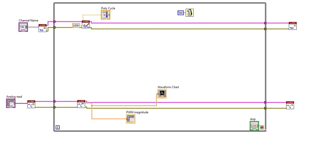
Here is the block diagram of my circuit.
I connected external to the analog input pin PWM pin. So I can watch the PWM pulse in the waveform table.
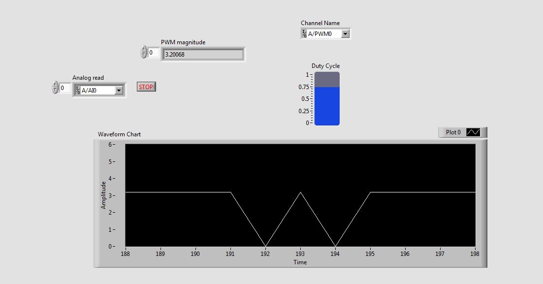
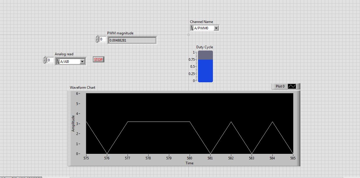
But the waveform is not clear. This is as shown in the screenshot.
See that the waveform is not correct. When I'm watching the same PWM pulses in the CRO (cathode ray Oscilloscope, oscilloscope real in the real world), I get exactly the waveform. that is, the PWM pulses are generated correctly. But the analog read is unable to read the PWM pulses.
I faced the same problem with the pin of analog reading earlier when I read the input voltage. Is not give continuous reading of the voltage input.
Please guide me how to read these impulses via analog read.
Please tell me at what frequency range, I can use this myRIO to generate impulses?
I am able to use 40 kHz?
Hi rcs.
The desired pulse frequency is 10 KHz. My sampling rate must therefore 100 kHz, which is not possible in data acquisition mode. There is another problem with the myRIO. Only AI0, BI0 and CI0 has n-sample mode. The analog input pins is still have no n-sample mode. But in my project, I need 4 pins of I in n-sample mode, which is not possible. In addition, the sampling rate should also be favourable, which does not happen in my case. We can say that this is a disadvantage of myRIO with data acquisition mode.
The only alternative to solve this problem is to use FPGA in myRIO.
He can taste a 25nS rate.
But little complexity is there -
Generation of two channel analog output using NI USB-6221
-
How can I use the USRP to record a signal using its two RX ports simultaneously?
Hello.
I am trying to record a signal using two antenna cone. The reason that I need two antenna to cover the bandwidth (DC - 6 GHz). a single antenna covers DC - 300 MHz and the other covers 300 MHz to 6 GHz. so I need to use two RX port of USRP at the same time to record the signal. I have two questions:
1. is this all USRP market capable of covering this frequency range?
2. is it possible to use the two RX port at the same time to the signals of the records I described? If this is not the case, how can do?
P.S. I have two NI2920 USRPs and two USRPs N210 in my lab.
Thanks in advance for your time.
Sam.
Hi Sam,
To answer your first question, the USRPs you can reach the bandwidth you want. There is not a USRP, to my knowledge, that can reach this range in a single device.
Also note that you can only use RX convened for two different ports at the same time using LabVIEW and the pilot of the USRP. If you want to use the two lines of RX, you will need to run a session with a single line, close the session and then start a different session for your second RX line.
-
Voltage offset problems with the NO-9401 for PWM signal output
I try to create a 20 kHz PWM signal to drive a motor control circuit uses the NI 9401 module in the chassis OR cRIO-9073. Generating the PWM signal works. For some reason, changes in shift of power as the market factor is increased. It is less effective for the engine, as you can imagine.
The code I am using is the finder of the example, for the generation of PWM on an FPGA and is attached.
I thought that it worked before but may have used the the NOR-9505 rather PWM output to test my circuit. It would be unreasonable for me to do this as a permanent solution.
The problem can be summed up as: with an increase in the liability of the cycle the voltage line (offset) movement of the output signal in the negative (according to ADGE) Basic or down. The Vpp signal is correct and does not change. Against ticks from 0 to the maximum of 2000 ticks (duty cycle IN), the offset voltage shift is such that 100% the level of full voltage is 0V.
Any ideas as to why this offset voltage shift that happens?
Do not be dismayed, I worked on the problem. There was a connection problem - I thought I was logged in as reference Earth, but it has not been properly clipped.
-
Problem when the PWM signal combinning and analog signal TOGETHER!
Hello everyone,
first I DAQmx 6212, and I need to run the water pump small (9V - 16V) that should be driven by a PWM signal; I also have a motor (5V - 13V) for a water supply which must be controlled by an analog signal and it has built in a force feedback potentiometer, I logged onto this potentiometer correction + 5V the DAQmx and used the output voltage of the third extremety as a value to diagnose to know the position of the engine.
My VI shows:
1 is a normal meter production to create my PWMout signal.
2 is an analog input, I use it as a PWMin to the LabVIEW to diagnose what is happenning in my pump water through the cycle and frequency.
3 is an entry of the third extremety of the analog potentiometer.
4 is an analog output that I used as power supply of the motor valve and I used an AC/DC amplifier for aplify signal the DAQmx and the motor road, between the two (3. 4.) I made a comeback with a few calculations, I had a P-controller to know the real position of the engine valve.
My problem:
When setting to 1. and 2. in the same VI only, I get an own PWM output with no problem.
also with 3. and 4. in the same VI only i can control the motor valve without any problem.
but when I put all these 4 set found in the attached VI, I have a problem as the engine valve turn continuously without stopping even if I change the position of the valve between 0 and 100%, I should mention that I see a PWM normal outside a signal on my oscilloscope, another thing to delete one of (1 or 2) and run the engine valve VI works fine without any problems.
so this my problem, if you can think of any solution please let me know.
Thanks in advance for your help.
Kind regards
Caliente
Here's your VI, slightly modified so the two analog inputs belong to the same task. This if only for purposes of illustration, I him have not tested. You will still need to do some debugging.
While changing your VI, I noticed another potential problem with your original configuration. You have configured the two tasks of AI for the same frequency, but read you 10000 samples of one of them and only 100 samples from the other (and throw it most of it). Data acquisition data are buffered, and if you read as fast as you acquire, the buffer fills eventually. If you read 10,000 samples of a channel, and the other channel acquires at the same rate, then when you read from the second channel you will get old stale data or an error full buffer.
-
Hi guys!
I'm working on a project where I want to control a motor dc with VirtualBench and LabView.
I have the engine connected to a H-Bridge motor, so I need to send 3 digital signals from the DIO VirtualBench to H-bridge.
With respect to management, I figured out, but now I need help to get a PWM signal to one of the DIO pins.
I can generate a PWM of the FGEN but do not know how to export to a DIO PIN.
I can also generate a PWM with the Express-> entry-> function Generate signal in Labview. But I get an error when you try to write this signal to pin.
Or is there a way smarter or easier?
Help, please!
/ Christian
The digital i/o pins are supported as the SPI, I2C, static DIO (timed by the software) and exports of MSO Trigger or FGEN signals start. There isn't any feature PWM/meter.
It is not a way to generate a PWM signal real on the DIO pins, nor can you give a digital waveform to dig write. From the FGEN might be your best option here.
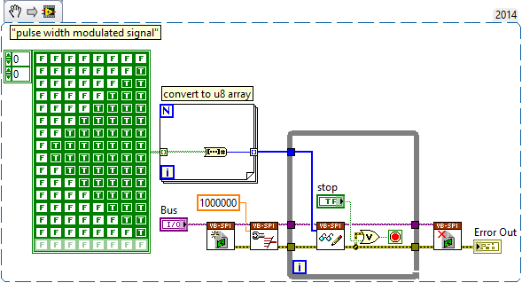
Another possibility might be to use (ab) the functionality of mastering of SPI. The following VI generates a modulated signal of pulse on dig/1 (MOSI) width. It will also generate signals on dig/0 (CLK) and dig/3 (CS), which may not be desirable, and you will have "gaps" between each call to read write of SPI.
-
How can I measure the output of a sensor pwm ultrasound using the module or 9403
How can I measure the output of a sensor pwm ultrasound using the module or 9403
Khalil,
When you say 'measure' the PWM signal, exactly what to tell you?
You're looking to measure the frequency or cycle of the signal function? You count the edges of the PWM output increase? Looking to control the waveform?
With reconfigurable FPGA hardware, it is up to the user to define the function of the physical i/o on the FPGA chip. By connecting the signals as Adam suggests your digital pulse will be brought to the cRIO. In your FPGA program, you define the function. You can set a base counter or transfer digital data from single point to welcome you cRIO for floating-point more complex treatment. Example FPGA programs are located in the http://www.ni.com/IPnet.
Hope this helps, please post any additional questions.
-
bad examples in two documents of signal edge separation
In the folder 'Two signals separation edge' examples are not two examples of signal.
They are two edge separation measurements made on a single signal.
I'm for any edges ofrising of separation between two signals Encoder on pairs of consecutive 1024 pulses. I couldn't find an example for this.
Is there something I could try?
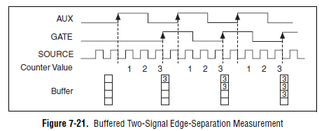
Looks like you want something like this (Image of the M series user manual):
If you want to measure a finite number of impulses, you must use the 'soul two edge separation - Finite.vi buffered"is shown in the screenshot in your example finder. You must connect your two signals to the entries ' to the ' and 'GATE' of your meter. On many boards (for example, plugin M series), the default lines used are:
CTR 0:
To THE: PFI 10 (PIN 45)
PORTAL: PFI 9 (PIN 3)
CTR 1:
TO THE: PFI 11 (PIN 46)
PORTAL: PFI 4 (Paperback 41)
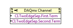
If you don't want to use the default values, you can edit the lines used with a channel property node DAQmx PFI:
The examples you linked measurement of separation edge on two different signals in the manner illustrated in the diagram above.
Best regards
-
How to generate two different analog signals in two different screws
I use a card PCIe-6321 and a block of connection SCB-68. As it has two analog outputs, I use one of these outputs in a Vi to generate a square wave, and the other in an another VI to generate a sinusoidal output waveform. Each VI perfectly work separately, but if I run one then the other, the other sends no signal. Because I don't want to merge the two screws (it is more convenient to use them separately), how can I find out so that they work together (sometimes).
Of course, independent maps with timing motors, controlled by the works of independent screws.
Christian
-
Generate PWM signals with 1.5 ms pulse width
Hi all
I'm working on a project where I need to generate a PWM with a pulse between 1.3 and 1.7 width ms to order a servo rotation continues. LabView is in communication with an arduino Uno microcontroller by LINX. My original plan was to use the milliseconds of wait function in LabVIew to do this. I put the PIN PWM high, wait 1.3 or 1.4 ms then set the low axis for 20 less ms pulsewidth. before repeating. This is how I have gnereate one using the Arduino IDE pulse width, so I thought I'd be able to do something similar here. However, as I'm sure is already obvious to anyone who reads this, the milliseconds waiting finction in LabView only accepts the whole entries. Arduino IDE is similar, but there is a delayMicrosecond function that can be used, so if I want 1.4 ms I use 1400 US snf then convert it in ms for the 20 least part. How can I do something similar in LabView? Also. When I run the program as what with a 1 ms pulsewidth I have a strange behavior. It in fact generates a PWM signal, somewhere between 0.75 and 1.25 ms and with a period between 50 and 54 ms, it turns into a model each about half a second. I'm using LabView 2014. Any ideas?
Chris
You can't get that kind of resolution with Windows and any delay you specify will have considerable jitter due to Windows. If you can pass values with Linx and allows the arduino to control them, stick with that.
-
Why are there at - it such a delay, write and read a PWM signal to digital input?
Hello! I am trying to read and take action on a PWM signal. The equiptment I'll have access to: 9201, 9425 and cDAQ-9172 chassis of NOR.
That's kind of what I'm experimenting with now (I have tested with a device USB 6211). Someone at - it a better idea how to do that?
The problems that I encounter:
(1) it seems there be then buffering of questions?
(2) it takes too long.
My vi is attached.
Thanks in advance for any help you can give.
Also, in my final application, I will not have to create the PWM signal - this is just to test the acquisition currently.
Try to use functions DAQmx directly rather than the DAQ Assistant. They are a little more work to learn but are more effective. Your 6211 can generate a PWM signal in hardware, so use it (see examples of LabVIEW). Finally, of course there will be some delay in your code. You read to 1.5 k samples to 1 k/second, so each loop cycle will be 1.5 s.
EDIT: also, why you write 1 k samples and then read 1.5 k, both 1 k per second? This means that your output will not generate any signal for long periods of time...
-
How can I transfer photos from my iPod touch 6th generation for my macbook pro WITHOUT using iCloud, please? It's simple with another camera but not the case, it seems, for the iPod Touch from Apple.
Use import option from your Mac:
Import photos and videos from your iPhone, iPad or iPod touch - Apple Support
-
Reading of analog signal using DAQPad-6016
I'm reading an analog signal using DAQPad-6016. An entry is on the ground, the other is Vdc. I can't operate at MAX and I'm confused becaue MAX alone gives me an option for differential reading, but the list of pins give enough information on how to connect in a different way. Is there a reference as well?
Hello, Bernadette.
This link should have what it takes to equip themselves properly: http://www.ni.com/gettingstarted/setuphardware/dataacquisition/analogvoltage.htm
After that you have put work in place, specifically see step 11 for check the connections of the device.
I hope this helps!
-
I have 3 computers running Windows 7 Professional, one of them has a four installed tuner DVB - s2 card. I want to configure it as a server and the other two as clients, each using two of the tuners of the card. I understand the media library is able to use the basic network TV tuning cards, so there must be some way for me to configure the server to send the information over the network.
Any ideas?
On Fri, September 19, 2014 12:28:56 + 0000, SamJ008 wrote:> I have 3 computers running Windows 7 Professional, one of them has a four installed tuner DVB - s2 card. I want to configure it as a server and the other two as clients, each using two of the tuners of the card. I understand the media library is able to use the basic network TV tuning cards, so there must be some way for me to configure the server to send the information over the network.>>>>>>> Any ideasStart reading hereYou will not be able to use your existing tuners like tuner network. Microsoft hasarrested development of Media Center, so don't expect any new hardware/software toappear.__________________________________________________________________________________________________BarbMVP Windows Entertainment and connected homeMy Blog - http://digitalmediaphile.com/Please mark as answer if that answers your question
Maybe you are looking for
-
After you download the new operating system i.e. sierra, my iMac has slowed down considerably. It takes a lot of time to open applications.
-
Impossible to install applications - need permissions
Your question has been answered almost four years ago. Did you ever get an answer? I recently started having the same problem. http://answers.Microsoft.com/en-us/Windows/Forum/windows_xp-windows_install/i-am-the-administratorowner-on-my-PC-i-am-una
-
Cleaning or replacement keyboard om M5-581TG
Is there a way to clean or replace the keyboard on the M5-581TG model? Some of the keys on the integrated keyboard has stopped working after an accident involving liquids. Is it possible to remove the keys without damaging them? Or is it possible to
-
My computer wants to Miss AppEx accelerator network FLM. How can I get it back?
I can have uninstalled this hidden network card and want to reinstall.
-
Push message to external users
Hi all We have a Blackberry Enterprise Server. Is it possible to send a push (pap) message to external users (not the registration in our BES)? Thank you