Problem in reading the PWM signals in myRIO 1900
Hi guys,.
I work with myRIO to generate PWM pulses.
Here is the block diagram of my circuit.
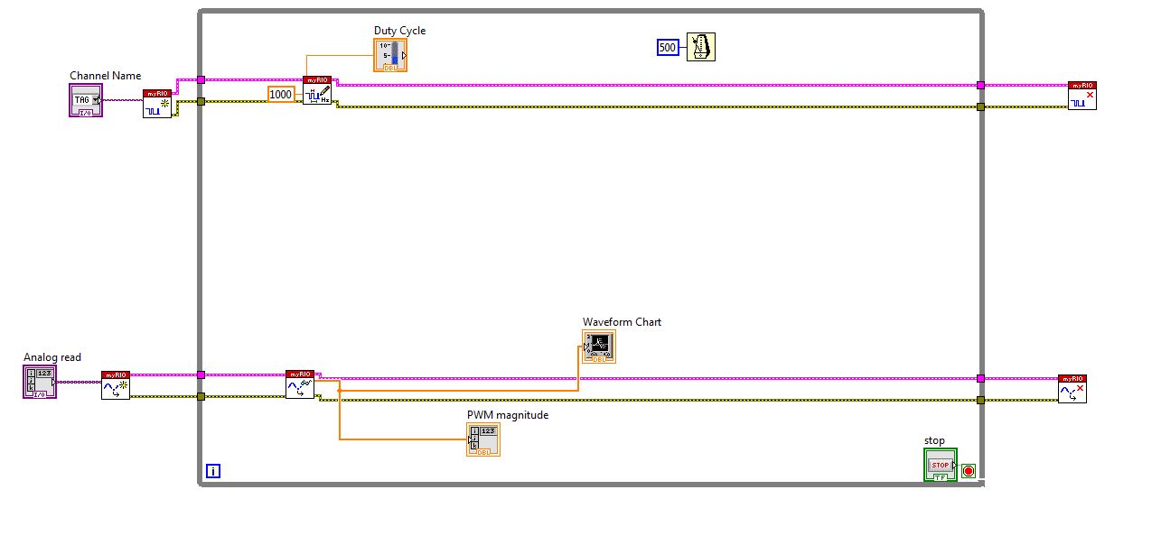
I connected external to the analog input pin PWM pin. So I can watch the PWM pulse in the waveform table.
But the waveform is not clear. This is as shown in the screenshot.
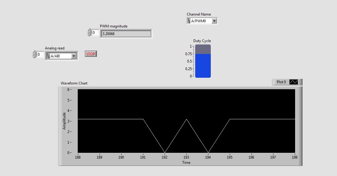
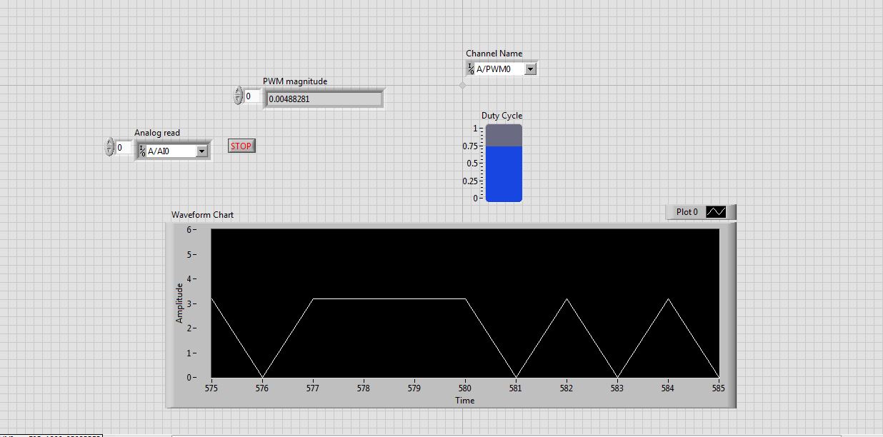
See that the waveform is not correct. When I'm watching the same PWM pulses in the CRO (cathode ray Oscilloscope, oscilloscope real in the real world), I get exactly the waveform. that is, the PWM pulses are generated correctly. But the analog read is unable to read the PWM pulses.
I faced the same problem with the pin of analog reading earlier when I read the input voltage. Is not give continuous reading of the voltage input.
Please guide me how to read these impulses via analog read.
Please tell me at what frequency range, I can use this myRIO to generate impulses?
I am able to use 40 kHz?
Hi rcs.
The desired pulse frequency is 10 KHz. My sampling rate must therefore 100 kHz, which is not possible in data acquisition mode. There is another problem with the myRIO. Only AI0, BI0 and CI0 has n-sample mode. The analog input pins is still have no n-sample mode. But in my project, I need 4 pins of I in n-sample mode, which is not possible. In addition, the sampling rate should also be favourable, which does not happen in my case. We can say that this is a disadvantage of myRIO with data acquisition mode.
The only alternative to solve this problem is to use FPGA in myRIO.
He can taste a 25nS rate.
But little complexity is there
Tags: NI Products
Similar Questions
-
Why are there at - it such a delay, write and read a PWM signal to digital input?
Hello! I am trying to read and take action on a PWM signal. The equiptment I'll have access to: 9201, 9425 and cDAQ-9172 chassis of NOR.
That's kind of what I'm experimenting with now (I have tested with a device USB 6211). Someone at - it a better idea how to do that?
The problems that I encounter:
(1) it seems there be then buffering of questions?
(2) it takes too long.
My vi is attached.
Thanks in advance for any help you can give.
Also, in my final application, I will not have to create the PWM signal - this is just to test the acquisition currently.
Try to use functions DAQmx directly rather than the DAQ Assistant. They are a little more work to learn but are more effective. Your 6211 can generate a PWM signal in hardware, so use it (see examples of LabVIEW). Finally, of course there will be some delay in your code. You read to 1.5 k samples to 1 k/second, so each loop cycle will be 1.5 s.
EDIT: also, why you write 1 k samples and then read 1.5 k, both 1 k per second? This means that your output will not generate any signal for long periods of time...
-
read the analog signal 0-10 volts of NI6123
I'm reading the analog signal of NI 6123. The range of the analog signal is 0 to 10 volts. This works well when the signal voltage is 0 to 5v (0 ~ 32767). But when the signal is 5 to 10 volts, the value read is always 32767. I also tried the different reading function: DAQmxReadBinaryI32, DAQmxReadBinaryU16, DAQmxReadBinaryU32. The value is identical to DAQmxReadBinaryI16. My OS is windows vista. Here's the part of my codes.
**************************************************************************************************************************************************************************
Create analog data tasks.
DAQmxErrChk (DAQmxCreateTask("",&datHandler));
DAQmxErrChk (DAQmxCreateAIVoltageChan(datHandler,"Dev1/ai0:7","",DAQmx_Val_Cfg_Default,-10,10,DAQmx_Val_Volts,NULL));)
DAQmxErrChk (DAQmxCfgSampClkTiming(datHandler,"",RATE,DAQmx_Val_Rising,DAQmx_Val_ContSamps,RATE*MAXLAS));
DAQmxErrChk (GetTerminalNameWithDevPrefix(datHandler,"ai/SampleClock",trigName));
Create counter tasks.
DAQmxErrChk (DAQmxCreateTask("",&ctrHandler));
DAQmxErrChk (DAQmxCreateCICountEdgesChan(ctrHandler,"Dev1/ctr1","",DAQmx_Val_Rising,0,DAQmx_Val_ExtControlled));
DAQmxErrChk (DAQmxCfgSampClkTiming(ctrHandler,trigName,RATE,DAQmx_Val_Rising,DAQmx_Val_ContSamps,RATE));
DAQmxErrChk (DAQmxRegisterEveryNSamplesEvent (datHandler, DAQmx_Val_Acquired_Into_Buffer, SPLEEN, 0, EveryNCallback, NULL));
DAQmxErrChk (DAQmxRegisterDoneEvent(datHandler,0,DoneCallback,));
Start the task.
DAQmxErrChk (DAQmxStartTask (ctrHandler));
DAQmxErrChk (DAQmxStartTask (datHandler));
In the call back function:
DAQmxErrChk (DAQmxReadBinaryI16 (datHandler, SPLEEN, 3.0, DAQmx_Val_GroupByChannel, data.laser, MISS * MAXLAS, & (data.dataRead), NULL));
DAQmxErrChk (DAQmxReadCounterU32 (ctrHandler, SPLEEN, 3.0, data.counter, SPLEEN, & (data.ctrRead), NULL));
write data to the file.
data.cfile.Write (data.counter, sizeof (int32) * RATE);
data.cfile.Write (data.laser, sizeof (int16) * RATE * MAXLAS);
**************************************************************************************************************************************************************************
Thanks in advance
To make sure that your device is working properly, I recommend first to test the entry in measurement and Automation Explorer (MAX) analog. You can test your device by right clicking on it in the configuration tree and selecting test panels. See if you acquired signal 0 - 10V as you expect. The next step would be to try one of the sample programs that perform a task of analog input. These examples can be found in the start menu > programs > National Instruments > NOR-DAQ > text based code supported. Try an example that does an analog input continues and double bed (instead of binary data not adjusted).
Your program looks good at first so I found nothing that stood out. However, one thing to check is if your function generator (or signal source) expects a 50 ohm or high impedance. This could cause reflections of the signal and cause the device to possibly read a voltage of half of the desired value.
-
Hello
I'm working on the UI for a 2 month Word Press theme, and it has a ton of layers with file size of 900 MB.
When designing, I get a message that says:
"here was a problem to read the data in the layer. read the composite data instead? »
Please solve this problem because I am so tired of working on this that I don't want this effort in vain.
and sorry if my English is bad.

Hi AymanAlrifai,
Would you be able to share the file problem with me zipped upward? petgreen [at] adobe [dot] com
I'll see if I have the same problem and check with the team to investigate the issue here and see if we can resolve it for you.
Kind regards
Pete
-
Problem when the PWM signal combinning and analog signal TOGETHER!
Hello everyone,
first I DAQmx 6212, and I need to run the water pump small (9V - 16V) that should be driven by a PWM signal; I also have a motor (5V - 13V) for a water supply which must be controlled by an analog signal and it has built in a force feedback potentiometer, I logged onto this potentiometer correction + 5V the DAQmx and used the output voltage of the third extremety as a value to diagnose to know the position of the engine.
My VI shows:
1 is a normal meter production to create my PWMout signal.
2 is an analog input, I use it as a PWMin to the LabVIEW to diagnose what is happenning in my pump water through the cycle and frequency.
3 is an entry of the third extremety of the analog potentiometer.
4 is an analog output that I used as power supply of the motor valve and I used an AC/DC amplifier for aplify signal the DAQmx and the motor road, between the two (3. 4.) I made a comeback with a few calculations, I had a P-controller to know the real position of the engine valve.
My problem:
When setting to 1. and 2. in the same VI only, I get an own PWM output with no problem.
also with 3. and 4. in the same VI only i can control the motor valve without any problem.
but when I put all these 4 set found in the attached VI, I have a problem as the engine valve turn continuously without stopping even if I change the position of the valve between 0 and 100%, I should mention that I see a PWM normal outside a signal on my oscilloscope, another thing to delete one of (1 or 2) and run the engine valve VI works fine without any problems.
so this my problem, if you can think of any solution please let me know.
Thanks in advance for your help.
Kind regards
Caliente
Here's your VI, slightly modified so the two analog inputs belong to the same task. This if only for purposes of illustration, I him have not tested. You will still need to do some debugging.
While changing your VI, I noticed another potential problem with your original configuration. You have configured the two tasks of AI for the same frequency, but read you 10000 samples of one of them and only 100 samples from the other (and throw it most of it). Data acquisition data are buffered, and if you read as fast as you acquire, the buffer fills eventually. If you read 10,000 samples of a channel, and the other channel acquires at the same rate, then when you read from the second channel you will get old stale data or an error full buffer.
-
generation of two complementary pwm signals using myrio
Hello, im working on a project and I need to generate two complementary pwm signals (when we go to 1, the other goes to 0) using myrio.
the problem with the blocks of myrio pwm is that when you set the market factor, the signal always starts with its high value. Can someone help me please?
Hello
You can create a Boolean square signal with chosen service and frequency cycle, create its opposite with makes NO sense and then send both signals via Digital Out vi (myRIO/Default/Digital Out) to two different outputs.
Best regards
-
Problem to read the details of the new widget news
I'm having a problem of reading new news of the widget. Maybe someone could help me.
When I click on the title of a news article, it opens the browser, seems to go to the site news.qwapi.com and returns an erros indicating that the site is currently unavailable. Things seemed to work fine until a few days ago and I did not recent changes that I'm aware of that could be the cause of this problem.
It happens not all the press articles, some successfully opened on Reuers, etc..
Did anyone else encounter this problem with their Cliq XT?
Concerning
I had the same problem this morning, just removed and added the widget to the home screen, and it worked fine afterwards.
-
Problem using: read the spreadsheet file
Hello
I have 2 problems with reading spreadsheet file:
(1) for the use of .txt file I can get the first column and not the other (even if I chose the correct output...)
(2) this does not at all when you use my .xls file
I must do something wrong but can't find what...
Has anyone an idea?
I have attached the .VI and my two files.
Thank you
User
A native Excel file is NOT a text file. It is a format of custom file created by Microsoft. This is why you must use ActiveX to interact with him.
The worksheet ' ' folder features found in the work of LabVIEW with text files (delimited by tabs, CSV, etc.). The text files are a format more generic that can be read by programs such as Notepad. Tried to use Notepad to open an .xls file? It does not work. Excel can open a text file, because it is a generic format.
So even if everyone automatically thinks "Excel" when they see the word "Spreadsheet", the two are not synonymous. In the case of LabVIEW, 'Spreadsheet' made reference to a delimited text file.
Who is?
-
Problems with reading the series bytes
Hello
I currently have a PIC18F microcontroller serial communication with LABview using the base read and write.vi series. The PEAK sends strings such as "V222! (V is the character of the header, and! being the end character). Then, I have a program to take each individual character read and concatenate them in a larger string for data extraction. The port has been configured to 38400 baud and be only a single byte of long.
The captain sends this one byte at the time and the problem here is that LABview seems to be only reading V most of the time, and occasinally has 2. Since it doesn't seem to be never read the end character, the sequence of extracting data from my code is never executed.
A few questions I have are:
The captain may send one byte at a time, but also all other devices communicate through a serial port. The definition of the serial port involves both a byte. Actually it's really a LITTLE at a time. But serial port parameters leads to the gathering of 7 or 8 bits to produce a byte. The PEAK sends a follow-up byte to another byte, etc. The time between shipments of the byte may be too small to read contiguously in your Labview program.
At very slow speeds, it could really work. At 300 baud (3mS / bit), there are 33 mS to send a byte (8-bit + stop bit, start bit). So if your loop runs fast enough, you get every byte one at a time. But there is the overhead of other code to store the bytes, etc..
38000 baud to only 0.2 mS to send a byte. LabVIEW is not fast enough to loop at this rate to capture all the bytes individually.
But why bother? Simply capture all the bytes and treat them as a complete message.
-
Problem in reading the value of field ITResourceLookup
Hi all
I HAV created as an object with a field of ITResourceLookup. Also I HAV created a task assignment to the choice the approver adapter dynamically a file. This adapter calls a java method to read the approver in the properties for the selected ITResource file.
I am facing problem in the adapter mapping variable operational assignment with ITResourceLookup field of the shape of the object. Sound does not come as a string or a long. Please suggest how to read the name of the resource.
INIYAYou can always pass the key of the instance and then use the api to get the value of the form data.
-Kevin
-
Problem in reading the file RAW, the ARW by Sony A7
I use LR 5.7 with Camera Raw 8.7 with my Macbook.
I don't know why it does not read the type ARW file created by Sony camera.
Help, please.
Correct, 5.7.1 is the latest version of the LR5. For the LR6, you have the choice of buying an upgrade for about $ 80 autonomous, perpetual License or you purchase a package.
You can also use the DNG Converter, free, convert to DNG and import them into your current LR5.
I suggest upgrading to LR 6 and don't miss out on what's new. Don't forget to update 6.1.1 and not the last 6.2 / 6.2.1.
-
Hey,.
Is it possible to read a signal HERE, with a range of 1 mV-150 mV, thanks to an acquisition of data USB-6210?
How do we?
Kind regards
Filip Van Boxstael
-200 mV to + 200mV is a range. The DAQ hardware will measure a voltage within this range. If you need to measure something outside this range, you must select the next higher range. Since you mention 150mV for you the maximum voltage, 200mV beach is perfect.
-
Problem in reading the spectrum
Hi all @SynergyMike,
I found the solution to the problem... The initialize Vi at the beginning that we must retain the value of fake reset so it remains empty and read only one value... Just try it...
Thank you so much everyone...
Patricia
-
problem in reading the http to RSS feed link
I am using Blackberry Widget plugin Eclipse.
I'm having the problem, when I read a rss file, there is a http link in the rss. I try to read it out and javascript : alert (out). But it is not a vacuum 'i' icon. I check the source rss and the link is already exist. I don't know why I can't print it or use it as link hyper after I have change the file config.xml with the addition.
And besides, my current Simulator is 9550 in the eclipse (which is the default). How can I change my 9800 6.0.0.337 Simulator? I download and install the Simulator. But I can't find any option in the properties of the eclipse.
OK I have a solution of quenching.
After I use AJAX to get the response code, I use javascript : () for all know to replace and replace them in
, then use jquery to find . The link see the and view as well. This means that the Simulator or jquery itself cannot find the .
-
First Elements 7: problems to read the mts video format
Hi all
I need a little help here:
I have currently two adobe first elements 7 and corel video studio 11 is installed on the same computer. I am able to import video from my canon HG10 (MTS) files no problem in both programs. Hwoever, I am experiencing extreme video and voice in adobe, but not in my corel offset. I prefer to do all my video editing in adobe. Am I missing something? using the preset wrong? Please help... can be specific to the present I have to use to play good mts video in adobe?
My current system:
processor Intel core 2 duo CPU
3.50 GB of ram
NVIDIA 9600GT
Thank you
Peter
The Canon HG10 is a more intensive camcorder AVCHD video format to change. Most of the people who are editing in Premiere Elements successfully use processors quad core with 4 GB of RAM. It's possible Corel operates somewhat more effectively and could possibly run on your system. (Make sure you that you make your video in first items, pressing ENTER to keep the red line along the top of the timeline from firing at the Green, before you judge playback of the video.)
However, ensure that when you edit in Premiere Elements that you are using a predefined project AVCHD and you are using the media Downloader (under organize, get the media, AVCHD camcorder) to download your video from the camcorder. Using a program to capture your video and the other for editing can often lead to problems you encounter.

Maybe you are looking for
-
How to remove the label addess when will links
Whenever my mouse is over a link, the address is on the label at the bottom of the pages. It's REALLY annoying because the design of the websites that I use the most put the STATUS of the services at the bottom. So anywhere is my makeup of mice the n
-
I have a HP Pavilion p6730f desktop computer. My browser upgraded to Internet Explorer 11, but only needs can be done until I installed Windows 7 SP1. Where can I download SP1?
-
Problem with the camera and WIFI/Bluetooth in G580
The Webcam is not detected by the system. Device Manager displays 'Lenovo Easy Camera' under features of imagery but Windows camera Application or third-party software like Skype detect. Installed the latest drivers etc but no avail. Similarly, it ha
-
How to remove virus folder searchplugins
How to remove virus folder searchplugins
-
you are using windows vista 32. A new problem. When I try to run multiple deletes all leaky windows open in a small window. I have to go back and narrow everysmall window until I can do multipe deletes. This does happen evry time, but most of the tim