Export to the DIO PWM signal
Hi guys!
I'm working on a project where I want to control a motor dc with VirtualBench and LabView.
I have the engine connected to a H-Bridge motor, so I need to send 3 digital signals from the DIO VirtualBench to H-bridge.
With respect to management, I figured out, but now I need help to get a PWM signal to one of the DIO pins.
I can generate a PWM of the FGEN but do not know how to export to a DIO PIN.
I can also generate a PWM with the Express-> entry-> function Generate signal in Labview. But I get an error when you try to write this signal to pin.
Or is there a way smarter or easier?
Help, please!
/ Christian
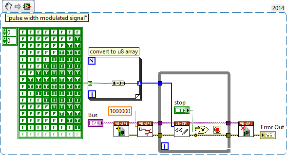
The digital i/o pins are supported as the SPI, I2C, static DIO (timed by the software) and exports of MSO Trigger or FGEN signals start. There isn't any feature PWM/meter.
It is not a way to generate a PWM signal real on the DIO pins, nor can you give a digital waveform to dig write. From the FGEN might be your best option here.
Another possibility might be to use (ab) the functionality of mastering of SPI. The following VI generates a modulated signal of pulse on dig/1 (MOSI) width. It will also generate signals on dig/0 (CLK) and dig/3 (CS), which may not be desirable, and you will have "gaps" between each call to read write of SPI.
Tags: NI Products
Similar Questions
-
Voltage offset problems with the NO-9401 for PWM signal output
I try to create a 20 kHz PWM signal to drive a motor control circuit uses the NI 9401 module in the chassis OR cRIO-9073. Generating the PWM signal works. For some reason, changes in shift of power as the market factor is increased. It is less effective for the engine, as you can imagine.
The code I am using is the finder of the example, for the generation of PWM on an FPGA and is attached.
I thought that it worked before but may have used the the NOR-9505 rather PWM output to test my circuit. It would be unreasonable for me to do this as a permanent solution.
The problem can be summed up as: with an increase in the liability of the cycle the voltage line (offset) movement of the output signal in the negative (according to ADGE) Basic or down. The Vpp signal is correct and does not change. Against ticks from 0 to the maximum of 2000 ticks (duty cycle IN), the offset voltage shift is such that 100% the level of full voltage is 0V.
Any ideas as to why this offset voltage shift that happens?
Do not be dismayed, I worked on the problem. There was a connection problem - I thought I was logged in as reference Earth, but it has not been properly clipped.
-
Problem when the PWM signal combinning and analog signal TOGETHER!
Hello everyone,
first I DAQmx 6212, and I need to run the water pump small (9V - 16V) that should be driven by a PWM signal; I also have a motor (5V - 13V) for a water supply which must be controlled by an analog signal and it has built in a force feedback potentiometer, I logged onto this potentiometer correction + 5V the DAQmx and used the output voltage of the third extremety as a value to diagnose to know the position of the engine.
My VI shows:
1 is a normal meter production to create my PWMout signal.
2 is an analog input, I use it as a PWMin to the LabVIEW to diagnose what is happenning in my pump water through the cycle and frequency.
3 is an entry of the third extremety of the analog potentiometer.
4 is an analog output that I used as power supply of the motor valve and I used an AC/DC amplifier for aplify signal the DAQmx and the motor road, between the two (3. 4.) I made a comeback with a few calculations, I had a P-controller to know the real position of the engine valve.
My problem:
When setting to 1. and 2. in the same VI only, I get an own PWM output with no problem.
also with 3. and 4. in the same VI only i can control the motor valve without any problem.
but when I put all these 4 set found in the attached VI, I have a problem as the engine valve turn continuously without stopping even if I change the position of the valve between 0 and 100%, I should mention that I see a PWM normal outside a signal on my oscilloscope, another thing to delete one of (1 or 2) and run the engine valve VI works fine without any problems.
so this my problem, if you can think of any solution please let me know.
Thanks in advance for your help.
Kind regards
Caliente
Here's your VI, slightly modified so the two analog inputs belong to the same task. This if only for purposes of illustration, I him have not tested. You will still need to do some debugging.
While changing your VI, I noticed another potential problem with your original configuration. You have configured the two tasks of AI for the same frequency, but read you 10000 samples of one of them and only 100 samples from the other (and throw it most of it). Data acquisition data are buffered, and if you read as fast as you acquire, the buffer fills eventually. If you read 10,000 samples of a channel, and the other channel acquires at the same rate, then when you read from the second channel you will get old stale data or an error full buffer.
-
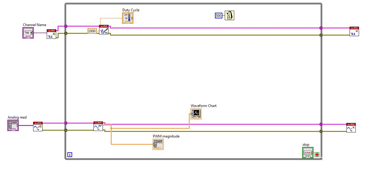
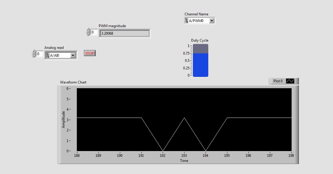
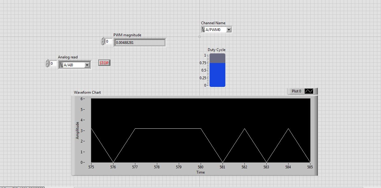
Problem in reading the PWM signals in myRIO 1900
Hi guys,.
I work with myRIO to generate PWM pulses.
Here is the block diagram of my circuit.
I connected external to the analog input pin PWM pin. So I can watch the PWM pulse in the waveform table.
But the waveform is not clear. This is as shown in the screenshot.
See that the waveform is not correct. When I'm watching the same PWM pulses in the CRO (cathode ray Oscilloscope, oscilloscope real in the real world), I get exactly the waveform. that is, the PWM pulses are generated correctly. But the analog read is unable to read the PWM pulses.
I faced the same problem with the pin of analog reading earlier when I read the input voltage. Is not give continuous reading of the voltage input.
Please guide me how to read these impulses via analog read.
Please tell me at what frequency range, I can use this myRIO to generate impulses?
I am able to use 40 kHz?
Hi rcs.
The desired pulse frequency is 10 KHz. My sampling rate must therefore 100 kHz, which is not possible in data acquisition mode. There is another problem with the myRIO. Only AI0, BI0 and CI0 has n-sample mode. The analog input pins is still have no n-sample mode. But in my project, I need 4 pins of I in n-sample mode, which is not possible. In addition, the sampling rate should also be favourable, which does not happen in my case. We can say that this is a disadvantage of myRIO with data acquisition mode.
The only alternative to solve this problem is to use FPGA in myRIO.
He can taste a 25nS rate.
But little complexity is there -
generation of two complementary pwm signals using myrio
Hello, im working on a project and I need to generate two complementary pwm signals (when we go to 1, the other goes to 0) using myrio.
the problem with the blocks of myrio pwm is that when you set the market factor, the signal always starts with its high value. Can someone help me please?
Hello
You can create a Boolean square signal with chosen service and frequency cycle, create its opposite with makes NO sense and then send both signals via Digital Out vi (myRIO/Default/Digital Out) to two different outputs.
Best regards
-
Why do I get error "20019 ADC conversion failed" with my pci-6143, when I try to use the DIO lines?
I am tyring to use one of the digital input lines on my PIC-6143 to go to the connection "enable" on the "write to file measure" vi. I have two cards PCI-6143 acquiring analog signals of 8 channels per step, plus I have a digital DAQ assistant to the sample line of DIO 2 on one of the cards. Normally I can start and stop recording using a signal of 5V to the DIO port several times until I get the error.
Strangely, when I use a simple Boolean "Record" button at the port of the 'writing on a file as' enable vi, I never get this ADC error no matter how many times I press the button.
I am including a screenshot of the error.
Thank you
Chris
Please ignore this message. The whole issue has been resolved by copying and pasting the VI in a new file in VI. The new file ran perfectly. Must have been a compilation of LabView or something error.
-
How do I get the analog input signal and send it to output analog (real time)
Hello world
I do a simple task in Visual C++ and I use PCI-6221(37 pin).
Basically, I want to send the same signal of "analog input" to the "analog output".
at the same time (or almost), to make real-time application.
Can someone provide me with sample program please.
I would be grateful if you could provide me with the great tutorial that explains
step by step everything about NOR-DAQmx for C/C++ programming.
Best regards
Khassan
This is my code in C++, you can optimize it if that seems too messy. This code reads the analog input signals and exports it through the analog outputs.
To make this code additional work of the directories include and library directories must be added to OR.
I hope it helps someone.
#include
#include
#include "NIDAQmx.h".
#include#define DAQmxErrChk (functionCall) {if (DAQmxFailed (error = (functionCall))) {goto error ;}}
int main (int argc, char * argv [])
{
Int32 error = 0;
TaskHandle taskHandleRead = 0, taskHandleWrite = 0;
Read Int32 = 0;
float64 context [1000];
char errBuffRead [2048] = {'\0'};
char errBuffWrite [2048] = {'\0'};
bool32 done = 0;
Int32 wrote;DAQmxErrChk (DAQmxCreateTask("",&taskHandleRead));
DAQmxErrChk (DAQmxCreateAIVoltageChan(taskHandleRead,"Dev1/ai0","",DAQmx_Val_Cfg_Default,-10.0,10.0,DAQmx_Val_Volts,NULL));
DAQmxErrChk (DAQmxCfgSampClkTiming(taskHandleRead,"",100.0,DAQmx_Val_Rising,DAQmx_Val_ContSamps,0));
DAQmxErrChk (DAQmxCreateTask("",&taskHandleWrite));
DAQmxErrChk (DAQmxCreateAOVoltageChan(taskHandleWrite,"Dev1/ao0","",-10.0,10.0,DAQmx_Val_Volts,NULL));
DAQmxErrChk (DAQmxCfgSampClkTiming(taskHandleWrite,"ai/SampleClock",100.0,DAQmx_Val_Rising,DAQmx_Val_ContSamps,1000));DAQmxErrChk (DAQmxStartTask (taskHandleRead));
DAQmxErrChk (DAQmxStartTask (taskHandleWrite));While (! fact &! _kbhit())
{
DAQmxErrChk (DAQmxReadAnalogF64(taskHandleRead,1,10,DAQmx_Val_GroupByScanNumber,dataRead,1000,&read,));
DAQmxErrChk (DAQmxWriteAnalogF64(taskHandleWrite,read,0,10.0,DAQmx_Val_GroupByChannel,dataRead,&written,));
}
_getch();Error:
If (DAQmxFailed (error)){
DAQmxGetExtendedErrorInfo (errBuffRead, 2048);
DAQmxGetExtendedErrorInfo (errBuffWrite, 2048);
}
If (taskHandleRead! = 0){
DAQmxStopTask (taskHandleRead);
DAQmxClearTask (taskHandleRead);
}
If (taskHandleWrite! = 0){
DAQmxStopTask (taskHandleWrite);
DAQmxClearTask (taskHandleWrite);
}
If {(DAQmxFailed (error))
printf ("error DAQmx: %s\n",errBuffRead); ")
printf ("error DAQmx: %s\n",errBuffWrite); ")
}
printf ("end of the program, press the Enter key to quit\n");
GetChar ();
return 0;
} -
Generate PWM signals with 1.5 ms pulse width
Hi all
I'm working on a project where I need to generate a PWM with a pulse between 1.3 and 1.7 width ms to order a servo rotation continues. LabView is in communication with an arduino Uno microcontroller by LINX. My original plan was to use the milliseconds of wait function in LabVIew to do this. I put the PIN PWM high, wait 1.3 or 1.4 ms then set the low axis for 20 less ms pulsewidth. before repeating. This is how I have gnereate one using the Arduino IDE pulse width, so I thought I'd be able to do something similar here. However, as I'm sure is already obvious to anyone who reads this, the milliseconds waiting finction in LabView only accepts the whole entries. Arduino IDE is similar, but there is a delayMicrosecond function that can be used, so if I want 1.4 ms I use 1400 US snf then convert it in ms for the 20 least part. How can I do something similar in LabView? Also. When I run the program as what with a 1 ms pulsewidth I have a strange behavior. It in fact generates a PWM signal, somewhere between 0.75 and 1.25 ms and with a period between 50 and 54 ms, it turns into a model each about half a second. I'm using LabView 2014. Any ideas?
Chris
You can't get that kind of resolution with Windows and any delay you specify will have considerable jitter due to Windows. If you can pass values with Linx and allows the arduino to control them, stick with that.
-
Why are there at - it such a delay, write and read a PWM signal to digital input?
Hello! I am trying to read and take action on a PWM signal. The equiptment I'll have access to: 9201, 9425 and cDAQ-9172 chassis of NOR.
That's kind of what I'm experimenting with now (I have tested with a device USB 6211). Someone at - it a better idea how to do that?
The problems that I encounter:
(1) it seems there be then buffering of questions?
(2) it takes too long.
My vi is attached.
Thanks in advance for any help you can give.
Also, in my final application, I will not have to create the PWM signal - this is just to test the acquisition currently.
Try to use functions DAQmx directly rather than the DAQ Assistant. They are a little more work to learn but are more effective. Your 6211 can generate a PWM signal in hardware, so use it (see examples of LabVIEW). Finally, of course there will be some delay in your code. You read to 1.5 k samples to 1 k/second, so each loop cycle will be 1.5 s.
EDIT: also, why you write 1 k samples and then read 1.5 k, both 1 k per second? This means that your output will not generate any signal for long periods of time...
-
I have a problem with that; It only gives me an option to export AIF and export all the files (including hidden tracks and muted)? any ideas on how to do it?
Thank you
OK, sorry, I think I understood the part 1 (amended the export bit rate). help with the export files?
-
How to export all the photos of Photos with the folder structure
Topic says it all...
I found tons of posts on how to export pictures from Photos, but clearly an important feature is missing. How to export one or more folders, subfolders, and albums to the breast?
I need on a regular basis (read: scripted) to export all my photos for use on another platform. But I need to keep my organized all files as they are in the pictures.
Anyone know of a script that can do this? Opening could [R.I.P].
Thanks 1million in adv.
Björn
Photos can export using the subfolder structure to give you the files corresponding to moments
a user has provided a script for this for albums - Albums export records - Script of Jacques Rioux
and old toad has planned that the script compiled as an app - http://www.oldtoadstutorials.net/No.P01.html
LN
-
Satellite A210-129: can I send the full HD signal on TV?
Hello.
I would like to ask if there is possibility to send videos in full hd laptop (it has only the D - Sub port). Thank you for your attention.
Can you please tell me how to send the full HD signal from your laptop without HD-DVD player and HDMI output? I think that it cannot work.
As far as I know that something like this is possible only on Qosmio G30 with HD-DVD and new Qosmio G40 player. The two laptops have the HD - DVD and HDMI output.
-
Update generation of over-the-air analog signals
Is there a way I can change this VI to allow real-time changes in the frequency, phase, amplitude and type of waveform to the continuous output through an acquisition of data NI 9263? For the moment, changes to these variables only happen in the output signal if the program has these variables set correctly when running.
The solution to this problem:
I found this VI, and this allows me to have the hardware buffer to be continually updated with new information of signal. The 2010 version, it works very well for me in the transmission of signals in direct update via my NI 9263 measurement system.
-
The document (msword) exported using the microsoft report viewer in VS2010 file corrupt after
Hello
After the export of the data of reportviewer in MS Word, the file is not opening. Finally, a mistake to corrupt the file. However, the export works very well with excel and pdf. The problem comes when the report contains several controls (around 100 (text boxes, rectange, table etc.). I tried to open the word file in MS Word 2003 and 2007, but not to open the file.
If the report viewer have less control then it is exported and open the file in word without any error. The word file open perfectly in MS-word 2007 but in Word 2003, the gridliness appear.
It is urgent. If someone has the solution so please let me know.
Thank you
S
HI San,
Your question of Windows is more complex than what is generally answered in the Microsoft Answers forums. It is better suited for the IT audience Pro on MSDN. Please post your question in the forum Visual Studio Developer Center.
http://social.msdn.Microsoft.com/forums/en-us/vsreportcontrols/threads
-
Black screen and mode standby with the message "no signal".
Correctly, it's... kind of weird, I use my computer and the monitor for a year or 2 now and don't never had real problems. The thing is that when I got home last night I found my black screen and standby mode (as if the computer was turned off (which it wasn't)). I thought that the reset will solve the problem, and so I did and didn't get the message "no signal". All tried, reconnecting cables, reset several times I could count... nothing helped for awhile.
At any given time during one of my restarts it reworked all of a sudden no aparent reason. So going on my daily buissiness I want to get back in the saddle, when I accidentally hit the side of my computer with a book and the screen went to 'no signal' again. Just tried again and even used my cell phone to check if the monitor was working,... now comes the weird part,... also on my laptor monitor is having problems with "no signal", but only when I do my main screen. It works as a secondary screen, but I can't get the context in which to work. (finding that I'm guessing that this problem is not related to my normal computer, but I'm not sure).
I am running vista and got a nvidia 8800GT graphics card. Also, I noticed something that is at any time using both the hdmi cable on the graphics card or using the socket with the internal chipset of my computer makes no difference. in both cases, I get "no signal" and the screen goes to sleep... Is there someone who can help me and tell me what probably is the problem here? I'm really looking forward to the answers, thank you very much for your time and effort.
Hi Ron Suykerbuyk,
If you are comfortable, then try to remove the CPU cover and check if the graphics card is well connected to the motherboard. Even if it is connected correctly, you can try to reconnect the graphics card and check.
Hope this information is useful.
Maybe you are looking for
-
Pavilion 17-g113dx: Can can't Do Factory Restore on the new Windows computer 10 17-g113dx
I'm doing f factory restore on my new computer with Windows 10 installed at the factory. When I go to Recovery Manager, choose the HP recovery environment, there is no option for the restoration of the factory. When I select the use a unit option, I
-
Drivers Windows 7 USB Controller
Recently, I went down my HP Pavilion TouchSmart 11-e015dx notebook from Windows 8 for Windows 7. Only Windows 8 drivers are listed on the support page, but they seemed all to install and works great. The only problem is that my right two USB 2.0 port
-
Accidentally, I changed my old ten years Apple ID. Did I lose all my iTunes purchases?
A week ago, I got an email from Apple saying that someone had attempted to buy something using my Apple ID. They suggested that I change my password, and I did. Somehow I ended up changing my Apple ID, I had at least 10 years. Now I fear that I will
-
Just bought a new computer with Windows 10. Can I transfer Acrobat 9 Pro from my old computer?
I just bought a new computer and want to load my Acrobat 9 Pro top. Is it possible to do?!@
-
We have replaced existing oraenv, coraenv db_home applying the patch 10.2.0.4 on 10.2.0.1
Hello everyone;I managed 10.2.0.4 binary installation is complete on 10.2.0.1. but we have made smallerror when running root.sh we smashed existing oraenv coraenv db_home (10.2.0.1)can I continue? or uninstall the patch?Thank you...