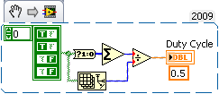
Get the duty cycle of DAQ to analog voltage input module
Hello.
I'm new to labview. I have an analog voltage input data acquisition module. I try to get the duty cycle of a square (generated from a function generator). What is the best way to go about this? When I use the vi to acquire an analog wave cyclical report, the values are incorrect.
Post your VI as well as real data of your signals so we can see what is happening.
Lynn
Tags: NI Software
Similar Questions
-
Frequency of signal and pulse duration varying as to reduce the duty cycle
To sum up my problem, I am creating a period and the controlled voltage pulse sequence, but as I decrease my cyclical report, the distance between each pulse begins to become irregular. More precisely:
I want to have three pulses, each a positive amplitude specified, long, with 23 ms between each 80 microseconds. After these three impulses, I would have a negative pulse of 3 * than amplitude, followed again by Ms. 23 this cycle must be repeated 260 times.
I tried first of all to create the positive impulses to help simulate Signal VI, assigning a square wave with a frequency of 43.327556, an offset of 0.5 and the amplitude of 0.5. And the operating cycle as the default value of 50%, the signal seems to be normal (constant frequency and the duration of each pulse is equal;) "I'm in a position with an oscilloscope). However, when you set the duty cycle for. 3466%, the time between each pulse varies and some legumes are longer than others. I wrote the data able to file directly from fake Signal VI to ensure that he was not only a problem of scope, but it seemed that writing to a file of measure has not sample enough points for me to accurately measure. Even decrease the market barely 10% factor, I see the question arise already.
So my question is, I'm doing something wrong here? It is a kind offset of Labview to try to perform a duty cycle that small? And are there any alternatives to the way I have this set up? I thought I would try to use a train of pulses instead, but I'm not very familiar with this and I know, you can't control the amplitude of the pulses.
Any help is appreciated! Thank you very much.
My guess is that you are limited by the sample rate. If the difference between the two signals time is less than the sampling period (1 frequency / sampling), you will not be able to generate the signals you want.
Please tell us the sampling rate, you use and the settings that work and those that do not. If your data file is not too big, please post so that we can see some data. Post your VI can help too. Check the default settings before you save the VI.
Lynn
-
How to read the duty cycle of a Boolean 1 d array
I'm reading a digital signal using a single line of a card PCI-6503. The entry I want to enter will be 1 Hz with a 50% cycle. Otherwise, it will be always on or always off the coast. So I need to be able to tell if he's going in the flashing, constant on or regular offshore.
I tried different ways to convert the signal to a digital wave, then to an analogue, I can use the vi measures pulse that will tell me the duty cycle, but not luck. Threw everything and I cry for help.

A starting point:
-
Changing the duty cycle of PWM on during the race
Hello
I am trying to generate a my C Code PWM signal.
It works fine except for the fact that I can not change the operating factor during execution of the generation of PWM signals.
Here's what I do:
//Init DAQmxCreateTask("masterP",&task_pwmout);
DAQmxCreateCOPulseChanFreq(task_pwmout,taskchans1,NULL,DAQmx_Val_Hz , DAQmx_Val_Low , 0.0,freq,duty);
DAQmxCfgImplicitTiming(task_pwmout,DAQmx_Val_ContSamps,1000);
DAQmxStartTask(task_pwmout);

...//Stop DAQmxStopTask(task_pwmout);
It works well, but the duty cycle is fixed.
I tried to change the cyclical report but it seems that the only way it works is like this:
//Init DAQmxCreateTask("masterP",&task_pwmout);
DAQmxCreateCOPulseChanFreq(task_pwmout,taskchans1,NULL,DAQmx_Val_Hz , DAQmx_Val_Low , 0.0,freq,duty);
DAQmxCfgImplicitTiming(task_pwmout,DAQmx_Val_ContSamps,1000);
DAQmxStartTask(task_pwmout);
...
//Change Duty Cycle DAQmxStopTask(task_pwmout);
DAQmxSetCOPulseDutyCyc(task_pwmout,taskchans1,duty);
DAQmxStartTask(task_pwmout);
...
//Stop DAQmxStopTask(task_pwmout);
I have to stop the task, set the new cycle and restart the task.
Unfortunately, it takes some time (~ 100 ms) which means that during this time, the PWM is turned off.
Is there a way to change the smoother operating factor, so there is no gap between?
Thanks in advance.
Christian
Hi Christian,
You are right. Stop a restart of the task is a very slow way to adjust the pulse width. This page describes the option adjust the factor of market during execution by using the function "DAQmxWriteCtrFreqScalar". By calling this function in a loop, after the start of your task, you will be able to adjust the frequency and factor use of your task, simply by changing the settings.
I would like to know if it works for you.
Concerning
-
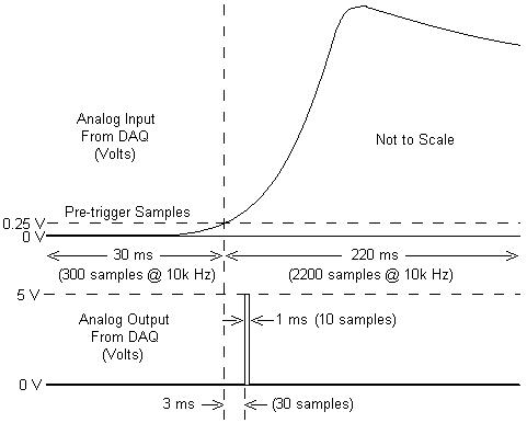
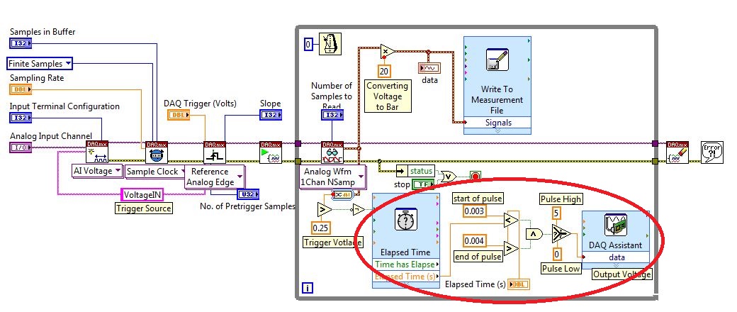
I am working with a combustion chamber and using a system of data acquisition (with the hardware OR SCB - 68) to read the pressure in the cylinder (such as analog voltage). I'm trying a pulse delayed, 1 millisecond to 5 volts of output once the pressure in the cylinder is high above 5 bar (which corresponds to an analogue voltage of 0.25 V). I would also like to record 30 ms samples before the trigger and 220 ms samples after the outbreak. The following image shows visually what I'm talking about.
I created a LabVIEW VI (which is attached), but I keep running into 2 issues:
- When I run with samples finished after a period of time, I get error-200281which I don't quite understand.
- Using the Express VI 'Out of time' to keep time for the pulse I can not get a resolution of 1 millisecond, the pulse is not generated when I put the window between 0.003 and 0.004 seconds for high pulse (i.e. the resolution of 'Elapsed Time' seems to be too coarse).
I'm a beginner to LabVIEW sorry if my questions are trivial or my VI makes no sense, but I was stuck on this during more than a week. Any help would be greatly appreciated!
Thank you
Morgen
This isn't a good way to trigger a pulse.
Use a trigger DAQmx to send the pulse when your acquired signal exceeds 250 mV you specified.See this for DAQmx trigger:
-
How can I get a continuous square wave to the duty cycle of 50% on one of the analog lines?
Hello, I had recently just buy an analog card to our system, and I'm still very new to labview. I have the PXI-6723, and I need to produce a wave square of 0 to 5 volts continuously. I used the square wave generator and used a writing funtion to one of the ports. This produces a momentary wave and that's it. I tried to put some time a loop around the square and watched as wave function. It produces constantly plots, but the write function always has the same thing. If I am the writing inside the loop function I get errors. Any help would be greatly appreciated. Thank you, Fred
Another function to generate the square wave, to change the generation of waveform buffer (the Subvi used) and to connect a control at the entrance to offset from the base generator functions. or simply use the add function on the output waveform.
-
How to convert the analog voltage input form data to True and false (0 = fasle 0: 1-10 = true)
I want to use for LED or photo
10 V to ai0 reciece ex to see the LED or photo on front panel
Help me please
As part of the comparison, it should look like this.
Freelance LV cited above, you must provide additional information to get an apt solution
-
I'd love to upgrade to Firefox 10 you keep offering, but I want to keep all my extensions and Add ons that I so do not lose any after the update. In addition, why so many version jumps in so little time? It was about 2 years ago, you worm. 4, then recently to 5 then 7 and now 10 something like that. Wow so fast.
Seems that you have a user agent that is corrupted by MegaUpload and which identifies you as Firefox/3.0.13
- Mozilla/5.0 (Windows; U; Windows NT 6.0; en-US; RV:1.9.2.27) Gecko/20120216 Firefox/3.0.13; MEGAUPLOAD 1.0 (.NET CLR 3.5.30729;.) NET4.0C)
See:
- https://support.Mozilla.org/KB/finding+your+Firefox+version
- https://support.Mozilla.org/KB/websites+or+add-ons+incorrectly+report+incompatible+browser
- http://KB.mozillazine.org/Resetting_your_useragent_string_to_its_compiled-in_default
Is it Compatible? :
-
Duty cycle of measurement using digital inputs DAQ
Hi all!
My system has a PXI-8269 card and I want to measure the duty cycle of the Digital PWM signal generated by a device.
To acquire this signal, I'll use a digital DAQ (PFIx) instead of a counter of data acquisition (CTRx) (they are already used for other applications).
The search of the database of examples, I found live who use meters. So I wonder if it is possible to do that and how could I.
Thank you!
Sorry, the correct reference is PXI-6289.
I was determined to acquire a digital waveform, converting it to an analog waveform and then using the correct function in the range of functions->-> Analog wave.
Thank you!
-
How can I get the digital power meter?
How can I get the digital power meter?
I use a method similar to the example below to measure the market factor using the inputs of a multifunction data acquisition meter. If the duty cycle is 0% or 100% for a given period, DAQ reading times out and returns an error. In this case, I would get the digital state of the counter of entry so I can put as cycle to 0% or 100%. I want to do it without knowing the digital port and line the entrance of counter... for example I would like to continue referencing DAQ/ctrX since I already have this information.
The application uses an M series: PXI-6229 DAQ and LabVIEW 2011 to make a system customized for VeriStand.
https://decibel.NI.com/content/docs/doc-12396
For the moment I wired the block diagram to add a case structure to check the meter ID and string constants to set the identifier of digital input, as they share the physical connection. As much as I can say that makes the specific code for the PXI-6229 (or any DAQ with only two counters that share connections with p2.1 and p) 1.4
I have attached the VI sub.
When the device is used with a different data acquisition, I can add the connection and/or separate control. Looks like at least one will be necessary given that the meter can only detect the edges... I think it was the piece of information I needed.
Thanks for your help!
-
Hi all
I have never done in time real before LabVIEW and have a pretty simple question.
I know that there is a measure of pulse width as VI in the palette of waveform and it can be used to measure the duty cycle and frequency of the PWM. My question is, is it necessary to use this measure of vi on a platform time pulse width real (compactRIO, compactDAQ etc...) so that it works? In other words, can I just use normal LabVIEW to measure the duty cycle and frequency of the PWM?
Is there an alternative to the duty cycle and frequency of measurement without using compactRIO or compactDAQ platform? My concern is because I did no real time programming and the deadline is tight and there is not a lot to invest in learning programming in real time.
I just want to know the experiences of others who have done it before.
Thank you
Yours sincerely,
chati
Oh yes RT is not really necessary for sample DAQ of things like that. If you have a condition like assess each cycle of a PWM, and if the signal falls then to send a command within the period of a cycle, then you want RT or FPGA to respond deterministically. But if you agree with a bunch of samples taken, then evaluate the data after having been taken then a cheap DAQ card probably will work fine.
Speed can be a matter of concern. Lets say you have a square wave of 1 kHz at 50% duty cycle. If you enjoy at 2 kHz, then you should be able to see that the signal is weak for a sample, then up for a sample and you can determine that the signal is at duty cycle of 50%. But if you have your wave to the duty cycle of 10%, while most of the time, you will see two samples of low, thinking that it's 0% duty cycle, but then from time to time you will get a top and a bottom and get 50% of reading, who don't agree.
This is why it is recommended that you enjoy at a rate at least 10 times faster than your input signal. So if you have an example of signal of 1 kHz to 10 kHz. Then, if your duty cycle is 10%, you will see a small sample of top and 9. But even that might not be enough if you need to have more precision to your measurement. Fortunately, NEITHER sells cheap and expensive material for that. The hardware cheaper that might work for you is the following:
http://sine.NI.com/NIPs/CDs/view/p/lang/en/NID/212383
or perhaps cela
http://sine.NI.com/NIPs/CDs/view/p/lang/en/NID/212384
But you probably want to call OR and describe your situation and they can recommend the best material to use if you are not familiar with their offers. Depending on your situation, you may be able to use an Arduino too. NOR has a toolbox where it can collect samples and send them via USB. The sent message can be the rated frequency and the duty cycle, but once again it is quite limited and does not have any help from NEITHER a material point stand, they provide just the box tool.
-
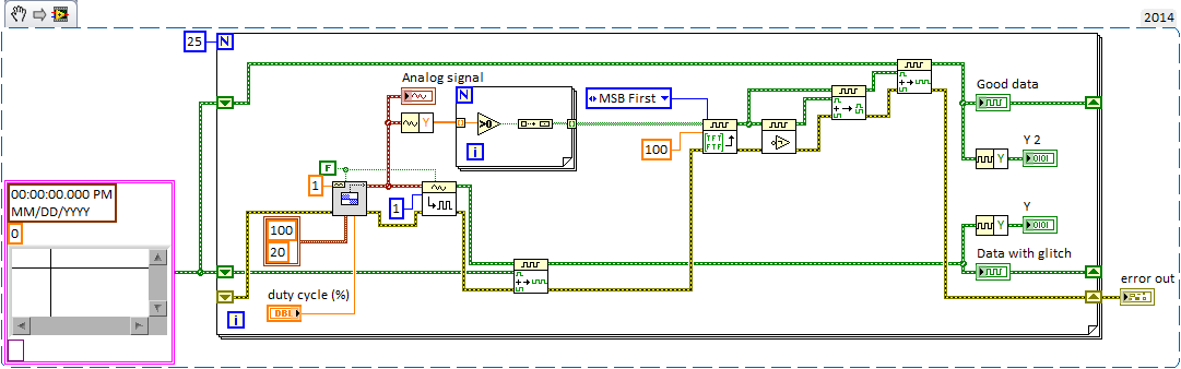
Waveforms digital output duty cycle glitches
I try to use a square wave converted to digital output to operate some solenoids but seeing some problems with the cycle on the digital waveforms. The output frequency will always be of the order of 1 Hz and duty cycle must be adjustable to integer values. I have attached a simplified below, demonstration that shows the digital/analogue output VI I used initially. the problem with this VI, is that if I choose a cycle that is not a multiple integer of my samples for waveform I get seeds. If I use the Boolean digital VI table this problem disappears in my simplified code, but in my real program the problem reappears.
This image shows the waveform analog generated as well as the digital output that results.
In the digital waveforms, you can see that the duty cycle of 50% is sometimes applied during the single loop (~.2us) instead of more than 1 sec iteration, although the curve of actual load indicated in the table at the bottom seems to suggest that LV ignores this glitch (somehow). As I said, the problem disappears if the duty cycle is an integer multiple of the sample/loop. Timing of the loop is torn apart by other e/s to 2 000 Hz/400 samples per loop and 100 Hz/20 samples per loop (large enough VI otherwise I would include it). Obviously, I could change them to get 50% as a multiple, but this does not solve the problem if user needs to adjust from there.
Can someone point me in the right direction here? I'm sure that there is a stupid/easy solution, but I can't seem to get.
Thank you!
You might try turning the inputs A and B of waveform of the VI of the digital samples append. It seems that A should be the fate of the shift register data (the original data) and B should be added (the new waveform) data anyway, at least conceptually.
Paul P.
Engineering applications
-
I use a counter that is generated by a PCI-6110 to switch a relay to solid state that enables or disables a heating unit. I update the duty cycle based on the output of a PID controller (0 - 100 output of PID VI gets scaled to a cycle of 0.001 to 0.99). The question is after two iterations, the written property node is no longer the output of PID on the scale to the task and it seems 0 as the default value.
Many meter generation examples use event structures to detect a change in the duty cycle and pass that to the task. But structures event detect changes in values if the value is written in a local variable and not typed in a CNC? I feel that the answer should be 'Yes'... but in the case I tested it seems to be 'no '.
Don't adjust the precision of a digital indicator / control limits the number of significant digits does a calculation? I would limit my duty cycle to 2 decimal places - i.e. 0.3342 and 0,3313 the two would be 0.33. In this way the cycle is not unnecessarily updated.
The temperature is read by a PCI-4351... which may arise under? blocks if you have not installed the drivers.
arcranda wrote:
Many meter generation examples use event structures to detect a change in the duty cycle and pass that to the task. But structures event detect changes in values if the value is written in a local variable and not typed in a digital control?.
To have a triggered event when a value is changed programmatically, create a Value property node (signaling) and the new value of wire to it. This will trigger a change of value for this variable event.
arcranda wrote:
Don't adjust the precision of a digital indicator / control limits the number of significant digits does a calculation? I would limit my duty cycle to 2 decimal places - i.e. 0.3342 and 0,3313 the two would be 0.33. In this way the cycle is not unnecessarily updated.
.
Changing the properties of display to show only 2 decimal places does not change the numeric value stored in memory. You would have to round up the digital to two decimal places. To do this is to multiply the number by 100, change of an integer (this will lose the remaining decimals), then divide the result by 100 to get again the two decimal places. When changing to an integer, you will need to round to the nearest integer to make 0.3299 0.33.
-
Agilent 33500 B configuration of duty cycle
I use the function generator to Agilent/Keysigt 33511 B to produce a square wave with offset, amplitude and frequency specified. However, I'm unable to set the duty cycle. Is there a VI to control this setting?
Hi jmountney
If you use this driver , I think that there is a function named .vi configures signals Standard Advanced (square) and it has an entry for the duty Cycle, so I think this could help you.
-
I'm trying to find examples of PID controlling the duty cycle of PWM. Is there a simple example? Helps share if you have.
I coundn't find this topic in the viewfinder of the example
Maybe you are looking for
-
Games for Windows Live (GFWL) log: error 80131509
Problem: Unable to connect to GFWL Symptom: Immediate sign in error displaying the error code; «To connect error» Unable to connect. Please try again later. Code: 80131509 " At a couple of old OS (Windows 7 Pro x 64), with all updates. What I tried:
-
I just bought a printer of HP Deskjet 1510 color all-in-one, Scanner, copier yesterday for my father & together he does all this, all the usual things required by the printer... test page, alignment etc. However when I tried a few color prints, color
-
My screen to maximize function is not available for me to use so I can disconnect.
I used uniblue offers scan - and now my screen function to optimize now unavailable to disconnect me. I can only minimize the access - and now I can't use the enlarge click.
-
Get slaves 600EX-RT to fire only via the pop-up Flash
I have a set up as slave and controlled by the 60 d 600EX-RT using the pop-up flash. I have the 60 d settings for the slave to fire single pages 140 and 141 of the 60 d manual. However, in this context the pop-up flash fires again. At the end of p
-
HP laserjet 1020 more usb shared printer being offline
Hello I am facing this problem since two week... I installed a printer hp laserjet 1020 printer win 7 pro. and shared... but whenever the user wants to print it displays offline... "IS THERE ANYONE WHO CAN HELP ME" WILL BE GRATEFUL...