go DC for analog generation with hardware trigger
Hi, I would do the following:
-Together a terminal to user defined voltage CC
-Switch to waveform base voltage generated when a hardware trigger is received
Is it possible to do this with a multifunction DAQ card? I have the impression that seitching of the DC to waveform generation can be done in software. This would lead to some downtime. How long will the dead time? The voltage will be stable over this time?
All comments welcome
Hello Dixie,
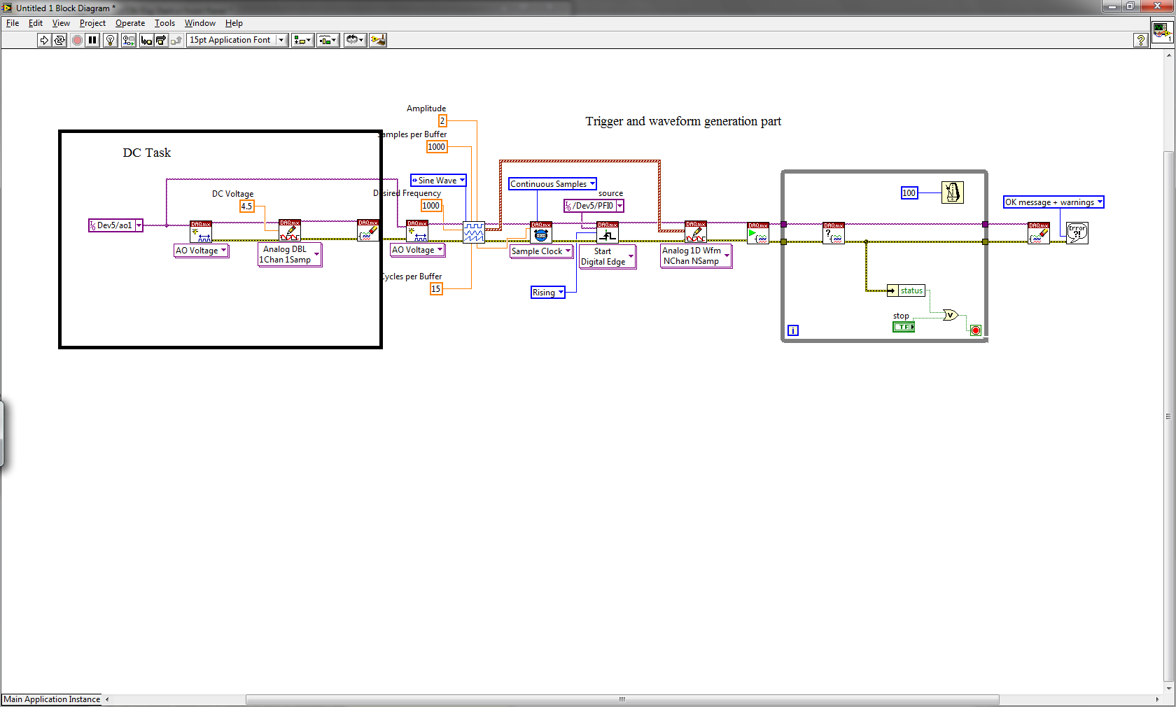
See screenshot of the joint, this could be an option. First of all, you can do a DAQmx task that allows you to send a continuous tension, when you disable directly task the DC output will remain at the level you selected before. Then you create a task DAQmx will send a wave form and waiting for a trigger to do. The output will be at the DC level until there is a trigger so the waveform will be produced.
Casper has soon
Tags: NI Hardware
Similar Questions
-
I use the outgoing/incoming analog DDK with the DAQ 6341 SMU map.
The examples, for example aoex5, show a single timer (method outTimerHelper::loadUI), but the example shows the DMA loaded with same size of vector data.
There is a comment in the outTimerHelper:
 call rogramUpdateCount, which implies that memory sizes different pad per channel can be used.
(the comment is: switching between the sizes of the various buffers is not used)
Nobody knows what should be the format the DMA buffer for data from multiple channels with different frequencies?
For example, we want a0 with a sinusoid at 1 kHz and a1 with a sine wave of 1.5 Khz. What looks like the DMA buffer?
With the same frequency for each channel, the data are interleaved, for example (ao0 #0, ao1 #0; ao0 ao1 #1, #1,...), but when the frequencies for each channel is different, what the stamp looks like?
Hello Kenstern,
Data are always intertwined since each card has only a single timing for each subsystem engine.
To AO, you must specify the number of samples that will be released to the AO. You also specify the number of channels. Because he didn't is that a single engine timing for AO, each AO will be channel will be updated at the same time to update clock tick. Data will be interlaced exactly as shown in the example because each channel AO needs output at each tick of the clock to update. The data itself can change depending on the frequency you want to copy.
kenstern wrote:
For example, we want a0 with a sinusoid at 1 kHz and a1 with a sine wave of 1.5 Khz. What looks like the DMA buffer?
With the same frequency for each channel, the data are interleaved, for example (ao0 #0, ao1 #0; ao0 ao1 #1, #1,...), but when the frequencies for each channel is different, what the stamp looks like?
In your example, you must come with an update rate that works for the two waveforms (sine waves of 1 and 1.5 KHz). To get a good representation of a sine wave, you need to update more than 10 x faster than your fastest frequency... I would recommend x 100 if possible.
Update frequency: 150 KHz
Channels: 2
Then create you stamps that include complete cycles of each wave you want to produce based on the frequency of update. These buffers must also be of the same size.
Buffer 1: Contains data for the sine wave of 1 KHz, 300 points 2 cycles of sine wave
Buffer 2: Contains data for the sine wave of 1.5 KHz, 300 points, 3 cycles of sine wave
You can Interleave them as before. When the data are performed through the ADC, they are out different sine waves, even if the AO channels are updated at the same speed.
-
Synchronize the clocks of 2 PCI cards for analog inputs with e/s digital reference
I'm trying to synchronize the clocks of reference of 2 PCI cards so that the analog inputs are synchronized. However, my appilcation has also digtial e/s on two cards, and who apparently made the mistake DAQmxErrorResourcesInUseForRoute_Routing. This discussion describes a similar problem, but the solution was to just put the reference clock to the slave device, who had no other tasks running on it, so what mine does.
Is there way I can synchronize the clocks of refernce without interfering with the digital I/o?
Thank you!
PS: My application is in C++.
The reference clock is really a lower-level component that is shared by all resources on a given device. All tasks on a given device must use the same reference clock. So if you use DAQmxSetRefClkSrc for a task, you can use it to set the same value for your other tasks.
Best regards
-
Get a hardware trigger on the regeneration of the buffer
Hi all
Is there a simple way to get a hardware trigger when AO regenerates a buffer for continuous generation?
I use NI PCI-6733.
Thank you
Michael
Hi Michael,
I think it would be the easiest way to use your meter to generate a pulse train that uses the sample AO as its source clock. If you know the number of samples that are in your FIFO, you can specify how many samples to make this high pulse and how to make it low so that the total adds to the top to be equal the number of samples you have in your buffer. Here's a good intro bit to generate a train of pulses with a meter. You can also consult the user manual to the 6733 for more information on the functioning of your meter.
Chris W
-
CompactDAQ using to acquire correlated data force-position began with a trigger of digital material?
Hello
up to now, I use a PCI NI6221 card to acquire the data of time - correlation of two analog inputs and an encoder (line A and B), i.e. to get two supply voltages and position for each sample. The beginning of the acquisition is hardware-triggered by a digital line of PFI.
In addition to assessing the encoder inverted /A lines and / b (to eliminate the errors of counting in harsh environments) I want to migrate this task to a CompactDAQ 9172 module with a 9205 (for analog), a 9411 (for incremental encoder signals) and a 9472 (for outputs digital additional static) inside.
My question: is it possible to use the entry PFI0 of the 9205 as trigger of digital material to make an acquisition described above? Or how should I continue?
Best regards
cpschnuffel
I would like to make a correction to my last post... we have actually supported for triggers the 9205 (analog and digital) to any location in the 9172. Digital lines has always obey the same rules I mentioned earlier.
So, you can trigger off the 9205 PFI line in any location, or outside either module in slot 5 or 6.
I'll be sure to amend article KnowledBase that I've referenced once I have the chance to make it clearer and more thorough.
-John
-
PXI-4071 sampling too slow when using a hardware trigger
We use 3 PXI - 4071 s in parallel to measure with accuracy of high voltages. The program is written using LabVIEW 8.5.1.
An additional test condition has been added which requires the use of a quadrature decoder and the synchronous DMM.
We thought it would be simple, using backplane trigger 0.
However, something odd happens.
With a low-cut VI that uses a single DMM, we get 100 microseconds time to sample running with internal triggers. However, if the overall relaxation or trigger of the sample is set to TTL0, the sample time becomes so 5.1 milliseconds. It seems very strange that even just definition of overall relaxation, expected to affect only the time of the first sample, not the time between samples, has that effect. The plug for the DMM also said, that the maximum trigger rate is of 6 kHz.
We have confirmed this reported sample time is independent of the speed of the clock actually connected to TTL0. If the clock is faster, it gets the reported sample time. If it's slower, the samples occur on the edges of the clock.
Does anyone know if there is a parameter that has a default that changes based on the source of command and can be changed to work around this problem, you?
I found the solution to this.
Over time the value-1, the DMM uses a short value (less than 100 US) to set hour when, in modes triggered internally. However, he used much longer (about 5 ms) when the value - 1 and with the help of a hardware trigger.
If the running-in is set to 1e-5, i.e. 10 microseconds, "the estimate" returned for conversion period goes from 5.1 ms 100, we and conversions actually occur at a rate set when clocked with trig 0-5 kHz
-
Output TTL triggers analog input with PCI-6251
Hello, I'm new to LabVIEW and have a question that I hope I can get a response on this forum. I am currently using a PCI-6251 DAQ card with a block of connection BNC-2120. I would like raise an event on an input, for example a sine wave, which is connected to AI0 analog. Then I would send a TTL pulse train via the digital output. What I'm describing can be better understood by the images of this link:
http://zone.NI.com/DevZone/CDA/tut/p/ID/3017
In the tutorial page linked above, they do mention the card PCI-6251, but when I read the specs and compared, 6251 also has analog and digital Board, trigger functions, as well as digital I / Os... so I think he should be able to do what I want it to do. Can anyone confirm this? If anyone could help me by providing a VI that could do what I ask, just to help me get started, would be greatly appreciated. Thank you!
Hello!
Please post on the Forums OR! My suggestion would be to use build it digital Pulse - Retriggerable.vi found in the Finder for example of OR. Open LabVIEW, go to help > find examples > input/output equipment > DAmx > generating digital pulses > generate digital Pulse-redeclenchables. Change the type of trigger for this departure vi > Analog edge and make the source one line APFI (pin 20 of your card is APFI0). This will generate a pulse based on an edge similar to a level that you specify.
I hope this helps!
-
Model generation with USB-6341?
Hi all
We have developed a software quasi multifunction 'device-independent '. This sw is capable of generating the sequence shot timed with the device really used. Up to now, we have used devices PCI-6025 and USB-6221, but now we bought a USB-6341 and when I try to use a message of 200565 error pops up: "specified digital channel contains more bits supported by the version 8 bits of the Port DAQmxBase write.» Use the version of DAQmxBase Port write who takes in charge the broader digital ports. Minimum size of write in bits: 32 "
I tried to change PORT0, PORT1 and PORT2 but only PORT0 is legal for the model generation process and it requires DAQmxWriteDigitalU32 function...
I don't understand why.a / 6341 contains 24 DIO lines
b / only 8 DIO lines are clocked by materialThen there are 24 DIO lines (i.e. 24-bit 32 no!), but only 8 lines are timed by the hardware and I want to use only this 8 lines for model generation!
Our whole software is based on 8-bit pattern-berries (writeArray type is "uInt8"). If we cannot use this structure, we must rewrite dozens of functions...So, how can we use the function of DAQmxWriteDigitalU8 with USB-6341 or what can we do?
Thank you
-George Cs.-
Dear George,
It is an interesting question, which may seem a bit unintuitive at first. The main reason for the 32-bit write operation (although the USB-6341 has only 24 DIOs) is that the functions and the driver support other devices too. As you can see in the manual of the unit (http://www.ni.com/pdf/manuals/370784d.pdf) X Renault series supports digital IOs up to 32 bidirectional signals.
To keep things consistent exploitation of 32 bits is required even if you use only a subset of the available ports.
I hope that this helps to explain.
Best regards
-
If I sell or give my Mini iPad (1st generation) with WiFi cellular (Verizon) can I keep my SIM card? OR once I deleted everything out of the device, the SIM card will be ready for a new user and all my information have also been deleted?
Yes, keep the card. The new owner is their own SIM for the device if you wish.
Make sure you follow all the steps here to ensure that the device is not locked for the new user. What to do before you sell or give away your iPhone, iPad or iPod touch - Apple Support
-
How can I connect an Apple TV to an analog TV with 2 RCA Sockets?
I have an analog TV with 2 jacks RCA - one for audio and one for video. Can I connect to an Apple TV box? Thank you.
Maybe you should try to buy this part, just connect the red plug if your TV does not have one. Here is the link: B01F77KXC0/ref = sr_1_3 https://www.amazon.com/VAlinks-Composite-Transmitter-CONVERSION-Transmission/dp/? ie = UTF8 & qid = 146898...
-
My 7.0.1 program tells me there's an update available, 8.0.1...
I trigger the update that downloads an installation program.
When I restart firefox to get the update installed, restart and triggers a new window indicating that it contacts the server to update. This will continue to get in touch for 30 minutes with no established connection.
To keep my browser to 7.0.1.Windows Vista Ultimate sp2 64-bit.
Try the alternative and more simple way to download from here and simply run
-
Best way to generate a PWM for a stint with LabView2010 and a laptop
Hello
as mentioned in the title, I'm looking for the best way to generate a PWM signal to a relay. I want to use a laptop computer and the LabView2010 for she. I have read through several topics, but after a time that he just got more confused. For example the NI USB-6008 OEM case seems to be a solutiion at low prices, but I don't know if I can use for the generation of PWM signals like this thread says is not possible:
http://forums.NI.com/T5/Multifunction-DAQ/using-PWM-on-NI-6008/m-p/231860/highlight/true#M13339
But then again this thread right here makes it seem as if it was doable:
http://forums.NI.com/T5/Digital-I-O/generating-a-PWM-using-USB-6008/m-p/421654/highlight/true#M5527
Once again in abbreviated form.
What I need:
-the best way to generate a PWM signal to control a relay
What I have so far:
-LabView2010
-Laptop
If possible, it would be good to have two channels for two separate signals, but it is more low importance right now.
Hey Kambra,.
The first thread you mention is correct, you can't make output PWM in any deterministic mode with a 6008. The 6008 is strictly software timed, which means that each digital writing that is done in the unit must go through the operating system and down to the device. And there is a lot of jitter of the involved BONE. The second article you mention says the same thing. They emphasized that they could reduce the jitter of some, but still can not remove it entirely. In the second thread, they mention using a M-series USB device do output PWM deterministic (timed material).
The compromise really down to your application and its requirements. If your application to control the relay requires no determinism, then you can use the 6008. If you need precise control over the relay, try the USB M series.
-
Several analog inputs with different configuration differential/CSR
Hello
Can anyone tell how to measure two analog inputs with different configurations using a USB-6009?
I am aware of the syntax for create virtual channels for the channels DAQmx create virtual so I created two strings using Dev3 / ai0:1 but I would like the first string of the CSR and the second to be differential.
So far I have found no way to specify the configuration of the separate channels.Any ideas much appreciated!
Jack
JackT wrote:
I prefer to use the 'low' level vi is therefore always curious to know if there is a way to set the configuration using the their.
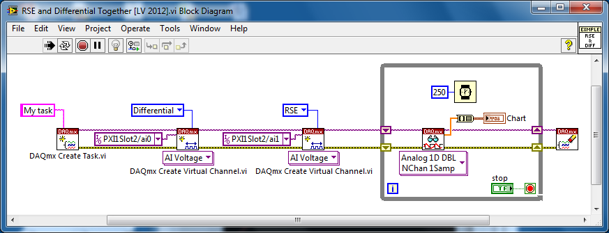
It should be like this:
-
Generate tension with a trigger set
Hello world
I want to ask a general question on the data generation process.
I used "DAQmx start digital dashboard" to set up the task to start generating power on a front descended from a digital signal in my application. My trigger is a train of pulses with a trigger freqeuncy 10 Hz. The build process stops on the front? Or it's just efficient when the first impulse appears and then the signal is generated constantly?
Thank you!
haiyueli,
With a trigger DAQmx start Digital Edge, you will begin your generation when the trigger condition is met (in the case of the falling edge). It will not stop on the front. He will continue to run until it stops in the task, either you stop or a finished generation.
What you reference looks more like a break (example).
-
Software player with equipment trigger events
Hi all
I'm trying to synchronize a number of tasks (software and hardware) to a hardware trigger, where my DAQ (PXI-6259) receives a brief pulse TTL of a box no - PXI elsewhere. I want to listen to this impulse, respond by performing a number of tasks (incl. Configuration of another instrument non - PXI to take a reading via a USB connection to the computer and reconfiguring a switching matrix (PXI-2532)) and loops. It seems that the VISA library can expect a VXI trigger via:
...PXI_status = viOpenDefaultRM(&PXI_driver);PXI_status = viOpen (PXI_driver, "PXI12::12::INSTR",VI_NULL, VI_NULL, &PXI_DAQ);...PXI_status = viEnableEvent(PXI_DAQ, VI_EVENT_TRIG, VI_QUEUE, VI_NULL);...

while (true) {

PXI_status = viWaitOnEvent(PXI_DAQ, VI_EVENT_TRIG, 30000, &PXI_eventData, &PXI_eventHandle);

// Do stuff here. Break if done.

}
and the hardware interrupt itself can be configured using the DAQmx libraries:
DAQmxCreateTask("Epoch Trigger Task",&DAQ_EpochTriggerTask);
DAQmxCreateDIChan(DAQ_EpochTriggerTask,DAQ_EpochTriggerChannel,"",DAQmx_Val_ChanPerLine);   DAQmxDigEdgeStartTrig(DAQ_EpochTriggerTask,DAQ_EpochTriggerChannel,0) // 0 = rising edge
So, my question is how to get the hardware trigger generated since the acquisition of data so that it is detected as a VXI trigger?
Thanks in advance - CDE
Comment of final - I had to change the lines I used on port 1 to a line that I used on port 0, and triggering now works as expected. I have all 326±10 µs delay between the trigger amount front and a pulse response on a separate line (port2.line6). Hope it will be useful for anyone who reads this thread then.
Final code:
// Configure the dummy task to listen for the trigger
DAQmxCreateTask("T_di_ETr",&DAQ_Task_EpochTrigger);
DAQmxCreateDIChan(DAQ_Task_EpochTrigger,DAQ_EpochTriggerChannel,"",DAQmx_Val_ChanPerLine);
DAQmxCfgChangeDetectionTiming(DAQ_Task_EpochTrigger,DAQ_EpochTriggerChannel,                                                  DAQ_EpochTriggerChannel,DAQmx_Val_FiniteSamps,1);
// Wait for trigger signal double timeOut = 10*60; // 10 minute timeout, units of seconds time_t start = time(NULL); while(abs(difftime(time(NULL),start) <= timeOut)) { // individual waiting events have a 10-second timeout (in s). DAQ_Task_Err = DAQmxWaitUntilTaskDone(DAQ_Task_EpochTrigger, 10.0); if ( DAQ_Task_Err >= VI_SUCCESS ) { printf(" Trigger Recieved.\n"); DAQmxStopTask(DAQ_Task_EpochTrigger); break; } else { if ( DAQ_Task_Err == -200560 ) // -200560 = TIMEOUT code { printf(" Waiting for Trigger...\n"); if ( abs(difftime(time(NULL),start) > timeOut) ) { printf(" Trigger Timed Out. Exiting.\n"); break; } } else { printf(" ERROR waiting for Trigger.\n"); break; } } }Only last issue is management of errors in the final version of the code.
Maybe you are looking for
-
I have a laptop Y50 in a few days and I noticed that when I install the drivers for the wifi from the cd provided with the computer WiFi works well but with maximum 72 Mbit connection. When I choose windows to search for drivers more recent it instal
-
People with disabilities control operated even if disabled
I just encountered a small problem which seems a bug to me. If you have a Panel and a knob under the close control, you can close the cover with the Red Cross in the corner, even if the button is disabled! It seems to me that in this case the Panel m
-
Cannot undo changes to display because of the white screen
Laptop Lenovo G510; Windows 7 I'm trying to set up the laptop to an external monitor via HDMI. I tried a setting, but it didn't work. However, the laptop screen went white and now I can't undo the changes. Upon restart, the screen works up until the
-
try to upgrade to win10 stop at 99%
win 10 stop installation @ 99% I uninstalled the GWXUX.exe how retrieve this file or I can I don't know that this is my problem
-
Hi all I need your help on two issues: I can't ping (or get other services) between two computers inside the area. One of them, is configured with the address public and static IP is applied as follows: public static 213.212.a.b (Interior, exterior)