Gradient ellipse problem
Hello!
I followed this tutorial-> https://www.youtube.com/watch?v=ldsTXjQ3rn0
but with my illustrator
and when I got to the step minute 10:27 I block.
Because he built an ellipse with the Red gradient, but I can't make the gradient!
I followed all the steps, but my gradient is red/white! It's not the slope of the video tutorial!
Help me!
Thank you all!
It's my gradient:

It is in RGB mode, you are in CMYK mode
Tags: Illustrator
Similar Questions
-
Greetings...
I'm having a problem with some texts that overlap in a custom list field. In this list box, I am each line drawing and layout on the top left, top right, a line text below and then a text on the bottom. The problem I have is that the DrawStyle.ELLIPSIS are not the... If the text on the top-left and top right are too long, and instead they overlap.
/***********************************************/
/ * * top_left_text top_right_text * /.
/* *** ------------------------------------------------- */
/* *** bottom_text */
/***********************************************/Is it possible that I can accomplish this? I need to use DrawText and I need help texts that are left and right aligned who overlap on the other.
Thanks in advance!
offsetY = (this.getRowHeight() - icon.getHeight()) / 2; g.drawBitmap(1, y + offsetY, icon.getWidth(), icon.getHeight(), icon, 0, 0); g.setColor(ROW_HEADER_FG_COLOR); g.setFont(fontBold); g.drawText(top_left_text[index], icon.getWidth() + PADDING, y + 5, (DrawStyle.LEFT + DrawStyle.ELLIPSIS), width); g.setColor(ROW_DETAILS_FG_COLOR); g.setFont(fontPlain); g.drawText(top_right_text[index], PADDING * -1, y + 5, (DrawStyle.RIGHT + DrawStyle.ELLIPSIS), width); g.setColor(ROW_DETAILS_FG_COLOR); g.setFont(fontBold); secondRow = y + (this.getFont()).getHeight(); g.setColor(ROW_DETAILS_FG_COLOR); g.drawLine(icon.getWidth() + PADDING, secondRow, Display.getWidth() - 5, secondRow); g.setFont(fontPlain); g.drawText(bottom_text[index], icon.getWidth() + PADDING, secondRow, (DrawStyle.LEFT + DrawStyle.ELLIPSIS + DrawStyle.TOP), width); g.setColor(ROW_HEADER_FG_COLOR); bottomLine = secondRow + (this.getFont()).getHeight() + 1; g.drawLine(0, bottomLine, Display.getWidth() - PADDING, bottomLine);How do you calculate the width parameter in drawText calls? What is the full width (less fillings and icon) available or only half of it? This is the only way for drawText to determine whether to use an ellipsis.
To make sure that your text left and right do not overlap, determine the maximum that you want to give one or the other rectangle and pass the correspondent aX, aY and aWidth settings. This width will be different from what you give to the substantive text, as seems to be there alone.
-
Gradient of 'problem' in groups
Hello! We have a problem to apply the gradient effect to a group. It manages the entire group as a single object when it comes to gradient. All other effects is applied per / layer.
Just to show here are the results:
 '
'This is what happens when adding the effect to a group:

It works as it is designed to work. The layer in a group styles are still applied to the whole of the combined buffer and naturally a gradient will change his appearance because the bounding box is used to determine its spread.
Mylenium
-
I'm doing the gradient line up on the curve, if I get a linear gradient even along it. I have created the mesh, adjusted the anchor points, so that they match the shape, I tried to recreate. Then I adjusted the handles of bexier (the "horizontal", not those of the cross-sections/columns) so that the shape is almost perfectly aligned with the original shape. Then, I chose a color for each anchor point, black for the those high and white for down those. Since I want the cuts straight or linear, I did drag the Bezier handles in cuts to their respective anchor points.
The result is the following: http://imgur.com/eDE5V
The gradient is linear to the places, mainly between the sections. But if you look at the low anchor points, you can see that the slope is very linear. In fact, the gradient is as a white sphere around each low anchor point. In addition, the area around the anchor, third from the left and the fifth from the right, is gray rather than black for some reason any. I put all the anchor points in their planned colours - black or white.
Any ideas?
Thanks in advance!
You're a little too complicate it. You don't need so many MeshPatches and so tedious twidling for this object.
The door to a collaboration with MeshGrads (especially when first familiarize yourself with them) is: keep it simple.
'Simple' is a balance. One thing is 'Simple' in terms of use . 'Simple' in real terms construct that results is another. The two often come into conflict.
Says otherwise; TIHE attempt to provide it too much thinking is 'intuitive' use (click on instant-gratification & drag 'ease') often prevents intuitive knowledge of what is happening and gives ugly results.
Understand: The meshes are rectangular arrays of patches. This is why the MeshGrad dialog box asking you to specify rows and columns. Just like in a spreadsheet, each line has the same number of columns. When you draw a shape, then convert to a MeshGrad, you often lose sight of this and end up confused, because the visual appearance of the columns and lines generated automatically does not match your knowledge of the shape.
The same problem occurs when users think auto tracing is a sort of automagic 'conversion '. He have to remember about all these features: the program is not didly your intention and understanding of the form.
Each Patch has four corners. When you leave the program automatically create your mesh, you must try to reconcile your form to what is equivalent to an arrangement of lines and columns. The MeshPoints (corner of MeshPatches) which generate the grad do not necessarily match your anchorPoints of path that define the form. You just think they often do, because the MeshPatches are deformed by an envelope that is trying to match the shape of your path.
So when possible (that it is definitely in your example), start with a mesh object and set then its shape, instead of starting with a shape and trying to force - fit his grad:
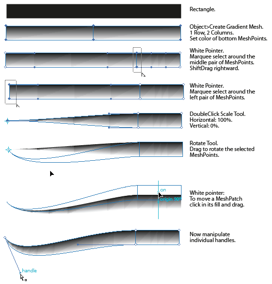
See how much simpler (elegant) is in terms of construction? Note that the patch on the left has still four corners. Just looks like he has three.
Note, however, the ugly triangular facets of the grads. I can't do anything about those. And this brings me to my second main point: why do you feel compelled to create this specific object with a MeshGrad anyway? Just because the MeshGrads are all the buzz, because they are relatively new, it follows necessarily that they are a panacea for everything.
Maybe you're just experimenting to the knowledge of the MeshGrads. If so, it's a good thing. But if this for real actual work, for the specific kind of thing represent you, I got buld probably an Artbrush and end up with something much easier to use, much more versatile, and that more reliable returns from the level "to across-the-form" you want:
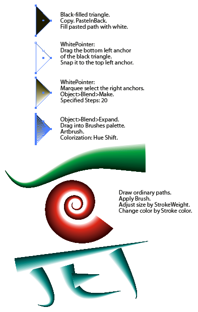
Once the brush is built, using it is a simple matter to draw a path only thorn of any shape, instead of having to draw the contours. On any path to which you apply the brush, color and thinckness is controlled as if it were suddenly ordinary; Simply to apply a different color or weight to Stroke the object.
IE7
-
Melted transitional gradient button problem?
Hello
When I use the color of gradient for melted transition is not a work, it only works with solid colors :/
and I hope that you add the transition of transformation in the next versions of Muse
Wow, that is a bad thing indeed! The Transitions option should either stay unavailable (grayed out) or settings should work. But it's really not nice. Bug alert! With gradients is crucial to the smooth design of buttons...
-
positioning in the new ellipse problem layer
I created the new layer in my document, then a new ellipse within that layer.
I am positioning the new ellipse in the upper layer (vertically) and in the center of the layer along the x-axis (horizontal).
Nothing I have tried seems to move the left object to the starting x position layers (I can move it just fine!).
I'm confused because my high properties and the height of the layer are negative numbers - but when I look at the ruler, all are above zero?
What I am doing wrong in terms of positioning of the ellipse in the layer?
Here is a sample of my script:
var childLayer = currentLayer.layers[j];
var xmin = childLayer.pageItems[0].geometricBounds[0].toFixed(2); // top
var ymin = childLayer.pageItems[0].geometricBounds[1].toFixed(2); // left
var xmax = childLayer.pageItems[0].geometricBounds[2].toFixed(2); // bottom
var ymax = childLayer.pageItems[0].geometricBounds[3].toFixed(2); // right

var newBoneLayer = boneLayer.layers.add();
newBoneLayer.name = childLayer.name.replace(OBJECT_MARKER, "");
var halfOfWidth = parseFloat(childLayer.pageItems[0].width/2).toFixed(2);
var boneGuideXPosition = parseFloat(xmin + halfOfWidth).toFixed(2);
var boneGuide = newBoneLayer.pathItems.ellipse(ymin,boneGuideXPosition, 10.0, 10.0, true, false);

boneGuide.stroked = true;
boneGuide.filled = true;
boneGuide.opacity = 40.0; // set to 40% opacity
var newRGBColor = new RGBColor();
newRGBColor.red = 204;
newRGBColor.green = 255;
newRGBColor.blue = 255;
boneGuide.fillColor = newRGBColor;
-
Is anyone having problems with how Captivate makes degraded after publication? The graphics look good in the project, but the quality is horrible after their publication. I tried to uncheck all the compression settings in the edition menu.
I also tried graphic import uncompressed, and nothing works. If anyone has any ideas or a solution please let me know!
Thank you!Welcome to our community
There are various places in Captivate where you can adjust the quality settings.
* Drag level - look at the properties of the slide
* Project level - look in the Edit > preferences... > project node > size SWF and qualityMaybe modify these settings and will improve your quality. Note, however, that the size of your output file will also increase.
See you soon... Rick

-
Gradients and PDF frame edge problems
I have a document that contains a series of bottles of cutting on a gradient background.
If I print this document to a color printer, it seems.
If I print to PDF, however, all the contours of the block appear (that is, the contours of the block of the cutting cylinders). If I lose the gradient, this problem no longer occurs.
Someone can you please explain how to solve this problem (and why it is happening at first)?Thanks in advance.
In rereading the post, can I have misinterpreted what you said originally (a screenshot is a wonderful way to show us what you're talking about). I thought you said the transparent background area showed as a different from the rest of the background shade, but I realize now that's probably not what you mean at all.
First turn off we're going to try to get more details on the file and the final outing. This will display a press or digital? Are the Spot color or process?
What are the settings you use to make the PDF? You said 'print' in PDF format, and if this is the case, you're flattening transparency and what you desbcibe as showing the outlines of the block would be thin white lines in the image inclusive. They are called "seams" and are a flattening artifact that displayed on the screen and in low resolution prints made since the PDF, but don't generally are not in press output.
Print to PDF is a distillation process and ALWAYS made PDF with flattened transparency. It is best to leave transparency live as long as possible, ideally let RIP printer do the flattening. To keep the dynamic transparency, you must EXPORT it to PDF, not print (and starting in CS5 you for printed output, you must change the default value to [Interactive] PDF export as PDF [Print]) and using Acrobat 5 or greater compatibility. Presetting of the quality press is a good choice if you are going to press on and you control the color management on your end because you know the printing requirements (it converts all colors to process and a unique output profile). PDF/X-4 will preserve all the colors and incorporated to the RIP printer profiles for color management, but not all printers are up-to-date enough to handle this.
-
Gradient banding external change from Lightroom 6-Photoshop CC to ProfotoRGB
I think I discovered a sort of fix regarding banding degraded in CC of Photoshop, but I don't know if there are traps in the changes I made.
When I edited an image with a gradient in the background (that I created with studio lighting) in Lightroom 6 with ProfotoRGB as my color space of mounting external and modified in Photoshop CC, I had severe banding degraded on the bottom. However in Lightroom there is no gradient banding.
After search in this forum, so I changed the ProfotoRGB external editing preferences SRGB color space in Lightroom and voila there is no Gradient banding at all in Photoshop CC.
Before I did it, I mess around with cache levels (which are now 4) and cache tile size (which is 1028 k).
Can I keep the external change in Lightroom as SRGB, but keep my workspace as Profoto RGB in Photoshop? Or do I have to match?
It's funny that I have the gradient banding problem when editing external Profoto RGB (I right click on the image in Lightroom and go to Edition in), is this a known problem and there will be a fix for this?
Thank you very much
Shadow proPhoto banding is a known problem that has existed since at least CS5. It only affects the ProPhoto files when the graphics processor is set to 'Normal' or 'Advanced' in the preferences.
If the options are either to avoid ProPhoto (Adobe RGB is very good), or place GPU mode 'Basic '.
The problem was reported here and elsewhere repeatedly. Engineers Adobe said at the same time they would look into it - but it's still there. If the problem is in video/OpenGL driver code is probably not much they can do.
-
Gradient, stuck for hours problem
Hey all, I'm a little new to this forum, but I tried to do something that doesn't turn out to be the way it should be.
So I read a few tutorials on the use of gradients on several forms, making it as a compound path. However, somehow I get it with this particular item I m do.
This object has many forms AND a path already. Sorry if this is huge.
Link to the .ai file: http://www.debeeronderneming.nl/test/Hourglass2.AISomeone knows something to solve this problem?

On the new file:
1 shift click with a selection tool on the ellipses which are the tops of the hourglasses and press Ctrl + 2 to block
2 lock all the layers except the layer 1
3. using the selection tool, drag a marquee around an hourglass and press Ctrl + 8 to make a compound path.
4. Repeat step 3 for the other two hourglasses.
-
Printing a document in indesign that contains an eps logo. Part of the logo is not printing, but shows a white circle instead of a ball with a gradient. I think that it is an overlay problem - can anyone help please
Try to resave the EPS to the native .ai or .psd format (depending on whether it's raster or vector) and use it.
-
Problems with gradient fill. Do not know how to choose the gradient circles between outer circles still especially when there are more than 3 colors.

Hello
It should be a little easier than trying in landscape orientation. Who help me?
Thank you
Ignacio
-
What is the problem with the conversion of objects with gradients to the gradient mesh?
What is the problem with the conversion of objects with gradients to the gradient mesh?
Radial gradients are special, and it could become difficult edit the gradient mesh resulting.
Take the layer apnel and inspect your objects. You will find a clipping mask the cracks inside.
-
CS6 PS 16bpc shape burst gradient of transparency problem
Hello
Huge first post, I tried to keep it concise, thanks for reading.
The combination of:
(1) image 16bpc. that contains a non-empty layer with the layer style to:
(2) race: shaping Burst: degraded; and
(3) transparency in the gradient (red > semi transparent white) race:
causes the entire race to make transparent. Changing one of the points of (1), (2), or 3) causes the entire race visit as planned. For example, starting with an image with this combination of shape/16bpc burst/transparency in the gradient:
-just hang out to 8/32bpc 16bpc renders the stroke properly. Switch back to 16bpc, the stroke becomes transparent.
-just burst radius shape correctly renders the stroke (in the radial direction). Return to the rafale form renders the transparent stroke.
-simply by changing the solid red gradient > white Uni renders the stroke properly. Change the solid red gradient > semi transparent white restores the all transparent stroke.
8bpc + burst + transparency in the shape gradient = correct, partially visible
8bpc + burst + solid shape gradient = OK, visible
8bpc radial + transparency in the gradient = correct, partially visible
8bpc + strong + radial gradient = OK, visible
16bpc + burst + transparency in the shape gradient = incorrect, transparent
16bpc + burst + solid shape gradient = OK, visible
16bpc radial + transparency in the gradient = correct, partially visible
gradient radial + solid = OK, visible + 16bpc
32bpc + burst + transparency in the shape gradient = correct, partially visible
32bpc + burst + solid shape gradient = OK, visible
32bpc radial + transparency in the gradient = correct, partially visible
32bpc + strong + radial gradient = OK, visible
Comments:
-The race is still there in this combination, such as applying also a shadow reveals the drop shadow is offset a distance by the thickness of the line, it makes it just completely transparent race.
-The layer itself and the other layer styles are still visible.
-C' is 100%/Actual Pixels (since it is sometimes a question). Interestingly, lower zoom of ~ 60%, the race renders correctly, but zooming in again, it becomes transparent. Navigation preview renders the stroke correctly at all zoom levels.
-Flattening/pixelation still renders the transparent stroke.
-Ditto for new/existing/duplicate files.
-Ditto for sRGB/ProPhoto/no managed.
-Even after purge
-Even after rebooting.
-Ditto for PSD/PSB.
-Ditto for the x 32 (on Win7x64) and x 64 (on Win7x64).
-Ditto for the disabled/enabled reduced GPU.
I have a workaround, change of the slope, for example:
Fixed red > red transparent; TO
Fixed red > white Uni; and the blending mode to linear density parameter.
It is very annoying, however, and is not always look the same. I'm conversion ~ 400 8bpc multi-layer psd 16bpc to eliminate a problem of widespread banding (several layers, gradients, masks, degraded and degraded styles), number with this combination. The conversion was easily addressed by lot for the 8 > 16bpc part, but lack the layer styles in this combination. Layers with this solution to workaround/combination of treatment must be done manually through combinations of different colors, orientations, amounts, etc. They are all unique compositions with little similarity.
Flattening/merge layers in 8bpc first to preserve the race and then by converting to defeats the purpose of the conversion of 16bpc 16bpc to eliminate banding.
Similarly, I use 32bpc Smart layers to these layers, but that means still to find the offending manually layers.
Last resort I tried to convert in 32bpc, but some of the most exotic fusion used styles are not available in 32bpc; the files are already huge, some of them PSB, is another factor. and I have a lag of contrast when you convert 8bpc to 32bpc which does not occur during conversion 8bpc > 16bpc (they were initially created on a monitor not profiled with colors unmanaged [error made during the transition from sRGB CRT > wide range LCD]).
Thanks for reading.
CS6 Mstr Coll PSx32 | PSx64 Win7x64 16 GB i5-750 GTS 250 1 GB
That seems to be and has been a problem for many versions of photoshop, at least from photoshop cs (photoshop 8) leave.
Yes, I tested in photoshop cs and seems to do the same in 16-bit/channel with a stroke: shape gradient burst with transparency.
You could report it on the
-
Problems with rendering shadows and gradients in folios Android
Does anyone have experience or solutions on how to solve a problem with damaged feathers, transparency and shadows in the "renditions" Android/folios?
In the interpretation of the iPad (1024 x 768), there are several frames scrollables, multi-state objects with transparencies and gradients etc. When it is seen on Android devices, if specific rendering of the iPad or Android rendered, it restores transparency, gradients and shadows as a white tone and that he is not rich somehow.
Is this a known problem or there at - there a way around this?
Is this problem resolved when you change vector to Raster (or vice versa)?
Edit: To add a color to this, we have an old bug that we decided to not no difficulty last year titled: "Display of MSO with transparency applied is different with 'Pixelated' and 'Signifying' at the discretion of MSO." Looking at the details of this bug, it seems to be exactly what you are light (whiteness in transparency on vector), so I hope that my question above translates a work around.
Thank you
Dave


Maybe you are looking for
-
Is it possible to disable the options how to open since the new update?
I hate how the options will open in a new tab instead of a new window. Is it possible to turn it off so that the options will open in a new window as before?
-
After OTA update notification volume
After updated g4 + last update of software, I see major problems are solved, but volume of notification is not as strong as before. Although the ring volume is ok
-
Satellite P300-190 - can't find the stereo mix in the sound settings
Hello Maybe this question is posted before, but I can't seem to turn on the stereo mix option in my sound settings.It simply isn't there. Does anyone know how to fix this? Or is it not possible.
-
Y560 switchable graphics do not work
Hi all I have the model of i5 y560 WITH switchable graphics, however, sometimes it does not. Basically when I try to switch from graphics using the switch of the money up front, there is no response. I even tried to right click on desktop and try to
-
I would only delete personal files.