How to build a parser of vector signals PXI using different module combinations
Normal
0
21
fake
fake
fake
PT - BR
X NONE
X NONE
MicrosoftInternetExplorer4
/ * Style definitions * /.
table. MsoNormalTable
{mso-style-name: "Table normal";}
MSO-knew-rowband-size: 0;
MSO-knew-colband-size: 0;
MSO-style - noshow:yes;
MSO-style-priority: 99;
MSO-style - qformat:yes;
"mso-style-parent:" ";" "
MSO-padding-alt: 0 cm 0 cm 5.4pt 5.4pt;
MSO-para-margin-top: 0 cm;
MSO-para-margin-right: 0 cm;
MSO-para-margin-bottom: 10.0pt;
MSO-para-margin-left: 0 cm;
line-height: 115%;
MSO-pagination: widow-orphan;
font-size: 11.0pt;
font family: 'Calibri', 'sans-serif ';
MSO-ascii-font-family: Calibri;
MSO-ascii-theme-make: minor-latin;
MSO-hansi-font-family: Calibri;
MSO-hansi-theme-make: minor-latin;
mso-fareast-language: EN-US ;}
I understand
Vector signal analyzers OR consist of 2 or 3 separate PXI modules: 1
digitizer, 1 buck converter of RF frequencies and 1 generator of signals (model 5663).
1. can I use digitizer and signal
generator general purpose oscilloscope and generator of signals separately?
2 may I build my own VSA by choosing
different combinations of scanners and the signal generators? Or replace the signal
generator by an arbitrary signal generator?
3. I
intend to buy a digitizer/oscilloscope and an arbitrary signal generator
analysis of response of frequency on the transformers. Later I plan to
buy a step-down converter frequency and build a vector signal Analyzer. Is this possible?
Hello
The frequency IF the 5660 and 5661 (it's the same thing) is 15 MHz, with an instantaneous bandwidth of 20 MHz. The difference between the 5660 and the 5661 is located in the digitizer that accompanies it. The 5660 uses the PXI-5620 digitizer that has a sampling rate 64 MECH. / s and a buck converter of digital frequency limited to 1.25 MHz of bandwidth. The 5661 uses the digitizer PXI-5142, giving you a MECH 100. / s rate and a PSO allowing digital downconversion circuit and the decimation of the full bandwidth of 20 MHz.
The common comment in the SBA above is the RF PXI-5600 frequency step-down converter which is a superheterodyne architecture of three floors. OL is for the three stages of this module are auto-approvisionnées in their own country. The architecture of several step allows for rejection of the improved image and filtering at the expensive of a noise floor slightly higher due to the signal path more complex. There also an OCXO on board, this gives him a time reference more precise - noise reduction phase etc. The PXI-5600 by itself is wide from three locations.
The SMU-5601 since SMU-5663 step-down is designed based on the single frequency step-down converter and resumes from a single location. The celled frequency step-down converter gives you improved noise floor characteristics and a better dynamic range, with the rejection of the image fees, having does not simply because there is only one step. The LO is provided by an external module in this case for several reasons. Have a separate external LO allows more modularity in your system, as well as the ability to share a single LO generator between several vendor-specific attributes. This opens the possibility of MIMO applications. The internal of the NI PXI-5600 LOs are not shareable and therefore cannot be synchronized between several PXI-5600 s. The PXI-5663 (all three modules) takes up the same amount of space in the slot as a single NI PXI-5600 without a digitizer.
The PXI-5154 is indeed a powerful scanner, given its instantaneous bandwidth of 1 GHz. Remember, however, that the connector Active Directory on this digitizer is 8 bits, compared to the 5622 which is 16-bit. If you need more resolution is of course entirely depends on your application. The PXI-5600, as SMU-5601 is controllable as a buck converter stand-alone frequency using the DAMA API OR. You will need to program your application with the scope API for use with PXI-5154 OR and the API de DAMA. A few other caveats to note is that there is no PSO on the PXI-5154 so you can't enjoy the Equalization filter to correct the frequency of the NI PXI-5600 response. Also, as I mentioned above, the frequency of YEW of the NI PXI-5600 has 15 MHz with a bandwidth of 20 MHz - processor 1 GHz bandwidth on your digitizer will be somewhat of an overdose of the IF signal.
While you're dead on with the advantage of modularity, I would take the time to really meet your search application and ensure that different choices of module and their combinations to meet these needs.
Hope that helps!
Tags: NI Products
Similar Questions
-
How to build a drag and drop multimeter lead using Flash animation?
I'm building a virtual multimeter to test simulated circuits. I would like to be able to drag a lead animation test multimeter to a circuit point and drop it on a target. The static drag and drop is not my problem. I would like some suggestions on how I can animate the movement of the head itself. Any suggestion would be appreciated.
you want something to "follow the mouse", but do not be dragged?
If so, use a loop (enterframe) and facilitate the position of the object with the mouse:
Object.x += speed * object.x +(1-speed) * mouseX;
-
How to build finance balance sheet as user interface using the ADF Faces component
Hello
We know that financial balance sheet will have a calculated field, imaging of the last row will be the value of the sum for all above each column (see below the very approximate example), I doubt that ADF Table is the faces component appropriate to have a quick idea on this? Thank you
1 point | 10. 10. 10. 10. 10.
2 point | 20. 20. 20. 20. 20.
sum | 30. 30. 30. 30. 30.
-Liang Yi
It is possible in the ADF. See below how you can add a sum calculated lines.
http://rohanwalia.blogspot.in/2012/11/ADF-Groovy-for-total-sum-of-column-in.html
You can extend the same approach in your use case.
Thank you
-
Application of a policy of VSG when the vector signal generator is offline?
How policies are applied when a vector signal generator is offline, make port profiles with an attached policy start VSG to abandon all traffic until the vector signal generator comes back online?
VPath and vServices configuration
The default value of failmode is close.
Fail mode specifies the behavior when the MEC has no connectivity to the service node. The default fail mode for ASA 1000V and VSG is narrow, which means that the packets will be dropped. The default failure of vWAAS mode is open, which means that the packets will be passed. service nodes vPath 1.0 does not support service chaining. When you use a vPath 1.0 service node in a string, traffic to that node goes into failure.
Thank you
Responsible Dan
Cisco IDP data center
You want to know more about how the PDI can help you?
http://www.YouTube.com/watch?v=4BebSCuxcQU&list=PL88EB353557455BD7
-
Analyzers of vector signals OR, in real time of tektronix and tests EMC spectrum analyzers
Normal
021
fake
fake
fakePT - BR
X NONE
X NONEMicrosoftInternetExplorer4
/ * Style definitions * /.
table. MsoNormalTable
{mso-style-name: "Table normal";}
MSO-knew-rowband-size: 0;
MSO-knew-colband-size: 0;
MSO-style - noshow:yes;
MSO-style-priority: 99;
MSO-style - qformat:yes;
"mso-style-parent:" ";" "
MSO-padding-alt: 0 cm 0 cm 5.4pt 5.4pt;
MSO-para-margin-top: 0 cm;
MSO-para-margin-right: 0 cm;
MSO-para-margin-bottom: 10.0pt;
MSO-para-margin-left: 0 cm;
line-height: 115%;
MSO-pagination: widow-orphan;
font-size: 11.0pt;
font family: 'Calibri', 'sans-serif ';
MSO-ascii-font-family: Calibri;
MSO-ascii-theme-make: minor-latin;
MSO-hansi-font-family: Calibri;
MSO-hansi-theme-make: minor-latin;
mso-fareast-language: EN-US ;}1. how to work if vector performance of or
Analyzers of signals compare to Tektronix real-time spectrum analyzers?2 can you emulate Tektronix FFT
processing overlapping?3. is it possible to use vector of NOR
Analyzers of signals of compliance EMC and/or test preconformite? Is there some
companies use it successfully? Need a special or custom software?Thank you
Hi emc2006
I'll answer your questions separated by your topics:
1 - What is the factor that you want to compare between these two products? In the link below, you will find the performance of the NI PXI-5660 RF Signal Analyzer system.
2. you can develop this feature of programming in software Application development, i.e. of LabVIEW.
3. Yes, NI´s vector signal Analyzer could run preconformite or EMC compliance analyses. In the same link below, you will find in the subdivision of Applications.http://zone.NI.com/DevZone/CDA/tut/p/ID/4298
Concerning
Napoleao
Application engineering
National Instruments -
How to check the power of the signal to an extended airport
I have 2 Airport extreme. (new 802.11ac versions)
We're at the bottom, connected to a cable modem, and the other is implemented as an extension to the floor.
6.3.6 Airport utility I can click on a base station and place the cursor on a connected client and see the quality of the connection to this computer / iOS device.
I would like to see the quality of the signal to the base station to the floor, so I can move it around to get the best signal.
Is it possible to see this value? The only thing I can think to do is to stop the base station to the floor and move a laptop or iPhone around up there and check it is the strength of the signal and take the strongest spot is the best place to put the Extender.
Thanks for any help.
If you point to a connection, it should show some details. Where mine says excellent.

Of course, the old utility was much more useful. It will give you signals at both ends... and you can start a second screen and put them side by side. Subsequently is not always better in Apple utilities...

If you do a google search 5.6.1 utility yosemite
You will find how to install it... work on el capo as well.
Is it possible to see this value? The only thing I can think to do is to stop the base station to the floor and move a laptop or iPhone around up there and check it is the strength of the signal and take the strongest spot is the best place to put the Extender.
The use of the office phone or laptop running a wifi Analyzer is also a very good way to do it... the signal is not different... in other words the place that is best for one device will be also the best for another... This also gives you a way to attach numbers to signal loss in any particular area.
-
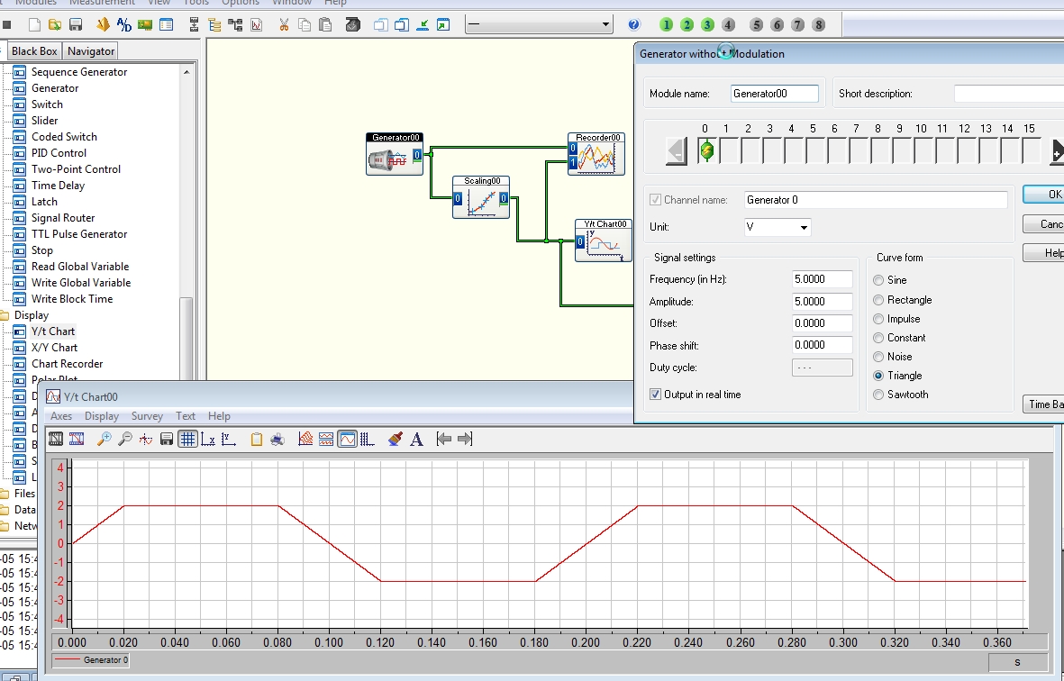
How to build a square with a slope (talud-respons)
Hello
I want to generate a signal (square with a slope) you can see what I mean in the picture.
With:
period is: 0.2 s
rising edge: 0.04 s
falling edge: 0.04 s
I can't find how can I do such a signal with the signal generator, how do I do such a signal with modules available in DASYLab?
I hope someone can answer question
Thank you
If you do not Pro, you may be able to use the module generator with a triangle wave and then use the scale to cut the upper part, to make it more like a trapezoid.
A wave of Triangle of 5 Hz with an amplitude of 5, limited to +-2, will do.
-
generation of carrier multi using vector signal generators OR
Dear all,
I have a client who asked me about the capacity of the vector signal generators OR to generate signals porters multi, and if yes, what will be the minimum displacement between adjacent channels? There already buy a complete RF PXI system of NEITHER and I need to support as soon as possible
also, if I can work on the 2.7 GHz or 6.6 GHz to test GSM and CDMA2000 1 X RTT units?
can someone help me in this please
I'm in a hurry!
Mohammed,
Since VSGs of NOR are all software based, you can generate practically any signal you want, as long as it is within the bandwidth and dynamic range of the instrument. The SMU-5672 generator has a bandwidth 20 MHz, and the SMU-5673 real-time has 100 MHz of bandwidth of generation. You can create your MULTIPORTEUSE waveform in software and set the way you want.
Each platform is able to test GSM and CDMA2k. I would recommend the platform 6.6 GHz for test times improved if it is for the production. Implementation of the Protocol can be a challenge, however. If you have a great opportunity cell phone, you should get in touch with your field sales engineer OR to see if EITHER can provide any help.
-
How to build a table of TDMS file open
Hello
Examples NI TDMS - Express write data .vi (time domain), I can build a PDM file with 2 channels (sine and square waveforms) data, which are stored as test.tdms.
Using Express read .vi data (time domain), 2 channels of waveform data are read. How to build a table later? How to separate the 2 channels of data in the tables 1-2 and manipulate the data using table functions?
For example,.
I want to collect 100 from index100 between channel 0 and their average. I want to take 50 samples from the channel 50 1 index and double each element.
Thank you for your help.
Hey Bing.
You can perform operations on different channels in the 2D table using the table to index. This will allow you to choose the channel to operate on, then you can perform the operation inside a loop on each element. In the included code snippet, I used a shift register to find the total cumulative values in channel 0 and then divided by the number of samples.
I recommend you read some tutorials LabVIEW and bases of knowledge on topics that are related to yours. These could help a lot.
I hope that my suggestions help,
Chris
-
How to build a table using incoming data stream?
I'm programming in VBAI but use LV as my Interface of Inspection. The VBAI program will go into a finite loop (x 1000) and the digital indicator with dbl vaule of food in front of the LV Panel if the value double is in order.
In LV, how to build a table (index 0-999) with this stream?
-
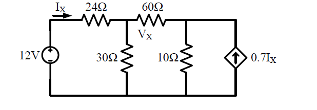
How to build the current controlled current source
I want to check my solution using multisim, however, I don't know how to build a circuit containing the current controlled current source. Hope someone can help me. Thanks in advance
.
The current direction must be placed between the the + 12V and 24 ohms resistance.
I just made the circuit and if you make the change, you will see that you are right in your calculation.
-
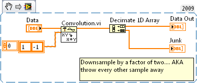
How to build a {+ 1, -1} by wavelets?
I am using labview 8.6 and the statement calls for me to "convolve data with Wavelet following {+ 1, -1}.» How to build this Wavelet?
Thanks for the help.
-T. Vepa
Something like that
-
How can I send more than one signal to DMA FIFO?
Hello
I am trying to send more than one signal to DMA FIFO, but I don't know how to do. I have no problems when I send a signal. I try to use a DMA FIFO block for a single signal. For example if I have 3 signal I use · FIFO of DMA but when I want to wath them a table waveform signals have a delay.
How can I do to send more than one signal to DMA FIFO? and if this is not possible, how do I do to syncronizate 3 signals?
The data type of the signal is FXP<16,10>
Kind regards.
Pablo
-
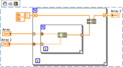
How to build the table with all the combinations of a source table?
Hello
I have a 2D array that contains the list of the power user-defined settings. The number of PSs (table rows) is not fixed. For example - 3 PSs:
Stage of Min Max name
PS1 3.0 3.6 0.3
PS2 0.9 1.2 0.1
PS3 1.7 1.9 0.1
I need to build, from this list, a table of all the combinations as below:
PS1 PS2 PS3
3.0 0.9 1.7
3.0 0.9 1.8
3.0 0.9 1.9
3.0 1.0 1.7
3.0 1.0 1.8
3.0 1.0 1.9
3.0 1.1 1.7
3.0 1.1 1.8
3.0 1.1 1.9
3.0 1.2-1.7
3.0 1.2-1.8
3.0 1.2-1.9
3.3 0.9 1.7
3.3 0.9 1.8
3.3 0.9 1.9
3.3 1.0 1.7
3.3 1.0 1.8
3.3 1.0 1.9
3.3 1.1 1.7
3.3 1.1 1.8
3.3 1.1 1.9
3.3 1.2 1.7
3.3 1.2 1.8
3.3 1.2 1.9
3.6 0.9 1.7
3.6 0.9 1.8
3.6 0.9 1.9
3.6 1.0 1.7
3.6 1.0 1.8
3.6 1.0 1.9
3.6 1.1 1.7
3.6 1.8 1.1
3.6 1.1 1.9
3.6 1.2 1.7
3.6 1.2 1.8
3.6 1.2 1.9
How to build this table programmatically?
(Note also that the number of rows in the source table is not fixed).
Thanks in advance!
Hi Berezka,
using a magic of automatic indexing:
-
Build an html5 app, I only .html, .js, images, css file folder files / files. How to build a web app/html5 app in that if I did not file config.xml?
I downloaded the game codes and try to build games using these codes, but I had only
data folder
image folder
js file with .js files
file .html
main.js file
In this case, how build/package web app /html5 app if no config .xml given?
You will need create your own file config.xml. There are samples and documentation on each of the items on our microsite here:
https://developer.BlackBerry.com/HTML5/documentation/gold/working_with_config_xml_file_1866970_11.ht...Note that all the elements in the samples are not necessary. For each piece, make sure that you actually need in the config.xml file. For example, most web game conversions will not need
elements (using the old SDK) since they make use of BlackBerry-specific APIs.


Maybe you are looking for
-
How to remove a mozilla plugin class file that I can't remove
I have this file showed up in one of my folders. It has just a name of another file stored there, but with the extension/type TSMozillaPlugin class and I can't remove it somehow, I get the message that the file is gone. The file size is 0 and that al
-
I lost the entire Firefox application when upgraded to 4.0 I use a G5 Mac version 10.4.11
Often there are upgrades offered when I opened my Firefox and made automatically. This time with the 4.0 upgrade offers I messed up and lost the entire application (my Firefox icon with a sign stating that he is not here.) Help.
-
ICloud on Web Mail vs. Mac Mail in applications
ICloud on Web Mail has a tab From from one alias, but Mac Mail (the application on my MacBook Pro) does not have a tab (only a response to the tab). How to use my iCloud alias without having to go to the web version of iCloud?
-
"Smart Print" & MacBook Pro
I just bought an OFFICEJET PRO 860 by hp and downloaded Smart Print. However, I think that Smart Print does not work with the iMac or MacBook Pro. Is someone can you please tell me if my feelings are correct. I can't download to work. Yo thanks fo
-
OfficeJet 6700 Premium: Print color in black and white and then back to the color?
I figured out how to disable printing in black only, but I can't restore color. Any ideas?