How to generate a pulse signal?
Hello
I'm relatively new to LabVIEW and I need to generate an impulse (Dirac function) in the motor continuous. At the same time, I need to be able to change the pulse width.
I am currently using LabVIEW 7.1.
Hey,.
With your E-Series cards, you can counter to generate impulses for the user.
The best way to find examples using the Finder example under the Help menu of LabVIEW. Simply navigate to the e/s material > DAQmx > Counter > generate signals or search for pulse generation.
Tags: NI Software
Similar Questions
-
How to convert the pulse signal line single layer
Hello
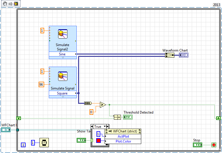
I tried to create a VI that will allow me to convert a pulse signal (generated by a tachometer) in a line single layer, indicating that a revolution succeeded. I would like to overlay this line on other signals generated.
I am able to detect the falling edge of the signal, but I could not make a suitable line. I tried to create a new waveform, and juggle the markers, but no method worked for me.
Does anyone have ideas for a good way to do this?
Below is my test VI.
Make the second vertical lines style trace (trace style: no points, no interpolation, fill - inf). a NaN whener you don't want a power cable and a '+ inf' when you want a vertical line.
Here's a simple example:

-
How to generate a pulse with the signal generator?
Hello
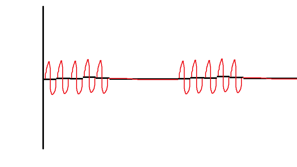
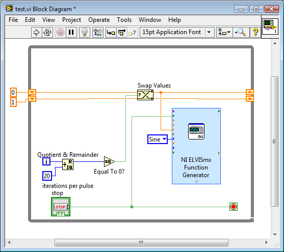
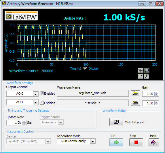
I would like to ask if anyone knows how to use the Elvis platform to generate a regulated pulse wave?
It should look roughly like the picture above. A sine wave with the regulation.
Anyone who can answer my question please respond to my post.
Thank you.
You are using LabVIEW to generate the waveform or using the Soft front panels? In LabVIEW, you can use the express VI generator function and specify the Type as "Sine". Then, simply change the amplitude of the sine wave. During the actual pulse, the amplitude would be what you want (i.e. 1 V) and while the pulse is idle, set the amplitude to 0.
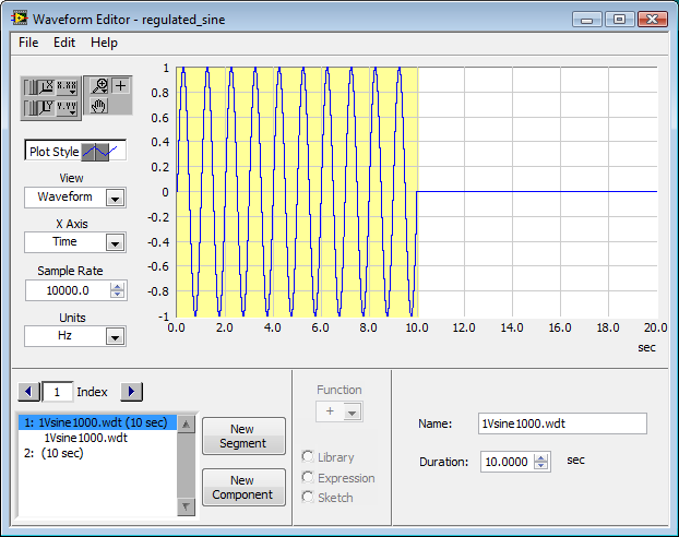
If you use the soft front panels, you can use the Waveform Editor to create a waveform that includes a sine wave for the length of your pulse and then the values of '0' for the rest of the time. Then use this waveform in the flexible front of the arbitrary signal generator. Simply create a component of sine as the first part of the wave and then add another element to a level DC '0' for the rest.
-
Generate the pulse signal signle on the digital output line
Hello
I am now writing a program using c# and DAQmx.
I have a NI PCI-6514card and I want to send a signal for half a second to a single line of output.
I know how to write online by using the DigitalSingleChannelWriter object, but I want this signal, disappear after a period of time.
Thanks in advance for your support.
J.. Gasser
One thing is certain:
C:\Users\Public\Documents\National Instruments\NI-DAQ\Examples\DotNET2.0\Counter\Generate Pulse\GenDigPulse\cs
It is on Vista.
On XP, I believe that the path is:
C:\Documents and Settings\All Users\National Instruments\...
-
How to generate two pulses per cycle? PCI-6251/6255
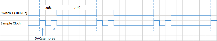
Hello. I want to generate two or more pulses per cycle like the timming diagram. This pulse will be used to trigger the sampling data.
I am ussing the PCI-6251. The VI examples to counter outputs can easily generate the first line, but the second I have no idea. All information can help.
Another problem could be the synchronization of this lines and data acquisition.
Concerning
Ivan C.
I would like to use the digital outputs for this - just generate a continuous at 1 MHz clock using one of the counters and write the following in your digital output lines:
H H H L L L L L L L
H L H L L L L L L L
If you want to use these signals to pick a different spot on the 625 x, you the output of wire in a PFI lines.
Best regards
-
How to generate a digital signal on a negative slope of the clock?
Hello
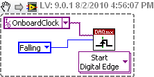
I need to get out a finished length of the Digital pulse which will begin on request to the negative of the clock slope import (or export).
I try to get the clock, exported or imported, but in any case, I can trigger output signal on the negative slope.
What is the trick?
Thank you
Pawel
What camera you use to build your digital signal. What is the source of the clock? You can attach your vi? Normally, there is a function of data acquisition for configure the trigger where you choose the source of the trigger and the trigger slope (rising or falling), should be declining to a negative slope.
-
generate the TTL signal for synchronization from another device with Labview
Hi all
I use NEITHER-6071E and try to generate and send a TTL signal so I can synchronize another device with my Labview code. My code (code attached) generates a sine wave, and I want to send a singal TTL out at an angle of phase on the sine wave. Currently, the code sends a sinusoidal signal and a square using similar wave output on BNC Plug. I thought I could just use a square wave, and send it out as analog output for the other device, but apprantly that he works with a TTL signal.
Could you please take a look at my code and advice me how to generate a TTL signal while being able to send it to some phase shift?
Thank you davance
Pooya
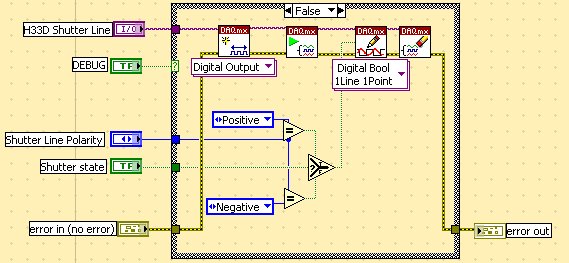
There is almost everything using examples > find examples... menu
but here is one which simply sends a single impulse:
Note that I expect the line have been pre-defined in MAX (it's always a good idea to check that your DIO line behaves as expected by trying it in MAX).
-
How to generate a variable frequency pulse train constantly
Hi all
I am using NOR-USB-6259 (BNC) to send signals of impulse to the position of a servo with labview motor control. The position of the servo-motor control follows these rules:
- The pulse train number determines how many degrees the motor;(par exemple la position angulaire dele de moteur)
- The pulse frequency determines how fast the engine is running; (for example the engine rotation speed)
- Digital determines the direction of rotation of the engine (for example in the clockwise or counterclockwise)
My question is when I have to continuously generate a body finished, train signal in a period of time. Here's a sample:
Time (s)
Number of pulses
Direction of rotation
(1 clockwise, counterclockwise 0)
Frequency
0-1
923
1
923hz
1-2
3540
0
3540hz
2-3
1751
1
1751hz
3-4
2663
0
2663hz
4-5
353
0
353hz
5-6
1017
1
1017hz
6-7
3436
1
3436hz
7-8
10 p
0
302hz
8-9
1513
1
1513hz
9-10
570
1
570hz
Here is the explanation of this table, the motor continues to turn clockwise for 0 ~ 1s. When the time reaches 1 s, the engine simply fill out the rotation of 923 pulse signals. And then the engine starts to turn clockwise for 1 sec ~ 2 s. When the time reaches 2 s, the engine simply fill out the rotation of 3540 pulse signals. So we can see that the speed of rotation of the motor to 0 ~ 1 s is different from the speed in 1 ~ 2 s. Namely, the frequency of the signal from pulse to 0 ~ 1 s is different from the frequency in 1 ~ 2 s.
I already use the DAQmx counter output, it can simply generate pulse signal with some numbers and some frequency only once. The attachment is the vi that allows to generate a digital pulse train finished the meter output channel and frequency, cyclical, delay report Initial and idle state are all configurable.
How can I continuously generate a series of pulse train with a variable number and frequency for a certain period of time.
Thank you very much for your help!
The frequency 'on the fly' control requires intervention of software and can not guarantee a specific number of impulses for each rate (which I assume you want because it's an engine step by step).
If it was me I would do one of them instead:
1. use the digital output for everything. The digital output at a higher clock rate and build the waveform to give you the desired number of steps and management. This method would give less temporal resolution than others.
2. use a task of meter output, 1 section at a time. Reconfigure and restart the task for each section after the management output setting. This method could introduce a delay between each section.
3. purchase of new equipment - X series supports put buffered outputs of meter that can do what you ask.
Best regards
-
How can I specify a delay generates a pulse meter?
Hi all
I have a question on the use of the meter to generate the pulse train. I did not how to program but I try the test panel in MAX and I see that it generates pulse train to certain rates and with a pulse duration. I think if it is possible to generate only a single pulse with given the duration of the impulse to sometimes after I start the job? I have a code to generate an analogue waveform, waveform of 35ms. I wonder if it is possible to synchronize the output of the analog waveform and counter such to 12.5ms after that the output waveform has started, I send this unique pulse from the meter port on. I have no idea how to do that, I think to use a delay but it is difficult to accurately control the time exactly 12.5ms.
Well, assuming DAQmx_Val_Low for the resting State, fires the meter will wait the initial delay and then generate a pulse at the time you request. Little time is not actually used in this example simple impulse.
From what you described, you must add a trigger to start your task of meter output (DAQmxCfgDigEdgeStartTrig) to you can set the meter to trigger off the beginning of analog output trigger. Set the initial delay on the counter for 12.5 ms. Start the task of counter in front of the task of the analog output. You should get your pulse 12.5 ms after you have started the task of the AO.
Best regards
-
How can I generate modulated amplitude signal?
How can I generate modulated amplitude signal?
I got this VI examples NOR but in this VI "m message signal .vi is missing. So, how can I generate missing VI or VI full for the Amplitude modulation signal using 5441 PXI and PXI-5610 as upconvertor. If possible guide me steps to generate.
Thank you and best regards
Isabelle Kodgirwar
Graduate student
University of Texas at Arlington.
Hi Aron,
-
How to generate pulses on the digital i/o lines? USB-6211 labview 8.5
I want to generate a 5ms pulse on one of the lines of digital output that will be more used to delay the acquisition, DAQ.
Thank you
You will need to use counters to generate a digital pulse. I ask you to take a look in the examples that come with the DAQmx driver (in LabVIEW, help goto-> find examples). You can look for impulses and select generate Dig Pulse.vi. If you have questions, after return!
-
How to use multiple digital channels on a 9474 when generating a pulse on a 9172 train?
I use a 9172 with 9474 module to the location 6. I want to generate the PWM signal 1 but, I have to be able to provide up to 4 amps. I have a solution but, I'm not sure it's the best way to do it. I'm basically starting and stopping the task and change PIN output in my startup routine. DAQmx does not disconnect the old pine when he signs so new, I'm able to run 1 signal via the 4 outputs.
   /*********************************************/   // DAQmx Configure Code   /*********************************************/   DAQmxErrChk (DAQmxCreateTask("",&taskHandle));    DAQmxErrChk (DAQmxCreateCOPulseChanFreq(taskHandle,"cDAQ1Mod6/ctr0","",DAQmx_Val_Hz,DAQmx_Val_Low,0.0,1.00,0.50));    DAQmxErrChk (DAQmxCfgImplicitTiming(taskHandle,DAQmx_Val_ContSamps,1000));    DAQmxErrChk (DAQmxRegisterDoneEvent(taskHandle,0,DoneCallback,NULL));

   /*********************************************/   // DAQmx Start Code   /*********************************************/   DAQmxErrChk (DAQmxSetCOPulseTerm(taskHandle, "cDAQ1Mod6/ctr0", "PFI0"));  DAQmxErrChk (DAQmxStartTask(taskHandle)); DAQmxStopTask(taskHandle);    DAQmxErrChk (DAQmxSetCOPulseTerm(taskHandle, "cDAQ1Mod6/ctr0", "PFI1"));  DAQmxErrChk (DAQmxStartTask(taskHandle)); DAQmxStopTask(taskHandle);    DAQmxErrChk (DAQmxSetCOPulseTerm(taskHandle, "cDAQ1Mod6/ctr0", "PFI2"));  DAQmxErrChk (DAQmxStartTask(taskHandle)); DAQmxStopTask(taskHandle);    DAQmxErrChk (DAQmxSetCOPulseTerm(taskHandle, "cDAQ1Mod6/ctr0", "PFI3"));  DAQmxErrChk (DAQmxStartTask(taskHandle));
What is the best way to do that with my current hardware? Also, I got to spend the 4 amp uses this method?
Thank you
P.C.
Hi P.C.,.
DAQmxSetCOPulseTerm() only accepts one signal, but DAQmxExportSignal() accept multiple signals, so here's a simpler way to do the routing:
DAQmxErrChk (DAQmxExportSignal (taskHandle, DAQmx_Val_CounterOutputEvent, "/ cDAQ1Mod6 / PFI0:3")); "))
DAQmxErrChk (DAQmxStartTask (taskHandle));
Brad
-
How to generate an impulse to test short circuit in an inducer
Hello
IM new to labview and am in need of complete SURG - SURGE STRESS TEST
This test is intended to detect a short tour inter by applying a number of high
voltage pulses (or surge) for the selected winding.
Each pulse should produce one sinusoidal transient that eventually decreases to zero.How to generate the impulse using labview.
Hi Jessica,.
Please see the "pulse pattern.vi" function--> pallets of signal processing signal generation.
Otherwise, you can browse through examples of LabVIEW.
Kind regards
Srikrishna.J
-
generate a digital signal for 6722 or 6221
Hello
Thanks first for the help I'm already on this forum.
Now, I have the following problem:
I like to generate a digital signal: high for 300µs, low 300 µs, 300µs high, low 300µs, top for about 2 ms.
I'm looking for a solution how to generate this numerical sequence. At the same time, I will read the information via an analog input (if all goes well, I now have a solution for this problem).
I tried to find examples, but I failed. For the moment, I was not able to produce any numeric sequence that worked.
My hardware is 6722 or 6221 - which should be OK with respect to the calendar.
Thank you
-
How to generate arbitrary waveforms FRO meter
Hello
I have a problem in the generation of the wave as shown in JPG below. Need to generate digital waveforms 2
1. with the help of counter0 - digital waveform will be with pulse 60 (58 - good pulsations and 2 empty pulse)
2. with the help of Freqout - digital waveforms should be to synchronize with a 40 pulse signal 2 signal should be high for then 5 impulses.
I tried model digital generation with Boolean 2D table convert to digital waveforms. But somehow, I couldn't have expected waveform.
If someone could help me in this problem.
Thanks in advance
Vijay
FREQ Out is not able to generate either of two waveforms - it can only generate continuous pulse trains. In fact, even one of the complete M-series meters would be unable to generate your "Signal 1" - you must use the 2nd meter to the signal from the door.
Supported boards of series X buffered output of the counter and could therefore be used to generate a waveform. You can use Freq Out yet, but the X series boards have also 4 full meters if this should be enough resources such as Freq Out is not necessary.
Best regards
Maybe you are looking for
-
Someone has charged my account for its Apple's music subscription
I received an e-mail from Apple TM Inv. It's a bill of subscription of Apple's music for someone else. I do not agree to the Apple's music. Could someone advise me please on what to do?
-
my macbook pro doesn't turn on. It makes a noise and the light turns on but then turns off. Nothing on the screen. Can anyone help?
-
I designed a data logger USB that collect data in real-time. These data are read via PC usb host port. The data collection is very slow and sometimes it can take between 5 to 10 seconds. If the data is not ready the device continue to send NAK to the
-
search function is missing the .wpd file type
When I do a word search it is more discpays Word Perfect files that contain the word I'm looking for
-
Why my screen saver settings are grayed out
On one user on my PC, I am unable to change the screen saver activation time of 10 minutes. The box 'on CV.... ' is also unavailable. Under XP it was only grayed out when the screen saver says 'None '. As soon as you have selected something, then y