How to trace the temperature and voltage using the graph of Mixed Signal
Hello
I use the NOR cDAQ-9178, module NI 9214 (temperature) and the module NI 9201 (voltage). My program allows the user to choose among 3 different tasks, Masurement of temperature, voltage, or both. When you select the task for temperature and voltage measurement, I was drawing all channels on the same graph. I was invited to separate channels of temperature and voltage and draw on a split graph, using the same category axis. I tried stacking, but could not control where each parcel channel went. I think the Mixed Signal graph would work well. Everything works and records all the data of the channels to the files, but my plots appear not on the graph, although I can see the change in scale numbers. I think I can use the cluster incorrectly. Can someone tell me what I am doing wrong? I selected the 'Plot Visible' option, but the plot is not always displayed. I've attached a zip with all the screws needed to run my program. The main VI is "Voltage_Temperature_SingleTask_Measurements_MAIN.vi"... but everything must be downloaded to the program works. Please help... Thank you.
Hi mzhlb,
I complained only the expressVIs.
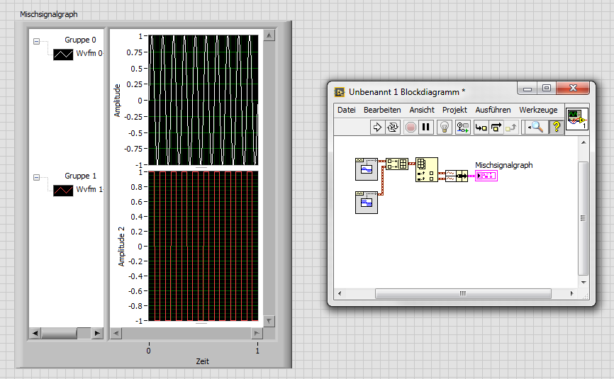
Why not use simple IndexArray function to get bots waveforms of your waveform table? (I faked it your DAQmxRead with functions SigGen).
Tags: NI Software
Similar Questions
-
How to reset the graph of mixed signals automatically?
How do you resets a graph of mixed signals automatically?
My idea is like that - I'm drawing a chart throughout the day... Then, at 19:00, I want the chart to erase. There will be a break until 06:00. It will therefore start a new graph at 06:00. How can I do this? It seems easy, but I can't find the solution. Thanks in advance!
redhotsneakers wrote:
Why local variables are useless?

It's a missquote, I'm afraid: I didn't say local variables are unnecessary, even if some would align themselves with this statement. I said that they are in your case. In VI you have published everything first, you are passing data from local variable that can be better spent by wire sind, the variables are literally next to each other. While you might get lucky in a program of this size, it can cause a world of problems in a larger application.
Back to your problem: after watching your new VI, I'd say you're almost there. Separate features in the two loops does not seem necessary. Instead of the value property, you can try the method reinitialize I mentioned earlier, that should do it.
Then you can add a feature that reinitilizes only once by comparing the range in the previous iteration.
BTW: this select function is code of rube goldberg. Why not use the Boolean result of the node equal to the cases.
-
How is - I size the Group zone oin the graph of mixed signals to meet my signal names?
I have a graph simple signal mixed and I programmed my signal names and they are longer than the width of the component group existing on the subject, and I want them to be visible. How can I resize the graphic components because I wrote the names to the object? I know that I can personalize the thing, but y at - it a method or a property that I'm missing here?
It seems that it is a known problem. You can change the size of the legend by using a property node for waveform graphs, but not for a graph of mixed signals. A good work-around would be to right-click the gray bar between the legend and the plot area until your pointer changes to the resize tool. You can then size it is large enough to show the whole legend. It is a question that is configured to be resolved in future versions of LabVIEW.
-
How to draw the graph of output?
Hello
How to draw the graph of an exit? is there any api for it?
The short answer is that there is no API, but you can create your own field if you want to, and here are some samples:
http://supportforums.BlackBerry.com/T5/Java-development/create-graph-fields/Ta-p/444968
I recommend the search before you ask questions to see if other people have asked similar questions. If you type chart in the search box you will find other similar topics.
-
How to dynamically add a plot to a graph of mixed signals
I have a graph of mixed signals where I'm plotting a signal from a time axis. I'm trying to dynamically add a second plot to this graph against the same time axis (with a different scale of Y), but when I built a 2D array and try to connect in the graph (using a local variable) I get an error of size mismatch. I know for sure I did in the past (cable tables with different sizes for a same MSG) with no problems but, today, for some reason any I can't solve this problem.
Am I missing something?
Yes, you're probably writing a table 1 d somewhere that is causing to accept only 1 d. To address your problem above, just put a table node build in whenever you have a 1 d table and it will be just a 2D array with a single line of data.
To add a field to your current locations, your screenshot above should work once the plot knows that he has to accept the 2D tables.
Reading from a local variable, change something and then write about it once again can lead to a lot of issues down the line. Race conditions are a pain in the butt, so get rid of that sort of thing is good to do from the start. I didn't know the rest of your code, so I don't know how you treat it, but just keep in mind that you add to your software.
-
Measure the current and voltage using DMM sharing a port
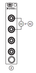
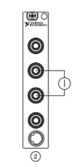
I want to measure pressure several times on a pcb, where I connect the ports of digital multimeters to the card using simple cards. Switching between the different voltages is done using simple. If the black port of DMM (the second from the top photo) is connected to the Earth to give the measure correct volt.
And then I want to measure current through different lines. The problem is here. Given that two measurement types share a port, how do I get the correct voltage and current measurement? The second port of top would be grounded, so I can't use the method of measuring the voltage across the line through a resistance with a known value, since then the second port must not be connected to the ground. How can I use the current state of the DMM measurement? How measure current? Are there examples of this? Tried looking through manuals, but could not find the good starting points.
so I can't use the method of measuring the voltage across the line through a resistance with a known value, since then the second port must not be connected to the ground.
On all of my games to test I have to mux my land of the signal along with the salvation of my signals.
All my mux test sets are set up for the topology 2-wire because there is no other way to do it without the weak side of switch also.
-
How to trace the signal acquired against the clock all the time fixed by using Graph XY?
Hello
My goal is to trace the signal acquired against the clock all the fixed time dynamically. In General, it is like trace the waveform of the signal against the clock in a graph, but don't keep the recent 10 min waveform. My current approach is to get the timestamp by a VI and the express VI to use XY graph to make the plot. The result keep all data in the history which is not what I want. My question is that how to achieve my goal?
Thank you very much
Hao
One way to show the last ten minutes of data is to use a graphic instead of a graph. Set the size of the history of the ranking for the number of samples you acquire in ten minutes.
If you want to use the graph XY, you will need to manipulate the data yourself. If you don't want data from the last ten minutes and you want to throw all the old data, set up a circular buffer sized to hold the ten minutes of data. Once the buffer is full (after the initial ten minute break) adding a data point removes the oldest point. Make the buffer of a 2D with X data table in a line and the data Y in the next line. A queue with loss can be used in recent versions of LV to implement a circular buffer. In older versions, a driving force would be a good choice.
Lynn
-
Hello world. I need to trace the variable amplitudes compared to the timestamp (date and time), but the time intervals between samples are not equidistant. In my area, this is called trend plot. I'm surprised that Labview does not a vi to do this. The only solution that I found so far is to save the data in an Excel file and open this chart in Excel because it has the ability to trace what that this is against what whatsoever is not limited to something as even spaced samples. How to achieve this is Labview? A graph of waveform vi would be perfect if it was not by the fact that it works with even spaced samples.
Thank you.
Paulo Siqueira
Your requirement is directly possible with LabVIEW.
You can spend time to understand the difference between 'Chart', 'Graph' and "Graph XY".
VI attached is drawing samples of unequal time.
Hint:-right click on the 'XY' graph-> properties-> display-> 'Axis of X' = absolute time Format
Kind regards
Yogesh Redemptor
-
How to trace the path of a motion tween?
Is it possible to trace the path takes a symbol and create a (or the forms that appear as a tracing)?
Example very Simple: the letter C, without serifs. Basically a bow.
I would like to than the C to 'pull' in the animation. I just hope interpolation along the C of movement and trace its path. I did a shape tween and wasn't happy with the results. In addition, complex paths would be very difficult to shape tween.
Thank you!
This is best done with ease using Adobe After Effects using an edge effect and animation which. You can then import the output MOV in Flash Pro for the purpose of interactivity. Otherwise it would be better done by drawing manually track with the mouse or tablet in Flash directly, rather than a script, even if you can exist if anyone knows.
-
How to trace the constant width - bar graph?
Hi all?? I'm having a problem...
I have two tables 1 d, I have them plotted using Graph XY with bar graph, the problem is that I'm not able to get the bar with consant width chart.
How to get the bar with a constant width...
Could just be it please one through little light for my querie?
I enclose my VI, façade, block diagram
Thanks in advance...
Hi girikavali,
you could do shows in order to create a Subvi which automatically adds these points of NaN?
-
How to add the graph that appears on the left of the URL in the title bar?
The graph of M prior to the Inbox.

Hi LAP-DAD,.
This is probably a so-called Favicon you can create in Photoshop or any other decent graphics program.
Favicons are 16px x 16px or 32px x 32px size images and they usually have the .ico file.More information on Wikipedia: Favicon - Wikipedia, the free encyclopedia
Kind regards
MauriceThis answer was helpful? Please consider marking it as 'Useful' or 'Right answer' (as appropriate) to help future customers with the same problem. Thank you!
-
How to get the graph to print in color when added by script
Hi all
I'm trying to add an image to an article through dal, but it does not print in color when it is added using script. But if manually added it prints in color.
Do I need to have any setting for this. Please let me know.
Thank you.
I'm not 100% sure that this will work, but you can try adding an empty bitmap in Studio to your section, make sure that it is marked as color printing. And then use script DAL CHANGELOGO function to change the bitmap that you want to print. So, indeed, you replace ADDLOGO by CHANGELOGO in DAL and create a bitmap on in the Studio.
-
absolute time in the chart of mixed signals
I am trying to build a chart of mixed signals with 4 inputs (Temp, Temp setpoint, % RH and set RH %). I want the X axis to be absolute time, but do not know how to wire properly. To search the help files and discussion forums, I think I should include a timestamp as a DBL. So far, I have created 3 scenarios:
- All of the lines of work but x 4 entered is relative.
- Two main lines of work and entered x is absolute time (below)
- Even with 4 inputs graphic breeze with an error that the number of entries in cluster does not match (away). ???
I seem to be missing something basic. I would be very happy to anyone help... until the computer gets!

PS LV8.5/WinXP Pro


There seems to be a problem with the time of the x axis when you enter analog data tables and the waveform of digital data. Try the attached vi where you are piping the analog data as waveforms. Allows always to look at the data as it is collected over a period of time, which is what it seems you are trying to do. It also has a clear function. My example is rough; It would probably be best done with loops producer-consumer or one event loop to make it more effective. Let me know if this does not work.
-
How to trace the number and string in a line (meter data via MODBUS recorder)?
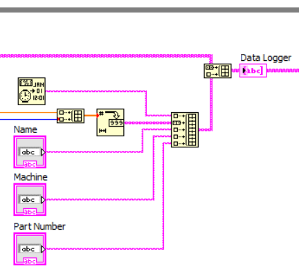
Hi all I did the log data amount using digital via modbus (RS485) meter to monitor how much and to reject what has and name operator, Machine and the part number.
I have problem on plot number & string in one line, as shown in the image below:

How to move this channel on a line? I enclose my vi.
Thank you ~.
Hi rhiesnand,
at the moment you add 2 new lines in your table.
The solution is to concatenate the two parts of the line to a greater range of 1 d before adding this table as a new row to your table 2D!
Like this:
-
How clone a HARD drive and then use the clone with VMware (as well as Windows works!)?
I have a system where Windows 7 is installed, and I'm doing a clone of her image of HARD drive, I then want to use in my main with VMware PC, so that I can start Windows 7 at the cloned disk.
I used Ultimate Boot CD v5.1.1 with which HDD I wanted to clone, and I cloned using EaseUs Disk Copy, which comes with Ultimate Boot CD. The source HARD drive was 250 GB in size which had 3 partitions, while the USB HDD I have attached to the system, which was supposed to be the disk of destination/clone, was 320 GB in size. I chose to create a replica, exact and up to 250 GB of data (partitions, etc.) has been copied exactly, and the rest of space was not allocated. I have now connected this USB HDD to my main PC, shot to the top of VMware Workstation 8 and defined a new Virtual Machine and chose to boot from the USB HDD.
The result is that when Windows starts (from the cloned HDD inside VMware), I get the blue screen error until I get to the login screen.
How can I change my methodology so that Windows starts even on the clone? I can change the tools I use, etc.
You can use the usb drive is
you only need to patch the system a little registry
to do this, you start the virtual machine with the usb drive in a restore win7 CD, and then follow the instructions I posted here
http://sanbarrow.com/p2v2008r2.htmlPatching - easy Variant
This procedure is used when otherwise the VM would start in a kind of bluescreen 7B.
This means that VMware is the target and that you configure the computer virtual with VirtualHardware type 7.
It applies only if the virtual disk is configured like this
scsi0.virtualDev = "lsisas1068".
scsi0:0. FileName = "imported.vmdk".On the platform target start the virtual machine, newly created in the Windows 7 recovery CD.
After the initialization is complete, click CMD and run regedit.
Select HKLM, then Menu > file > load hive.
Navigate to the Windows directory on the virtualdisk > system32\config and select the file SYSTEM.
When asked for a name enter p2v.
Then find the keyHKLM\p2v\ControlSet001\services\LSI_SAS
and the startup type of the REG_DWORD value 0
Select HKLM\p2v, and then click Menu > file > unload hive.
You can now close regedit and restart.
The next time you start, you can start in the 2008 R2 system. He should find the drivers and probably need to reboot when finished.


Maybe you are looking for
-
Camileo H20 - strange noise throughout the video
Hello. I today received delivery of my first camcorder, which as the title suggests, is a Toshiba Camileo H20. Overall, I am impressed with this little camera, but there is a problem that concerns me. After reviewing a video of test, I created to see
-
the variant attribute value - how fast it is?
Hello There were days OR presentation on attributes of type variant. There are example saying that variant can be used to remove duplicates from table 1 d and this supposed to be a very quick solution. I did some tests and it seems that is not: On th
-
How to view files (photos) I clicked on hide in picasa
I wanted to hide some photos in picasa duplicate, but all disappeared and I can't have their backs .can someone help me
-
Must configure WAG54GS as static IP of no. - NAT router
I have a WAG54GS and I also have a Linksys firewall device, separate units. My PC are behind the Linksys firewall that has a port WAN1 allowing plug a router device. Currently the WAG54GS is factory with NAT and active firewall settings. I want to us
-
I'm upgrading from my memory and wonder what I can use...
Setup: HP Pavilion p7 - 1370 t. Windows 7 Motherboard of Carmel (single channel architecture) I want to upgrade to 8 GB but cannot pick up a good set of 2 x 4 GB and edge... at the same time I was wondering the performance of memory dual channel sing