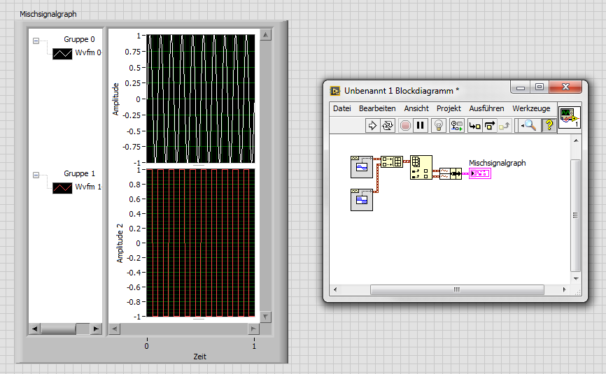
How is - I size the Group zone oin the graph of mixed signals to meet my signal names?
I have a graph simple signal mixed and I programmed my signal names and they are longer than the width of the component group existing on the subject, and I want them to be visible. How can I resize the graphic components because I wrote the names to the object? I know that I can personalize the thing, but y at - it a method or a property that I'm missing here?
It seems that it is a known problem. You can change the size of the legend by using a property node for waveform graphs, but not for a graph of mixed signals. A good work-around would be to right-click the gray bar between the legend and the plot area until your pointer changes to the resize tool. You can then size it is large enough to show the whole legend. It is a question that is configured to be resolved in future versions of LabVIEW.
Tags: NI Software
Similar Questions
-
How to reset the graph of mixed signals automatically?
How do you resets a graph of mixed signals automatically?
My idea is like that - I'm drawing a chart throughout the day... Then, at 19:00, I want the chart to erase. There will be a break until 06:00. It will therefore start a new graph at 06:00. How can I do this? It seems easy, but I can't find the solution. Thanks in advance!
redhotsneakers wrote:
Why local variables are useless?

It's a missquote, I'm afraid: I didn't say local variables are unnecessary, even if some would align themselves with this statement. I said that they are in your case. In VI you have published everything first, you are passing data from local variable that can be better spent by wire sind, the variables are literally next to each other. While you might get lucky in a program of this size, it can cause a world of problems in a larger application.
Back to your problem: after watching your new VI, I'd say you're almost there. Separate features in the two loops does not seem necessary. Instead of the value property, you can try the method reinitialize I mentioned earlier, that should do it.
Then you can add a feature that reinitilizes only once by comparing the range in the previous iteration.
BTW: this select function is code of rube goldberg. Why not use the Boolean result of the node equal to the cases.
-
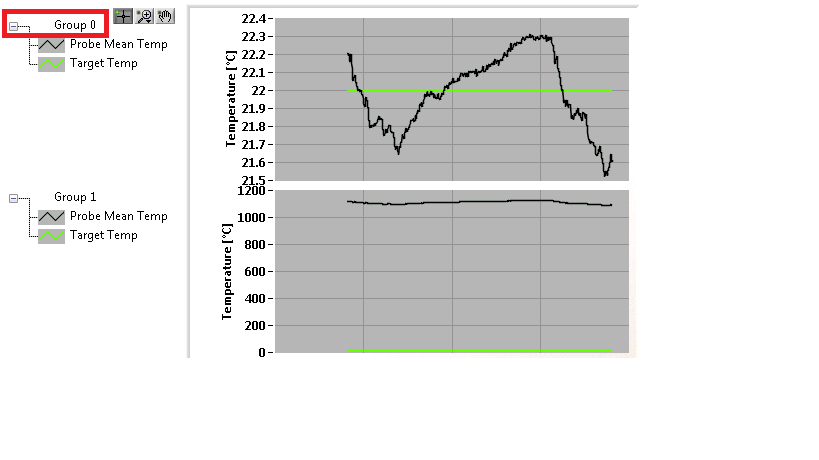
How to trace the temperature and voltage using the graph of Mixed Signal
Hello
I use the NOR cDAQ-9178, module NI 9214 (temperature) and the module NI 9201 (voltage). My program allows the user to choose among 3 different tasks, Masurement of temperature, voltage, or both. When you select the task for temperature and voltage measurement, I was drawing all channels on the same graph. I was invited to separate channels of temperature and voltage and draw on a split graph, using the same category axis. I tried stacking, but could not control where each parcel channel went. I think the Mixed Signal graph would work well. Everything works and records all the data of the channels to the files, but my plots appear not on the graph, although I can see the change in scale numbers. I think I can use the cluster incorrectly. Can someone tell me what I am doing wrong? I selected the 'Plot Visible' option, but the plot is not always displayed. I've attached a zip with all the screws needed to run my program. The main VI is "Voltage_Temperature_SingleTask_Measurements_MAIN.vi"... but everything must be downloaded to the program works. Please help... Thank you.

Hi mzhlb,
I complained only the expressVIs.
Why not use simple IndexArray function to get bots waveforms of your waveform table? (I faked it your DAQmxRead with functions SigGen).
-
How to re size the canvas? (I'm not asking the jury of art, but the canvas)
How to re size the canvas? (I'm not asking the jury of art, but the canvas)
The Web cannot be resized.
-
How to dynamically add a plot to a graph of mixed signals
I have a graph of mixed signals where I'm plotting a signal from a time axis. I'm trying to dynamically add a second plot to this graph against the same time axis (with a different scale of Y), but when I built a 2D array and try to connect in the graph (using a local variable) I get an error of size mismatch. I know for sure I did in the past (cable tables with different sizes for a same MSG) with no problems but, today, for some reason any I can't solve this problem.
Am I missing something?
Yes, you're probably writing a table 1 d somewhere that is causing to accept only 1 d. To address your problem above, just put a table node build in whenever you have a 1 d table and it will be just a 2D array with a single line of data.
To add a field to your current locations, your screenshot above should work once the plot knows that he has to accept the 2D tables.
Reading from a local variable, change something and then write about it once again can lead to a lot of issues down the line. Race conditions are a pain in the butt, so get rid of that sort of thing is good to do from the start. I didn't know the rest of your code, so I don't know how you treat it, but just keep in mind that you add to your software.
-
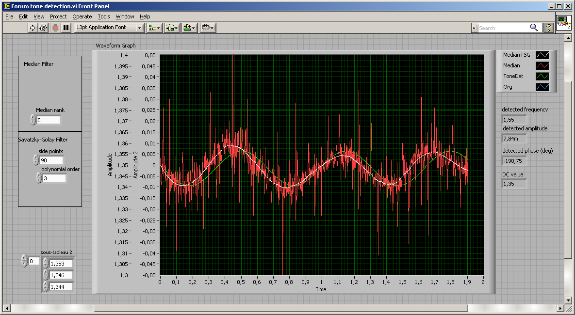
How can I remove the noise of a signal?
Hello world
I need to extract the phase of a signal of 1.5 Hz which has little noise (see attachment files) and MAX I was recording the signal to 500 Hz. I use the filter of Labview tool value 'smoothing' with a factor equal to 3. Could someone tell me if using the right tool for what I want to do? If so, is-3 a correct number of retativaly? Looking at the result of the signal is much better.
Thank you
User
here still to play

I did not use the ordinary filter, but also more you know about the original signal, the better your filter or fitting can be.
If you know it should be a sinus (maybe even with a constant frequency) and you want the phase, go with detection of tone or a linear adjustment...
the median filter is good against the spikes, the filter of SG will make an adjustment of polynomial (original designed for adjustment of Spectra but it's also nice noise with propper settings)
Uups, the pic was taken without median filter...
If you tell us more about the signal, we could offer best filter. And keep in mind that most of the filters have an influence on the phase of the signal (late phase/group).
-
How to ensure that the graph xy plots are present?
Hello community,
Since the update to LabVIEW 2014 this week, I have a problem with the code that worked (or didn't, but the problem was unnoticable).
As example the llb I created to present the question, I'm graphic xy filling with quiete some data and then color programmatically plots.
The problem is that if there are too many plots then the property nodes that are to color the mistakes of Mr. thow plots as if the corresponding plots were not present in the graph still - even if I used a single flat sequence structure to try to ensure that the data is written in the plot before trying their color.
Maybe this wouldn't be in LabVIEW 2013 too - but the threshold for the number of plots was higher. All I can say is that I have observed this with data sets that worked well in 2013 of LabVIEW.
To reproduce simply run 'color of the graphs.vi' with values high enough to 'numerisch' and ' numerisch 2 "(50 on my machine can be more about yours).» I left the terminal nodes property unwired error so you get caught up in the right position when the error occurs.

Somehow check if all parcels are in the charts again? This way I could introduce a delay that ensures that I don't have the color of the graphics that do not exist yet - regardless of the speed of the target computer.
Xy graph behavior has changed in 2014 of LabVIEW? Or maybe his performance?
Best regards
Florian
HM, your addendum somehow answered my question. We are indeed an against the user interface thread race condition.
Unfortunately, I do not know a method to wait than the UI thread to have access to all plots. In addition, the waiting time that you need depends on the ability of the system, which is dynamic, you know not all processes background or in parallel, running applications.
That being said, I recommend a work around:
1. create the data for the plots
2. how many plots you have in query data
3 write short dummy data in the terminal, and not the data of the whole plot
4 Recolor plots
5. write the correct field data
Norbert
-
How can I measure the voltage of a signal?
Well!
I'm trying to read the voltage of a signal using acquisition data PCI-6229 card.i am giving the signal as an input to the DAQ card and try to read the voltage level. The range of my signal is 4.8 ~ 5.5 VDC but the results are not accurate, such as measured with DMM. My code is as follows:
1.i m using DAQmx create channel to create an analog input channel
2. then a sample clock with finite samples, sampels by channel and set the rate of iteratively
3. then I start the task
4. analog playback 1 DBL AK1 N sample d
Pressure readings I am differs widely that the actual.e.g a signal measured with DMM is 5v but when applied to the DAQ hardware and measured gives 6v.also I have to define minimum values and maximum in VI... If I put 4 to 5 maximum and minimum to measure a 5vDC signal it gives good result. , but if I change the maximum setting to 6v then it gives me results.also bad behavior is different for different signals for example when I measure a 6.5 VDC to signal that it shows me the voltage as 7.3V...
Photo of my code of VI is attached... Please answer... or give me another code that works fine at the voltage of a signal reading.
-
absolute time in the chart of mixed signals
I am trying to build a chart of mixed signals with 4 inputs (Temp, Temp setpoint, % RH and set RH %). I want the X axis to be absolute time, but do not know how to wire properly. To search the help files and discussion forums, I think I should include a timestamp as a DBL. So far, I have created 3 scenarios:
- All of the lines of work but x 4 entered is relative.
- Two main lines of work and entered x is absolute time (below)
- Even with 4 inputs graphic breeze with an error that the number of entries in cluster does not match (away). ???
I seem to be missing something basic. I would be very happy to anyone help... until the computer gets!

PS LV8.5/WinXP Pro


There seems to be a problem with the time of the x axis when you enter analog data tables and the waveform of digital data. Try the attached vi where you are piping the analog data as waveforms. Allows always to look at the data as it is collected over a period of time, which is what it seems you are trying to do. It also has a clear function. My example is rough; It would probably be best done with loops producer-consumer or one event loop to make it more effective. Let me know if this does not work.
-
How to automatically size the images at screen resolution?
Hello
I need a little help, automatically reducing image resolution of viewers.
I did it with a table and it works fine:
< table width = "100%" border = "0" >
< b >
< td align = "center" bgcolor = "#66CCFF" > < h1 style = "do-size: 30px;" text-align: center; "> < em > Table Title < /em > < / h1 > < table >
< /tr >
< /table >
But I have no idea how do to the image.
When I use the normal display mode the picture looks fine, but when I go into mobile view it sticks out of the page, while the table has a proper resolution.
How can I fix it?
Do not use table layouts. They are completely ill-suited to modern web design and in particular, responsive web design.
Use CSS layouts with widths of division in %.
Example:
CSS code:
Body {width: 100% ;}}
IMG {max-width: 100 %}}
HTML code:
http://placehold.it/500x350">
Preview in browser & resize your window to see what is happening in the image.
Nancy O.
-
Graph of Mixed Signal: how programmatically change the name of the group in the legend?
Hello LabVIEW community,
Can someone tell me the property node that would allow me to change the name of 'Group 0' programmatically in the legend below? I have searched through all mixed methods graphic Signal and nodes of property with no luck and should just be overlooking it.
Thanks for your time.
Steve
Hello Electromecha,
Unfortunately, there is not a property node associated with the name "Group" in the legend. Several others have made that suggestion over the years. I recommend kudoing the idea in the IdeaExchange.
-
How to automatically size the TextField?
Hai...
I'm trying to get a string of xml file each channel have different length... I need to adjust the height of the textfield automatically. Everyone knows the idea about this please help me.
Thank you
Dembélé
You can view the code? Have you tried using the autoSize property?
import flash.text.TextField;
import flash.text.TextFieldAutoSize;

var result:TextField = new TextField();
result.autoSize=TextFieldAutoSize.LEFT;
-
Script folder level? How can I use the value of a field as a pdf file name to save as dialog box
I read somewhere that if you use a script to the folder level, you can do things like save a PDF with a specific file name - possibly based on a domain name.
How we put in place a folder level script?
How to run a script from the PDF?
What code do you use to change the name of the PDF for the content of the text fFieldName field?
Or is - this really just impossible to do?
The function must be placed in a .js file in the following folder:
C:\Program Files (x 86) \Adobe\Acrobat 11.0\Acrobat\JavaScripts
You can then call it go another level of the folder or the document itself
script.
-
How can I filter the noise of a signal?
Hello
I wonder if someone can point me in the right direction.
I got the task to analyse the signal from a load cell, measuring vertical efforts on a buoy in the ocean waves. All I have are data files - Earth "calibration" run and a period of measurement of forces in the water. They are both simply traces time force vs. time. Calibration run consisted of hanging weight of the load cell. The problem is that the signal is very noisy, with a +/-10% fluctuation around the average. I don't see any particular model or the periodicity for the noise, but there may be something there.
As a mechanical engineer, I don't know a lot about the signal processing, but I think there may be techniques to characterize the noise and filter it essentially leave the signal of interest (buoy in the water). I tried to run Fast Fourier Transforms of the calibration and signals live (in MS Excel), but they gave me a huge spread of frequency component, some with puzzlingy large amplitudes. Can anyone suggest alternative approaches or indicate where I have gone wrong?
Thank you.
What are the software tools you have at your disposal to achieve this? Using LabVIEW? What is the sampling frequency of your signal?
The first thing to look for are the functions of filter and start by using a simple low pass filter (for example: Butterworth filter). In view of your signal, you expect the signal to be less than 1 Hz, so put 1 Hz as the crossover frequency. Who should get rid of a lot of noise already.
-
How to ensure that the graph of the image is registered before you add it to a report?
Hello!
I have a VI (comprehensive graphic image recording) that records the image of a graph with an invoke node.
Then, I set this image in an excel report. However sometimes the image is saved and sometimes not.
Usually, if I use a probe inside the VI it will save the image.
I thought that with the wire of the error I will force execution of saving image of chart first and then add it to the report but it seems that is not enough...
You have no idea why this is happening >
Thanks in advance!
Hi jess
As Global Variables are missing and no data is not able to run and find the root Cause. Always Modiifed the Code. Please run and confirm. I have Modiifed in LV 2015. If you have later please refer png File.
If his work during the probe. This may be due to timing issue with calling Vi
Kind regards
Master of potato
Maybe you are looking for
-
I have food on my Mac Pro Delta; I suspect it is bad. He has four caps, all the black wires. What pins should I check everywhere for voltage? Do whatever it is must be jumped to start it? Are there common fixes? Thank you
-
Why can't is to send text messages to non-Apple on my iPad Pro devices?
Is there a solution for iMessage in the works?
-
Incredible trouble with two A10 S203 network!
I had two Satellite A10-S203. This mobile are configured to operate on Microsoft network (wired network) with the working group. Have a different IP, name, MAC addresses, and same workgroup. To the network to work about 15 computers. When I connect t
-
Don't download apps on my iPad
It is not the usual case that plays to the App Store or whatever it is, it's more specific update/download problem. I mean a few months ago I clicked to update my applications (Facebook, Instagram, tumblr), so they changed to the little circle with t
-
Problem with TV show series purchased on iTunes
Bought 8 episodes of TV shows on the iTunes Store and they have downloaded in the Section TV shows to iTunes on my Mac. As it was a gift and I didn't not found immediately, I used the Options mode and temporarily transferred the episodes section of