absolute time in the chart of mixed signals
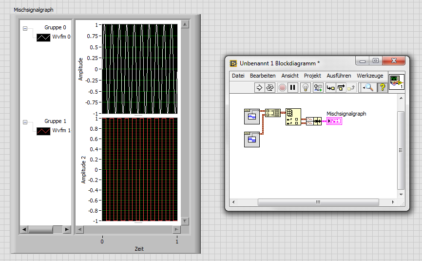
I am trying to build a chart of mixed signals with 4 inputs (Temp, Temp setpoint, % RH and set RH %). I want the X axis to be absolute time, but do not know how to wire properly. To search the help files and discussion forums, I think I should include a timestamp as a DBL. So far, I have created 3 scenarios:
- All of the lines of work but x 4 entered is relative.
- Two main lines of work and entered x is absolute time (below)
- Even with 4 inputs graphic breeze with an error that the number of entries in cluster does not match (away). ???
I seem to be missing something basic. I would be very happy to anyone help... until the computer gets!
PS LV8.5/WinXP Pro


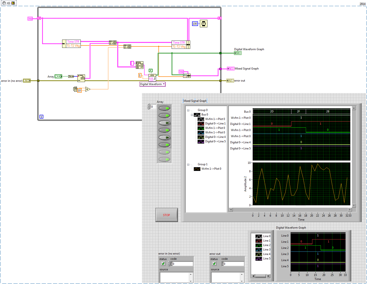
There seems to be a problem with the time of the x axis when you enter analog data tables and the waveform of digital data. Try the attached vi where you are piping the analog data as waveforms. Allows always to look at the data as it is collected over a period of time, which is what it seems you are trying to do. It also has a clear function. My example is rough; It would probably be best done with loops producer-consumer or one event loop to make it more effective. Let me know if this does not work.
Tags: NI Software
Similar Questions
-
Control chart and mixed signals tab crashed for LabView 2009
I find a serious problem by using the chart of mixed signals with tab control. Two examples and detailed drscription are attached. In TestMix.vi there is mixed, graphics and additional code to display the data. Normal execution of the program. I add the tab control and move the graph mixed signal in Page 2 (see TestMix2.vi). After registration as TestMix2, close the vi and oppening is façade of LabView frozen after touching on page 2 of the tab control.
Does anyone have the solution for this case?
Best regards!
In his stavljanjem digitalnog dijela na kraj grafa sam otkrio kao slucajnost, ali only Monte puku is tako I dolazi zaobilaznog rijesenja.
Kada dobije informaciju od kolega bi bug mogao biti rijesen obavijestiti cu spomenuti kada go! Moze biti u Drugom.mp3 od nadolazecih patchova ili u sljedecoj verziji LabView eventualno - a.
Srdacan pozdrav
Franjo Tonkovic
-
How to reset the graph of mixed signals automatically?
How do you resets a graph of mixed signals automatically?
My idea is like that - I'm drawing a chart throughout the day... Then, at 19:00, I want the chart to erase. There will be a break until 06:00. It will therefore start a new graph at 06:00. How can I do this? It seems easy, but I can't find the solution. Thanks in advance!
redhotsneakers wrote:
Why local variables are useless?

It's a missquote, I'm afraid: I didn't say local variables are unnecessary, even if some would align themselves with this statement. I said that they are in your case. In VI you have published everything first, you are passing data from local variable that can be better spent by wire sind, the variables are literally next to each other. While you might get lucky in a program of this size, it can cause a world of problems in a larger application.
Back to your problem: after watching your new VI, I'd say you're almost there. Separate features in the two loops does not seem necessary. Instead of the value property, you can try the method reinitialize I mentioned earlier, that should do it.
Then you can add a feature that reinitilizes only once by comparing the range in the previous iteration.
BTW: this select function is code of rube goldberg. Why not use the Boolean result of the node equal to the cases.
-
How to trace the temperature and voltage using the graph of Mixed Signal
Hello
I use the NOR cDAQ-9178, module NI 9214 (temperature) and the module NI 9201 (voltage). My program allows the user to choose among 3 different tasks, Masurement of temperature, voltage, or both. When you select the task for temperature and voltage measurement, I was drawing all channels on the same graph. I was invited to separate channels of temperature and voltage and draw on a split graph, using the same category axis. I tried stacking, but could not control where each parcel channel went. I think the Mixed Signal graph would work well. Everything works and records all the data of the channels to the files, but my plots appear not on the graph, although I can see the change in scale numbers. I think I can use the cluster incorrectly. Can someone tell me what I am doing wrong? I selected the 'Plot Visible' option, but the plot is not always displayed. I've attached a zip with all the screws needed to run my program. The main VI is "Voltage_Temperature_SingleTask_Measurements_MAIN.vi"... but everything must be downloaded to the program works. Please help... Thank you.

Hi mzhlb,
I complained only the expressVIs.
Why not use simple IndexArray function to get bots waveforms of your waveform table? (I faked it your DAQmxRead with functions SigGen).
-
How is - I size the Group zone oin the graph of mixed signals to meet my signal names?
I have a graph simple signal mixed and I programmed my signal names and they are longer than the width of the component group existing on the subject, and I want them to be visible. How can I resize the graphic components because I wrote the names to the object? I know that I can personalize the thing, but y at - it a method or a property that I'm missing here?
It seems that it is a known problem. You can change the size of the legend by using a property node for waveform graphs, but not for a graph of mixed signals. A good work-around would be to right-click the gray bar between the legend and the plot area until your pointer changes to the resize tool. You can then size it is large enough to show the whole legend. It is a question that is configured to be resolved in future versions of LabVIEW.
-
Mixed signal graph - data digital unable to see on the graph
Hello
I'm tracing analog and digital data on the graph of mixed signals. I'm not able to see numbers on the graph, but when I export data to excel it shows all digital plots also. According to me, Miss me some settings.
Please check attached VI for reference and let me know if anyone knows the solution
Kind regards
Jaysha
I changed the frequency of sampling to '1 '.
-
Problem with the display of the current time on a chart
Hello
I am strugglering with my software to make it work correcly.
I just got a problem left: I'm programming a software to record the temperature by thermocouples. The thing is, I used a property node to display my current chart... So far, no problem. But when I press a button that record the temperature, I pass in the case following my case structure where the graph is represented by a local variable, and then time dispalyed by the table isn't present anymore. Ideally, shoud graph display the current time at any time on the chart.
I don't know if my explanation is clear, so you can find my program as an attachment.
Any help would be appreciated, I'm desperate.
Thank you very much
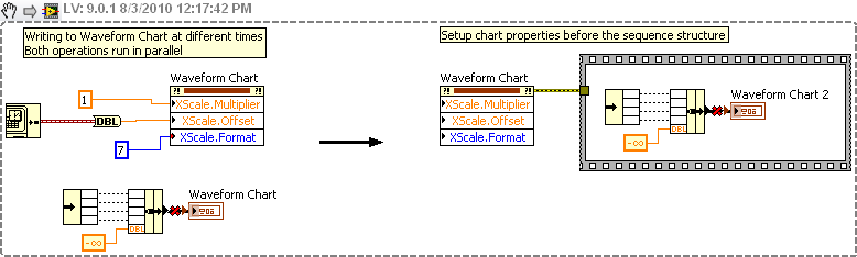
You write to a property node graphic of waveform at the same time to write data in the chart. You must write to the node property before writing data, the following diagram shows a path on the left and a better way on the right:
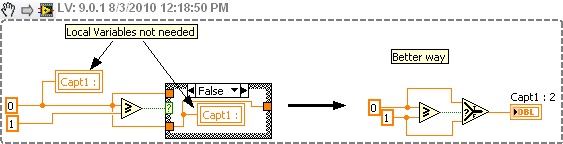
Here is another problem. You don't need all these variables. You don't even have the structure of the case:
One last thing. Equip your loops to avoid using time CPU 100% small delays, Wait (ms).
-
Get the absolute time on a chassis ethercat 9144 in labview fpga
I'm testing the timing and synchronization of a distributed system, consisting of an OR-cRIO-9082 and two ethercat NI 9144 chassis. Is it possible to access the system on the 9144 absolute time of in the FPGA?
Thanks for the reply. In fact, I just figured this out a few moments ago. It is possible to add a timestamp to a variable that is defined for the user by selecting 'Enable Timestamping' on the user defined variables properties dialog box. This timestamp does what I want, because it uses the absolute time of the 9144 (that is synchronized with the master clock), and this time can be read on the host/Master.
At least I think it does what I want. I'm in the process of coding and testing right now.
-
Programmatically formatting graphic mixed signals
I am writing an FPGA application where I am acquiring data from a unit under test (USE). The PXI-7842R digitizes 3 groups of signals:
1. an analog voltage monitor
2. 5 digital signals connected to the analog inputs (limitation of the pinout of the connector) and converted into Boolean values
3. 11 digital signals connected to the digital inputs
That's a total of 1 analog and 16 digital inputs. I want to show them on the same graph, so I used a graph of mixed signals.
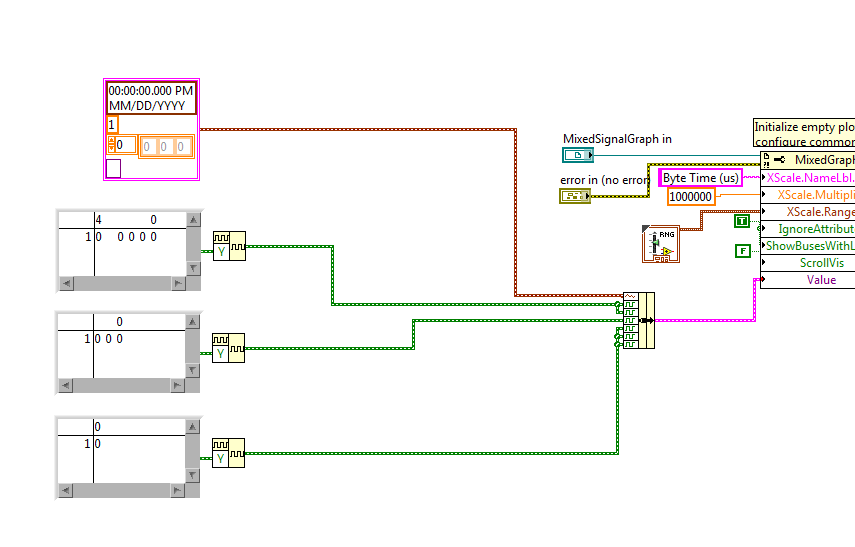
To avoid reconfiguring the graph of mixed signals, everytime I open the app, I wrote a Subvi to programmatically format the chart. I pass a reference to the graphic indicator of mixed signals and try to adapt it to look how I want. The indicator has been designed as a cluster of analog waveform 1, 2 bus waveform Digital 5 signals 1 waveforms digital bus 3 and 3 different digital waveforms. The Subvi is called inside the host VI using a statement box controlled by the 'First Call' function. Then host vi bed a U32 to the target-to-Host DMA FIFO, formats the data in the correct order and the beams while an indicator of mixed signals. During an attempt to format the chart programmatically, I get errors in property not valid which seem to depend on State. Unfortunately, the documentation of the properties seems to be quite uneven for errors I get. The Subvi attached through the following sequence:
1. configure the shared axis and shared properties (IgnoreAttributes, ShowBusseswithLines)
2 set up the area of tracing analog scale Y (superior plot, area 0? documentation is inconsistent on this point)
3 set up the area of tracing digital scale (sector 1) Y?
4. name the digital bus (3 in total, should be numbered 0-2).
5 name the plots
Correctly all steps 1 through 3, but I get an error when you try to set the Active Bus to 0--> ' #1077 Error, invalid property (Bus Active)»
I tried to set the Active plot area to 1 before setting the bus, and I get the same error.
But then sometimes if I rerun the VI host without change, the Subvi ends correctly (even if the area of the scale becomes huge and empty). The only way I can remove the errors is to set the for loops to iterate 0 times, allow the host VI run a few cycles, stop the host VI, remove the constants 0 and run again. And then there is no property errors.
I then tried to create a constant of mixed signals with the correct sequence of the empty slots and it allows to set the MixedGraph::Value property at the beginning of the Subvi. Now error #1077 occurs at the level of the active node before Plot Bus Active node. The thing first on the definition of the constants of iteration 0 does not help when the value property is an initial value.
Here are my questions:
1. the ActivePlotArea property must be configured to use ActivePlots or ActiveBusses, or is that only for sizing and moving areas of land?
2 - is ActiveBus ActivePlot to define first of all necessary to property? for example, if I have ActivePlot = 0 (for analog plot), the ActiveBus property will always fail?
3. what else is necessary for the property ActiveBus of function call?
4. why the Subvi is failing the first time but succeed during subsequent calls without be initialized does not yet reach every time after you initialize (except for loops are set to 0 and Subvi finishes once)?
5. because I show a legend of the plot, I don't want the names of digital signal appears again in the scale box Y. How can I hide the names but to allow the plot area to extend completely to the legend of the plot rather than leave a large area of wasted white space?
Hi Nick,
The reason your Subvi does not work, it's the bus you want to change do not exist when you run.
If you want to run this sub - VI like initializer, you must first initialize all of the plots you will be change.
I've included a small example of how to achieve this by grouping together a constant of analog waveform with some constants of digital waveforms and food nerd in the property "value" Mixed Signal curve.
-
Mixed Signal graphic = > line of bad names
Hello
I want to use a graph of Mixed Signal and I noticed that the digital waveforms line names are not properly displayed.
For example:
The attributes of the wave the nams of line are defined as "Name1" "Name2"; "Name3"...
On the graph of Mixed Signal, the first line is correctly called 'Name1' but all the others are called "Digital 1-> Line 0"; ' " Digital 2-> line 0 '...
Is this a bug in LabView?
If you use a normal digital chart, all names are displayed correctly.
Yes, I know that I can change the linenames with a property node, but it should also work with the attributes of waveform.
And a small second question: why are there no digital and mixed-signal graphics cards? I always build them manually...
Best regards
Reinhard
Hello Reinhard,
I think I found a link that might cover your problem. Looks like it has been known for some time
How can I assign names to my digital waveform shown mixed graphic Signal?
http://digital.NI.com/public.nsf/allkb/A6D74595D0EEFA6386257D77006537DE?OpenDocument
Best regards
Michael
-
How to adjust the chart at some point?
Hello forum.
I cut some parts of a chart of mixed signals with a slider. I have to be able to cut before and after the cursor to some given points (selected manually). Is someone can you please tell me what I need to do? I can't find all the functions related to the Cup.
Thanks in advance.
Serban
Hey, Serban,.
I found a piece of code that looks like what you are willing to do about it. Basically, you move two sliders on the top graph to change the graph on the bottom window.
http://zone.NI.com/DevZone/CDA/EPD/p/ID/4308
From a programming perspective, it takes the cursor to the position of the top of the graphic page properties and apply like the min and the properties of the max scale as on the chart at the bottom.
Logan H
-
How two graphic signals, taken at different times on the same chart?
Hello
I am trying to graph 2 files different tdm on a chart. The files are the same
Time Sensor 1 Sensor 2 Difference Sensor 3 03/07/2013 08:26:30.214 AM -0.001 0 0.001 3.2109957 03/07/2013 08:26:31.489 AM -0.001 -0.226 0.225 3.251679525 03/07/2013 08:26:32.249 AM -0.149 -0.198 0.049 3.1567506 03/07/2013 08:26:33.192 AM -0.135 -0.248 0.113 3.315462225 03/07/2013 08:26:34.336 AM -0.135 0.17 0.305 3.2682213 I need graphic of the two signals (time vs 3 sensor data from two different files). The registration of signal rate changes by file and within each file, so I need to keep the time interval between each reading, but a necessity, the two waveforms to chart on each other, no matter what day/time, each file was saved to. Please see attachment for an example.
I can read data from the file and graph several waveforms (generic of generated sine waves) on the same graph, is the part that I'm stuck how to get x/time-axis to work properly.
Thank you
Two options:
(i) use relative time instead of absolute time. If dt is not constant, you cannot use waveforms. Use an XY graph and subtract the time stamp first of each timestamp in the data/file set. Either your departure time will be zero (or 1904 if you want).
(II) draw the two sets of data in a XY Chart, using two x scales. With the right button of the x-scale and select "Duplicate scale" (or something close to it), then go to 'Settings'-> 'Ladders' and change the new scale. Now go to the tab 'Traces' (always in 'settings') and configure your two plots using separate x-scales.
-
Mixed signals with the buffer graph.
Hi I'm new to LabView and I have a really basic question.
Here's what I'm trying to do.
1. I use chart of the mixed signals to display some acquired DAQmx signals.
2. I have 3 separate field areas.
3 X - axes of these areas of land must be completely in Sync.
that is the main reason why I want to use graph of mixed signals.
4. I want that signals are displayed as table of waveform,
It's the waveform data are not deleted during update
and I can scroll to watch old stuff.
5. I also want to save the data as numbers of I can also
do all sorts of calculations with them.
Now with my vi, the graph gets refreshed and crushed
each sampling period and only a small fraction of the data I want is
shown on the screen. (I want to these fractions to get annexed by)
order of chlonological...)
I guess that it is a fairly common problem for a beginner.
I could easily do in C or Java, but rather difficult to do on the GUI.
Any help will be appreciated
Thank you!
If you want to see the temporal evolution of your chart, simply change the x-axis not autoscale under properties of the graph. You can use align your waveform in programming > wave > align times. You can activate the option to scroll by right clicking on the graph > visible elements > graphic palette.
There are many options for data backup. The quick and dirty is to enable indexing of your time loop and thread to write on the worksheet to the title of programming > e/s file > write in the spreadsheet file. Keep in mind that the file is a txt file.
Post your code for help.
-
Displays the absolute time of a waveform channel
Hello
I would like to display the absolute timestamps on the x axis of a 2D graph in the DISPLAY of the waveform channels in a PDM file. The timestamp of the first sample is stored in the wf_start_time property.
I found this article , but I don't want to generate a weather channel because the benefit of waveforms is to avoid storing the part x of the signal in the files.
Is there another solution since 2007?
I use DIAdem 2011 and LV 2011.
Thanks in advance
Hi Yohanna,
The only way to display the datetime values on the x-axis of the graph in SIGHT and the only standard way to do the graphics in the REPORT, is to create a DateTime String. DIAdem in 2011 it is much easier to do, since you can use the standard ANALYSIS function "Generate digital channel", by selecting the option buttons 'values of x-part of a waveform channel' and 'Create channel time (with absolute time reference). You can also use the standard ANALYSIS function "digital channels <==>waveform.
Brad Turpin
Tiara Product Support Engineer
National Instruments
-
data is plotted on the graph of absolute time delay
Hi all
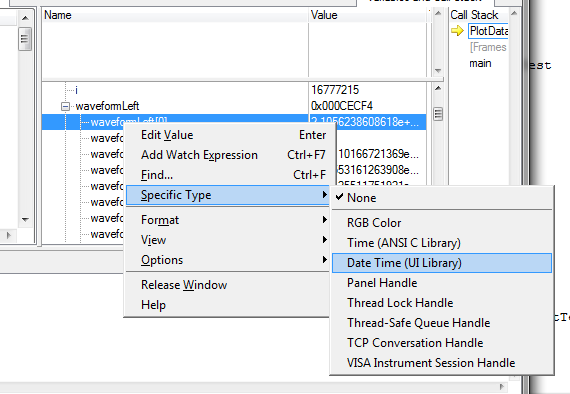
I'm plot data on a graph of absolute time and I find 2 hours difference between the data displayed by the debugger (left) and data on the graph (X - SCALE AUTO).
The time saved in ptTime, was acquired by using the function 'time' and the PC has Amsterdam, Berlin, Rome as time zone.
Here, under a screen shot that implemented the code, the debugger and the result.
The debugger is also showing the version in good time!
Can anyone suggest me how to process data in order to have the same result on the debugger window and on the graph?
A big thank you and best regards
Sergio
Question: in the CVI debugger show you, the time_t variable appears as a double, while its definition in 'time.h' is ' typedef unsigned int time_t; "so I am a little confused.
Response: I did something nonsense in this screenshot: I took a variable of type double (it happened to be a UIDateTime, actually) and configured the debugger to format as if it were a time_t variable. The formatted values that the debugger shows me, therefore, are not valid, of course. But I just wanted to show the time_t format, because it corresponds to what you have in your screenshot, and I was already suspicious that you use time_t variable to pass to the curve.
Furthermore, if you are not familiar with the way in which you can change the formatting in the debugger, this is how you do it:
Usually, the debugger can automatically pick the best format to use, based on the data type of the variable (for example, with variables of time_t). But in this case, what the debugger calls a variable "Date Time" is all just a double. The debugger cannot assume that you want to display all your double variables as a 'Date Time', and so you need to replace yourself.
Question: I was not able to find UIDateTime using the ICB type, this is the value returned by GetCurrentDateTime(double *)?
Response: There is really no such thing as a type of data "UIDateTime". I've been a bit remiss with my terminology. Unfortunately, when you're dealing with dates and hours, there are several possible representations of these quantities in the world of C, and it is important that you use the correct the intended variant you use for. In this case, the chart controls expect that you pass the time format used by the library of user interface, that is, one that is returned by the GetCurrentDateTime or MakeDateTime functions. The underlying C for this representation of the time data type is simply twice, and so it is not a good name to refer to it. That is why I used UIDateTime, but I should have been clearer than that.
Question: Y at - it a function to convert time_t values UIDateTime values
Response: Yes. You can use the functions of the programmer's Toolbox following two, in exactly this order:
CVIAbsoluteTimeFromCVIANSITime (time_t ansiTime, CVIAbsoluteTime * absTime);
CVIAbsoluteTimeToCVIUILTime (CVIAbsoluteTime absTime, double * uilTime);
Maybe you are looking for
-
Hello I have a control over the chain on my UI and I would like to make the difference between mouse different events, that is to say, to be able to differentiate a click on the outline or the label of the controller vs right-clicking on the Center (
-
HP mini 210 computer: I forgot the administrator password
Hi, I forgot my administrator password or power on password. When I try 3 times, the bios show me this number 55062924 And disable System... Please... could you help me? Thank you
-
Unable to turn on my automatic updates in Security Center
* - Original title - in regards to a new alarm when I turn on my pc and I made a few simple steps without success? Ahhh Grrrrr Why can't I turn my automatic updates in Security Center, even if she keeps alert to me?
-
Changing Outlook to Yahoo Email Client
I'm using my yahoo for all emails on windows 7 but when I want to send a web page link or page itself, my computer displays "outlook." I went to internet properties and programs, but windows 7 does not have a menu of "drop down" email to set Yahoo as
-
BlackBerry smartphones are at - it a possibility of sync BlackBerry and Google calendars?
Hey,. I use a BlackBerry Priv and work a lot with the BlackBerry calendar. For my new job, I have to use Google Calendar. So is it possible to synchronize? Thanks for help Hawkeye3