HP and/or Techtronix Multisim and GRAPHER
Is there anyway to have the results of the Tecktronix and the HP o-scopes in Multisim appear in the Grapher? Not sure why they don't, but they do not.
Hello
Impossible to Multisim to connect directly with third-party tools and import signals from the scopes in Multisim. If you are able to get information on the scope and create a file .csv with this information, you can import this file in Multisim.
I got this from another forum.
"The Piecewise linear (PWL) source accepts data as the voltage or current time. You can find this part by selecting site > component, go to the group 'Sources' then select 'Sources of voltage Signal '. Place this part on the working area, double-click it and there should be an option to open a .txt file.
Tags: NI Software
Similar Questions
-
Number of points and the number of plots for table and graph
Hi guys,.
Can someone explain to me why I get when I run the number Vi 1 2 plots for each table and graph with 6 points, but when I run vi 2 I get 4 locations with 1 point each run assuming that the same logic applies to two screws
Thank you.
When wiring of the paintings in the graphics, it is assumed that each line are several points of land.
You must convert the 2D table or right-click on the graphic and select "convert table.
-
Dynamic linking of tables and graphs in excel
Hello
We use excel to generate reports of som that got the tables and graphs. This excel file is updated every week.
My question is:
-Is it possible dynamic graphs of linking excel in indesign?
I know its possible with tables / cells, but don't themselves are no more information about this.
If not, it would be possible will be illustrator?
If I save the chart in PDF format, it is possible to link to a situation of PDF in indesign, then I can just export a new PDF to Excel every week, crush the old PDF and indesign displays the new content?
The PDF method you describe above will certainly work, but as with any link, you specify ID to do the update.
-
Insert the figures and graphs?
Hi, I'm pretty new to InDesign and use it to create a scientific document. I have a lot of tables, figures and graphs that should be inserted from various sources - documents PowerPoint, Excel and Word and JPEG. Whenever I have put a picture into my document, any text in the figure becomes blurry and unreadable. How can I fix these images so that they are clear in the document?
High quality will not work unless your images ARE high quality. Products of Microsoft support almost none of the professional standards of the industry of graphic art files, and they often export files to JPEG of the screen resolution, even if they 'think' graphics internally as online art independent of resolution. Printing of the document is a more reliable indicator of the image quality that the viewing on screen, since Indesign likes to show a "Quick Preview" to keep the screen redraws faster.
If the images print beautifully of your Microsoft product but look ugly print from Indesign, try saving the graph printing in the Microsoft program to an Acrobat PDF file and place it in Indesign, which can maintain the line drawings. And a more reliable method (but more intensive work) would be to create your graphics in a professional package like Illustrator or Photoshop (you can copy data from Excel based on graphic Illustrator, for example, which can be cryptic, but are quite powerful), in which case you can probably save in a high quality format that can be placed directly in Indesign.
-
How to stop rounding R2 value numbers and graph equation?
After inputing the values in a table, and make a scatterplot graph-, I click on 'series' adds a linear trendline and check the boxes for 'show R²' and 'equation '. The two appear on my chart, but they always seem to be rounded. My equation is always "y = x" and my ratio is always 1. Even if my partner will get the same results in Excel and get an equation like ' y = 0.9888 x + 0.00044. Is there a way to fix this? I'm doing something wrong?
Thank you!
Here is an example I did. Perhaps you could share your screenshot of dan for the chart:

-
Registers at offset and graph of waveform for function tare - strain readings
Hello users,.
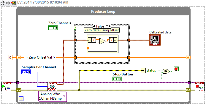
My goal is to put a strain given to zero when the strain has an initial reading. I guess that it will provide records shift in combination with the structure of the case. I tried to use two waveform graphs - showing the offset of the strain and the other showing the strain calibrated, so it will be clearer to see the stabilized strain before the reset button is set to force the strain in the calibrated chart to start from scratch. Is it possible to do?
Kind regards
Helen
Helen, you need not cross-post the question in several boards of Directors. It is a question of LabVIEW and LabVIEW, fortunately, is one of the most active panels.
So, it looks that you want to have a zero cases that calibrates your strain of reading that would be offset by reading than zero cases. Otherwise, you want to be continuous playback using the zero defined previously.
A simple solution for this is to put just a case structure within your loop of producer that is activated with a single button "channel zero". When this button is pressed, it takes the last points of data that have been read and creates a lag, so that the new data are now scaling as it.
How is this look:
If you plan to increase the size of this application, you should watch State Machine architecture or the messages in queue manager if you have a lot of data processing. This structure unique case for zero setting can only get you so far until it's hand.
-
acquire and graph of a voltage using LABVIEW 8.6 and DAQ 6020
I recently installed Labview 8.6 on XP based computer and my device is 6020 DAQ. I installed the driver 7.4.4 to my DAQ 6020.
This is my first attempt to write a labview on this configuration code, and my request is very simple.
I want to measure a voltage at the analog input channel "Ach0" and this chart. The voltage must be sampled all 1millisec.
I used a code that I found on google image search to do this, but I had got stuck at the point where I have to select channels using the DAQ assistant. The wizard DAQ says "no device supported found.
In MAX, however my 6020 DAQ is present as device 1 and I can view tensions properly he is using "ach0" data acquisition channel 6020.
The code is attached below. I use 'the edification of a voltmeter' to the page 11 of the attached pdf file.
I searched the archives of this discussion forum, there is a code for graph 2 tension, unfortunately I couldn't find the code for my application. So I am writing from scratch.
Please help me get the strings recognized by the DAQ assistant.
Concerning
Poli
According to another post of yours, that you have really a DAQPad 6020 and it's an important distinction. If you had the pci version, I think you could install DAQmx and use the DAQ Assistant. As you said, you can use the traditional pilot and in fact it is what you have installed. The pdf file you fixed clearly mention using DAQmx so information on the functions of data acquisition are not related.
I don't know if traditional DAQ examples still install, but if they are not, you will need to watch features on IO action > Data Acquisition > analog input palette. A good one is to start by HAVE acquire the waveform. A chart of output waveform and put everything inside a while loop wire.
-
analyze serial port hex data and graph time real conspiracy
Hello guys,.
am a newbie to labview and am currently working on my final project of the student, but I met a problem extracting the values of currents and voltage of hexadecimal string read to read the VISA stamp. I also want to throw the string header every time so that I can only process only the voltage and current hexadecimal string. My rope of the read data is attached. 0023-0034 0045 0132 AA55 AA55 AA55... Where AA55 is header I want to throw. The following 2 after the header bytes represent the tension, while the 2 bytes represent the current. After 6-byte header (AA55) appears again.
So far, I read the data read as attached VI visa, and I would be recognizing all assistance to extract successfully, only the voltage and current values every time the (AA55) header is read to raw data. I have read several forums observation about the covers this topic but none seem still a click. Thank you once more!
The VI am working on is attached and some failures in the print screens.
A framing error means that something is wrong with your string of bits 1 and 0 s, coming from your equipment. The start and stop bits are not where they are supposed to be. Check all your configuration settings set to ensure that they match the device. Baud rate (230 400 seems quite high), stop bits, data bits, parity. Something is probably wrong in there. That or if you have bad cables or electrical noise interfere with transmission.
Why is it you are emptying the receive buffer? Which is almost never necessary and could actually cause you to lose data or start the synchronization of your data once you've established.
I don't know what you're trying to do in this while loop inside. That looks nothing like what I was describing.
See the attached VI. I have not fully tested (after all, I do not have material sending me data). But it should give you the idea.
-
Values - reports and graphs that are separated by a colon
A checkbox element data is stored in a column, separated by semicolons.
When users try to use the function Builder to draw is a group not as we had hoped.
For example, the column contains the following lines:
A
A: B
C
C
We want the sum of the distinct values. For example
A = 2
B = 2
C = 3
Instead, we get:
A = 1
A: B = 1
C = 2
How can achieve us?
NanHello
Checkbox selections (and multiselect list Selections as well) are, as you say, stored as strings separated by a colon. It is great for data storage, but as you saw, it is not particularly good for display to the user selections. You would need to "explode" the strings in real values. How to do this depend on the output you need.
For example, take the string 'A' for example, if you need only to know the amount that each represent, you could do in your SQL statement:
SELECT ..
 CASE WHEN ':' || XXXX || ':' LIKE '%:A:%' THEN 2 ELSE 0 END +
 CASE WHEN ':' || XXXX || ':' LIKE '%:B:%' THEN 2 ELSE 0 END +
 CASE WHEN ':' || XXXX || ':' LIKE '%:C:%' THEN 3 ELSE 0 END ABC_SUM
FROM ...
(where XXXX is the column that contains the string)
But, if you see A, B and C in the report itself, you might be better off if the string into three columns:
SELECT ..
 CASE WHEN ':' || XXXX || ':' LIKE '%:A:%' THEN 'A' ELSE NULL END ITEM_A,
 CASE WHEN ':' || XXXX || ':' LIKE '%:B:%' THEN 'B' ELSE NULL END ITEM_B,
 CASE WHEN ':' || XXXX || ':' LIKE '%:C:%' THEN 'C' ELSE NULL END ITEM_C,
 CASE WHEN ':' || XXXX || ':' LIKE '%:A:%' THEN 2 ELSE 0 END +
 CASE WHEN ':' || XXXX || ':' LIKE '%:B:%' THEN 2 ELSE 0 END +
 CASE WHEN ':' || XXXX || ':' LIKE '%:C:%' THEN 3 ELSE 0 END ABC_SUM
FROM ...
If, however, values relate to records in other tables (for example, the user has selected the EMPNO - which is stored in the string - values but you want to display the actual names used), then you'd probably have to join your original SQL to the second table to display values and/or allow the user to filter by value. But it would be more complicated and can mean that you end up with more than one row for each type of master record.
Andy
-
What is the difference between the bars and graphs
For me, they are the same. When should I use one of the two, but another?
News:ghvjov$SGI$1@forums. Macromedia.com...
> For me, they are the same. When should I use one of the two, but another?One face East-West, the other North-South.
HTH;
Amy
-
TO RESET THE GRAPH AND TABLE SEQUENCE EVEN STRUCTURE IS NOT EXECUTED.
Hello everyone, I made this vi which runs automatically at the beginning and I can't use my power butoon to control this vi. Now, I want to clear the table and graph vi even when the structure of sequence is not executed as the start/stop button. And I want also when I run the program both the graph and the table should be cleared. I tried a lot of things, but as I'm new to labview I can't do. Thanks in advance.
-
Is there a way to select an area of some of the elements of a csv file and read in LabVIEW?
Hello everyone, I was wondering if there was a way to select only a certain "box" of the elements of a .csv file in LabVIEW? I have LabVIEW 2011 and my main goal is to take two tables and graphs against each other. I can import the .csv perfectly and separate each line and each column to be his own, but I have a 8 X 8 but want graphic in the middle of 4 X 5 or something like that. Is it possible to extract a table without starting at the beginning and end in the end? Thank you in advance.
Hi Szklanam,
as a CSV file is a TXT file with a different suffix, you can read a number of lines in this file. For example, you can limit the number of rows in your table of resultung. To limit the number of columns, you must always use an ArraySubset, so maybe it is much easier to read the complete CSV file and select interesting places with ArraySubset...
-
integrate image and text in the report
I'm doing a label with a logo at the top left, a chart on the side right (an arrow indicating the direction of flow)
and the text in the body of the tag, so far without success. I tried to use the generation of report vi s to achieve this, but it seems that just the 'standard' reporting rather than on a word one (no Office product on the computer, has no... Works, yech!) limited considerably, although I do not know how the do with the ability of Word template, although I suspect that would make life much easier. I really don't understand what can do the "standard" report When I set the alignment of the Image to add to the report, there is no effect on the placement of my graphics. In addition, it is an addition, which means that I find myself with the image on a label, the text on the other. I want to do is have them both on the same label, the Logo above and the arrow to the right of the text.
I tried a lot of things, including using the generation of reports "Append façade image" and make a cluster that has been written to fill all of the panel before visible, but it was printed distorted and small, similarly Append control image.
The printer is a usb Zebra TLP3842
LV_Pro,
As FAS so I understand it, the alignment entries apply only to HTML format, so they do not affect the Standard reports.
Try to put your logo in the header of the standard report. Then on your front, create a tab control, where you place your text box and graph of arrow in the direction you want to print on the page. Make the background of the transparent tab control and add the image of the tab control to the report. I think that it will be justified to the left little matter what you prefer, so play with the size and spacing of everything until it comes out looking how you want.
-
Error 50103 during continuous acquisition and triggering
Hi all
I'm ai0 data acquisition: 3 4 analog inputs (voltage) in continuous mode, display the data (tables and graphs) and data flow to TDMS files in a loop of the consumer.
The same time, I want to be able to save "time windows" with my purchase. For example, I want to be probe ai1:2 and when the voltage exceeds a certain value, that is to say 0, 5V, I can trigger with analogue reference and get a certain amount of samples (finished samples) after and before (samples before). I am aware of how I can achieve this, an example of NOR is more useful: http://sine.ni.com/devzone/cda/epd/p/id/4840 .
The problem is this: I don't want to stop the continuous acquisition which is already underway. If I try to start a new task (somehow "copy & paste" the example) that I get, as expected, error-50103, "the specified resource is reserved.
So, is it possible to accomplish this task without having to fall on reserving resources problem? And if there is not a way could you suggest a way to make this front trigger and trigger sampling?
Please find enclosed a snapshot of the code. I use a PCI-6254 with two SCB-68.
Thank you and looking forward for you advice!
Best regards
Panos
-
8753xx series read and properly calibrated chart
Greetings from the Greece,
I have a Hp 8753D Network Analyzer that I would like to order via GPIB with labview. In fact, I want to build an interface where the data of the instrument are displayed on my laptop and export them after. example "series 8753xx read and graph", does exactly what I want, but requires a file name of State as well as a calibration file name. Calibration I am used to doing so far is that manually, so I don't know what type of file to be inserted in the specific field. In addition, I have nothing but the parser, not even the calibration kit. Is there a way to create a path where the code automatically extracted labview saved state and calibration saved in the memory live Analyzer?
Thank you in advance,
For automatic playback of the files, you can code obviously hard paths in your VI. What I have done, is to have paths in an ini file which is read at the beginning.

Maybe you are looking for
-
Hello Recently, I bought my Mac, but I find that whenever I turn on the Quicktime, the entire system down easily. I'm not using QuickTime now but I would use QuickTime. Help, please. Thank you very much!
-
Re: Where can I download drivers Toshiba Satellite Pro U300?
This may seem a little silly question, but I'm not able to find drivers for Toshiba laptops online. In this case I'm after a video driver for my Toshiba Satellie Pro U300, but in general, no idea where the complete list of drivers is where they shoul
-
HP ProBook 6440 b: BIOS/CMOS admin password
Installing windows 7 Professional, I discovered that I couldn't get into the BIOS or because it was the password for protected configuration. I tried a number of things, including the installation of HP ProtectTools Security stuff and it seems that e
-
How can I get contact Hotmail to a list instead of an image and a name form?
My contact has a picture with the name under it and a star (probably means Favorites) I would like a list form so that I can mke to CVS and move. Dale
-
HP Officejet Pro 8000 Wireless printer: Always be streak on copies vertical white
HP Officejet Pro 8000 Wireless printer: Still get a vertical white streak down the photos. I changed the yellow/black printhead. Only one aid note said I should try to clean the scanner glass. Where is the scanner glass, and how to do for her? Other