acquire and graph of a voltage using LABVIEW 8.6 and DAQ 6020
I recently installed Labview 8.6 on XP based computer and my device is 6020 DAQ. I installed the driver 7.4.4 to my DAQ 6020.
This is my first attempt to write a labview on this configuration code, and my request is very simple.
I want to measure a voltage at the analog input channel "Ach0" and this chart. The voltage must be sampled all 1millisec.
I used a code that I found on google image search to do this, but I had got stuck at the point where I have to select channels using the DAQ assistant. The wizard DAQ says "no device supported found.
In MAX, however my 6020 DAQ is present as device 1 and I can view tensions properly he is using "ach0" data acquisition channel 6020.
The code is attached below. I use 'the edification of a voltmeter' to the page 11 of the attached pdf file.
I searched the archives of this discussion forum, there is a code for graph 2 tension, unfortunately I couldn't find the code for my application. So I am writing from scratch.
Please help me get the strings recognized by the DAQ assistant.
Concerning
Poli
According to another post of yours, that you have really a DAQPad 6020 and it's an important distinction. If you had the pci version, I think you could install DAQmx and use the DAQ Assistant. As you said, you can use the traditional pilot and in fact it is what you have installed. The pdf file you fixed clearly mention using DAQmx so information on the functions of data acquisition are not related.
I don't know if traditional DAQ examples still install, but if they are not, you will need to watch features on IO action > Data Acquisition > analog input palette. A good one is to start by HAVE acquire the waveform. A chart of output waveform and put everything inside a while loop wire.
Tags: NI Software
Similar Questions
-
I can measure analog USB supply voltage using Labview?
I'm basically feeding a (nominal) 5V USB power sensor, but the output of full scale depends on the real for a particular measure input voltage - what I want to do is to get labview to measure the voltage at the USB port at the same time it samples the voltage of the output sensor and then that of full scale output for that instant in time can be calculated and thus give a measure more accurate. Is this possible in labview? Thank you very much.
Haydn Barker
Makes a lot of sense, actually - probably would see a few mV dropped from the point of measurement of the sensor point... then you work with equations/remedies just to work with an inaccurate level anyway. Okay well I'll write that off as a bad idea then and just stick to the system, because it isn't now - I don't know that it will be enough. Thank you for your answers and help.
-
DAQ Assistant Express Vi to acquire and generate data at the same time in LABView
Can I run acquire it and generate the Express Assistant DAQ Vi at the same time in a LABView program? I am using LABView 2010. It's acquire and generate a NI USB-6009.
Thank you
Mary
You can acquire and generate the same VI but obviously you can't generate a wave form unless you do a single point at a time inside a loop with a sample on request and can live with low samples/s specifications.
-
Hello
How acquire and store the values of voltage DAQmx?
I tried several code example, but they can't get the chart. I don't want to chart. I want to measure exactly the analog voltage values and record these values - as an excel chart, that contains the selected channels and voltage values.
What the example code that I can use?
My hardware is NI PCI-6251.
Thank you very much.
-
6008 OR using Labview 8.6 variable output voltage
Hey guys,.
So my goal is to create an output voltage of my USB 6008 OR which can be set from 1 - 5V in Labview. (This output goes to a mass flow controller that varies its pressure based on an entry 1 - 5V) I'm using Labview 8.6 and far I used the DAQ to create analog output of fishing, but I can't figure out how to get a right voltage DC output. Is this possible? Also to measure the output so I connect the cable on the + and - or the + and gnd? Please help me!
The tension of desire is just a digital control.
You should probably just stop and take one of the free tutorials. A digital control is a very basic concept.
-
Plot the graph of origin using Labview
Hellou,
I try to plot the graph of origin using Labview. In Labview I connect and create the new model of origin for instance. Template file (.) OPJ) was created before. End of data in the worksheet then I plot the graph of origin. But I can't use OA_NewEmptyGraph.vi because it is to create a new chart. I'm trying to graph in graph model.
In labview that I found for OA_FindWorksheet.vi sheets, it's journal to find, but a cant find, a few "OA_FindGraph.vi" is - it is or made elsewhere?
Thank you
Norbert
Hi Norbert,.
your question seems to be linked to LabVIEW, while you're wrong he posted in the forum of LabWindows/CVI.
-
I want to send data using labVIEW to arduino using write visa and the process and to take action using arduino. After that, I want to arduino to send out necessary via a serial port to labVIEW which should be read using visa read and store in a chain. While I am able to write or read both individually, I can't do it consecutively. I used advanced read and write vi for checking my code, but nothing is helping. The wrong bed 'time delay before execution. " Please let me know where I can go wrong. Also is it possible to write code for hx711 using labVIEW
1. you need not "\n" on your orders println(). This command adds an end of line character already in the message.
2. you get the error because you have a loop around your reading. After the first reading (well technically, the second because of you add an extra line end character), there is nothing left in the port. As a result, you will get the timeout.
3. you should really consider using a Structure of the event. This way you just don't write and read when you press the Write button and you can also use the structure of the event to make the loop to stop. I also go up to close the port inside the stop-> value Change event.

-
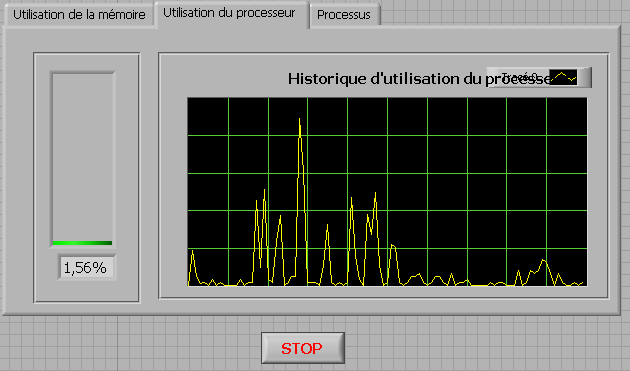
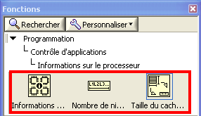
How to check the CPU usage and paging using LabVIEW
Hi guys,.
I build an application that is used to check the CPU usage and paging using LabVIEW. How can I do?
any help, suggestions or advice will be greatly appreciated...
Kind regards
Prashant
Hello
If you plan to build your app for Windows, you can use .NET classes. (System.PerformanceCounter), there is a simple example with LabVIEW:
C:\Program NIUninstaller Instruments\LabVIEW 2010\examples\comm\dotnet\SimpleTaskMonitor.llb
Also, you have several screws that you can use to verify information about the processor.
Kind regards
-
Time real ADC/DAC for SMPS by using Labview and USB
Hi all
I asked the Sales Department of this same question, so here's a two-pronged approach:
I am reserching a control algorithm for power switching, and so far, its performance simulations seem to be good. Now, the goal is to implement the circuit from the experimental data.
I've seen several NI USB DAQ boxes that seem to have the performance, I'm looking for (for example, the box USB-6211 a sampling rate and resolution I need).
The control algorithm uses the following mathematical functions: add/sub/mult/div/exhibitor and derivative/integral.
My question is this: is "strong enough" Labview take four-channel data 250Ksps, crunches the numbers in an equation and spits out the answer to an analogue on the channel, while time REAL? I'm looking for a rate of analog output of ~ 100 kHz.
Thank you for any suggestions you have!
-Rick
Hey,.
So if you were trying just to perform an input or output, then the box USB-6211 would certainly be able to treat it as the machine clock could manage the inputs/outputs, no software. However, what you are wanting to do, basically a feedback system, he will have to avoid (at least to a USB device) because you need to be able to specify Active which is the output. So, for this reason alone and the fact that you want out of 100 kHz, this device and the USB devices in general will be not an option any what software you use, LabVIEW or otherwise. On another note, you want to make sounds more like live update, not in real time, which is more on the jitter. Bottom line, for these kinds of requirements, you might need to move to an FPGA card, something like the NI PCIe-7841R would work. It's more expensive, but for your needs, FPGA will be the only option and it comes down to the latency of the bus, but also the response time of software. With FPGA, as shown in the first scheme of the following document, you basically close your software through hardware loop.
Basics of FPGA
http://www.NI.com/white-paper/6983/en
-Ryan S.
-
Deal with failure when using LabVIEW 2011 and DSC MODBUS communication
I'm currently reading from operating records a PLC with MODBUS/TCP. I confirmed that the PLC will update the values and in response to a MODBUS communication correctly by using a third-party program called Modbus Poll. However, when I try to query the PLC using the LabVIEW shared variable engine, I am unable to read the values of the same addresses that I consult with Modbus Poll.
My installation is simply to a PC directly connected to the controller via Ethernet without a router between the two. I'm using LabVIEW 2011 SP1 with the DSC module.
I opened the Manager of distributed systems OR to display the State of all variables in the Modbus Library that I created, and I noticed that the ILO CommFail permanently the value 'true '. All other variables with a 'read' access mode signal "failure of process". I tried to restart the process and stop and start the local variable engine without success. I also restarted my computer several times to see if any services did not exist, but this does not appear to have solved the problem.
Finally, I resorted to listening to communications on the network card I have the PLC connected via Ethernet using Wireshark and found that while Modbus Poll communicates with PLC, number of MODBUS and TCP packet is sent and received. However, when using only LabVIEW or the DSM OR communicate with the controller, there don't seem to be any communication on the network card.
Something that may be interesting to note is that I could communicate with the PLC and to read values with the DSM just once, when I understood everything first what address I should be reading of. All of this has stopped working shortly after. Prior to this, 'CommFail' was not generally set to 'true' with my current setup. Thinking it was my firewall, I have since disabled my firewall, but this seems to have had no effect on the problem either.
Any help on this would be appreciated.
So, I thought about it. It turns out that the IP address of the server i/o MODBUS must be set to the address of the MODBUS slave, not the local computer. The address of the i/o MODBUS server is defined by the navigation in the Explorer window projects, expanding the variable engine shared library for MODBUS and right click on the server MODBUS (for example Modbus1) item and select Properties.
In addition, the addresses seem to be shifted by + 1.
Thanks for the tip so.
-
Complete equipment of simulation using LabView, Multisim, and MAX (easy answer accepted!)
Hello, all!
Sorry, I'm new, but I checked around for a definitive answer on this, but I'm not 100% sure. I learn LabView for a physics of upper-division course. We use hardware (DAQ - MX) and a mixture of laboratory equipment - mainly stuff such as voltmeters, oscilloscopes and test setup with simple components. I also work with NIM instrumentation, but that's secondary to my needs here. So, when I'm away from the school, is it possible to make a complete simulation of my classroom work using LabView, Multisim (for my model) and the measurement and Automation Explorer (for the acquisition of data-MX)? I know I can create a circuit and drop it in Labview, but I'm not sure on the acquisition of data. I hope for what is a "seamless" reconstruction of what I do in class. I can't take a simple 'yes' or ""; as long as I know it's possible, I can find the solution.
Thanks for the help!
I wrote 'sim' screws in many situations where I need to work away from the hardware store. I think that MAX has a few features, but you may be limited in the types of signals, you can simulate.
For my sim screw, I make a copy of the original VI with ".sim" added file name. I also change the icon in a characteristic way to identify the version of the sim card on the BD. In this way the two VI have the same connector pane and are interchangeable on the BD structure. disable the diagram can be your friend here. Inside of the VI of sim, I generate the signal in any form I want. You can also add additional if necessary controls.
Lynn
-
This is my first time to use labview, I want to use the program to control the DC power for the start/stop it or set the output to program automatically.
Now I had the (supply) instrument, got a computer with labview. I know that I have to buy a GPIB cable, making a connection between the instrument and the computer. But I do not know what to buy? Cable GPIB or GPIB controller. Confused.
Thank you
A GPIB cable, by itself, will do nothing. You need a GPIB controller connected to your pc. With the NI USB-GPIB-HS controller, you can connect directly to a single instrument and no need for a separate cable. If you go with an internal controller to a pc (i.e. PCIe), you need a cable to connect the controller to the instrument.
You can also check if the power supply has other options such as Ethernet or USB remote control.
-
I am new to the ethernet communication using labview. I don't have any material. I have two laptop, I need to send and receive data through these 2 portable by using labview. Kindly help me on this.
Dennis has already said: for a direct PC - PC connection, you need a cross over cable. If you connect through a router or a switch, you use a standard cable.
-
Screenshot of Tektronix MSO4104B using LabVIEW
I am trying to acquire a screenshot of an oscilloscope Tektronix MSO4104B using LabVIEW. I am currently able to collect data from the device and have a waveform displayed on my front of VI. However, for various reasons, our preference is to capture the actual screen shot of the scope.
I have reviewed the reference for programmers for this camera and have done countless searches on Google for an answer, but have not been able to find a solution. It seems that a few people were able to reach on OTHER Tek scopes by sending a hard copy through the port of communication (GPIB, USB, Ethernet, etc.), but according to the reference of programmers for this particular device, it seems that he will send a paper copy of an installed printer, rather than simply as a stream of data to the port which can be read using VISA controls.
The other solution I've seen is to record the screen turned to a flash drive, and then copy the file via the port to the PC. However, none of these solutions seems to be available on this device... it's one of the more advanced scopes makes Tek... I can't believe it's so hard! Help, please!
-
How to program using Labview to an accelerometer
Hello:
I got an accelerometer which has digital I2C/SPI serial interface, so I bought a USB - I2C converter for data acquisition. I would like to know if I can use Labview to acquire data of com port and also program for the accelerometer to capture the data of the axis z. I have a box of white myDAQ NOR but SB. says that it is not an appropriate device to acquire before I2C/SPI signals. The datasheet of the accelerometer is in the accessory and the specification of the converter is this link: http://www.robot-electronics.co.uk/htm/usb_iss_tech.htm .
I hope someone can solve the problem for me. It is best to use the software labview for me because most of my project work is based on that.
Best regards
The f
Good and bad news. You have an accelerometer that 'speaks' I2C or USB to I2C converter, so if you connect both of them, you can send 'orders' of your accelerometer easily of LabVIEW by using communication series live that's the good news. The bad news is that it seems that you need to address your accelerometer using calls very low level, a work, I certainly don't want to face! This crys on a 'pilot', a middle piece of equipment that does all the "hard work" to take a high level order ("Please tell me the acceleration") and he translates things your device includes (including the Setup program, records, calendar, packing and unpacking of the bits and bytes, etc.).
Bob Schor
Maybe you are looking for
-
We have the latest iPhone to develop applications
I'm just request this because if I'm stuck on a 2 year contract, and I wanted an iPhone 7 when it came out, but I don't have enough money to pay the gap contract, should I the last phone to develop an application? If I don't have a phone or an iOS de
-
INTEL FORTRAN COMPILE / VISUAL STUDIO FOR THE ASPEN SIMULATION
Hi all I have little knowledge about the use of FORTRAN with application of this on VISUAL STUDIO. In fact, I know about these software because of the obligation for them to rewrite some code I had to rewrite before running on ASPEN Plus. My problem
-
SIM card slot and bluetooth conectivity.
Hello! I have a HP Pavilion notebook pc g4-1104dx. When I bought in the States, they said that it had bluetooth and a slot for sim card. But I can't seem to find one of them. I tried a search, but to no avail. Can you please help! Thank you!!!
-
BlackBerry Smartphones type in Japanese on a CURVE 9320
Can someone tell me if it is possible to write emails in Japanese language on a BB CURVE 9320? If so, how? I recently bought a BB CURVE 9320 and software, although able to display Japanese characters in an e-mail, does not allow typing in the Japanes
-
APEX 5.0 problem with jQuery autocomplete & menu widgets
And salvation,Previously (in TOP 4.2) I used the jQuery autocomplete widget. Now that I switched to APEX 5.0 I'm having a problem with it. I think that there is a conflict between the widget menu apex and jQuery menu widget.I just made a new request