Hysteresis
VI of level trigger base detection. Hysteresis
What is the level of hysteresis? Is it a percentage a voltage level or what?
Heyou wrote:
I have a voltage drops from 3, 3V she meets to 3.00. I want to start here.
Well I would set the trigger for volts 3.00 and relaxing on the waterfront down at first and work from there.

Tags: NI Software
Similar Questions
-
Measurement of the hysteresis with metal plate
Hi all. I have the task of understanding. I want to measure the hysteresis of elastic coupling. To the couple measure I two strain gages on 90 degrees (NI 9237 bridge half, II). After calculation, I now have the couple. In the other hand I measure angle of rotation of the motor with a metal plate with 52 teeth (gear). Angle of rotation I use input digital OR 9401. Hysteresis of bild, now I must on each tooth torque couted. I tried the example Multi - multifunction - Ctr Retrigg a generation sample clock Pulse Train HAVE but still graf give me the straight line. Can someone help me with this? Are there more better example for me, or clips in internet to show me how to do? Thanks before.
This is this case, the problem may be, the data acquisition card cannot rearm the fast enough triger either acquisition takes too long.
In the configuration of the screenshot I see you want to acquire 100 samples at 1 kHz. This means that each acquisition will be at least 100ms which might be too long for your application. NEITHER 9237 supports a maximum rate of 50 kHz, so my first sugestion would be to simply increase the sampling rate and see if it helps.
-
control of hysteresis (bang bang) for thermostat in cDAQ
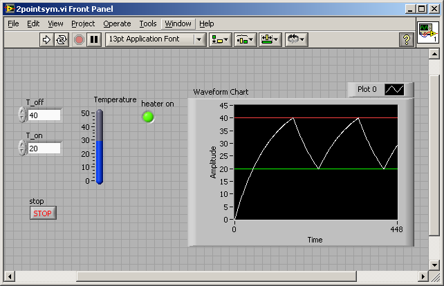
I would like to implement a closed-loop ON / OFF control with bang-bang control (hysteresis), as the ambient temperature. The loop could use NI9219 (cDAQ) unit to measure the temperature of the room feedback signal and use NI9401 (cDAQ) device such as a digital camera out of control (c). The output of control lights heater if the room is too cold (17 degrees) or OFF If the room is too hot (23 degrees). Hysteresis determines when the heating element turns on or STOP. For example, if the hysteresis is set to 5 and the temperature of 21 degrees, the unit starts at 17 degrees and OFF at 23 degrees.
An example can be found as follows
http://zone.NI.com/DevZone/CDA/EPD/p/ID/505
What I must have LabVIEW PID and Fuzzy Logic Control Toolkit and it comes free with the Labview2009 license? Can I do this without this kit?
Any help is appreciated.
Concerning
Bing
This is the façade of the 'new type' of 2 control points. The code is even simpler (select and less?) However no more assistance duties until you post your code

-
creating a loop of hysteresis-graph
Hello. I am creating as a graph that creates what will look like with a hysteresis loop. This ramp Vi up to 200 Volts at 20 Volt increments, and then it ramps down to 0, in 20 Volt decremented. I want to do is create a graph that will trace, showing he's going from 0 to 200 and then 200-0. I tried a xy chart, which I thought it would be but impossible to get data types to match. Under the State labeled "Start the Test" it shows the movement and tension. I would like to have this chart show the tension and the value of displacelement. The password is the year 2015. Thank you
You can connect an array of complex data. Or you can connect to a cluster of two arrays or an array of x, y points clustered.
-
I put my sim Droid Razr in the M and it activated without incident, but the M was not able to hold a signal 4g for the past 2 hours 1/2 that I have been putting in place email accounts, download applications etc. I keep the phone deleted and reinstalled the SIM and repressed the M and brought to the screen hard reset. I chose the option restart. After the reboot, I briefly had a 4g signal, and then fell to 3g again.
Using my Razr ever, I have a problem at home get and keep a 4g signal. Everyone knows about this problem?
I just shot to the top of the filings to the FCC for the RAZR M, HD RAZR and RAZR. The placement of the LTE antennas are completely different.
In the RAZR M, the antenna is on the top right of the unit, the HD RAZR and RAZR is on the bottom near the main antenna. LTE antennas are also a different form. This means that, in the social areas or service areas lower for LTE, according to the location of the Tower, close to your head, hands and body, it is quite likely that the strength and frequency of the LTE service will vary by phone.
You can't compare to them, and the physical design of the phone makes a difference. In a strong service area (NYC for example), LTE can be more easily accessed, as opposed to Long Island and New Jersey.
ETA: It is possible that an updated driver radio will make a difference, but this will not affect receipt of phones of the LTE service. It only affects the stickiness, the minimum signal tolerance and hysteresis for jump algorithm between LTE and 3G.
-
Card NI DAQ for SinCos encoder?
We have a RON285 heidenhain encoder that uses signaliing 1Vpp for "infinite precision". Essentially, it generates two differentials Sin / Cos signals angle and the phase between them allows you to achieve extreme precision for the angle of the encoder. You must always send two signals with a comparator hysteresis to essentially convert the signal quadrature encoder and count the pulses. Calculation of phase angle gives you the fractional precision.
(1) no matter who never used a capture card of data OR to read in the first tensions and make the calculations necessary to convert the singal SinCos until a high precision angle? If so, you are ready to share the code?
(2) make the SinCos--> Quadrature conversion on the card itself by splitting off the two singals SinCos in two other channels and specify these two channels is coded quadrature singals or do have external hardware do the comparator + hysteresis before it captures in the map?
P. S.
I just found this piece of hardware that does exactly what I described in #2 above, I get this same functionality using just the DAQ itself card? http://www.motrona.com/SinCos.html
The pointed inline Heidenhain WHAT JB interpolator is exactly the kind of thing I used other suppliers. Yes, you can introduce digital quadrature channels in a meter and other synchronization maps DAQ in a PXI chassis. 9 kHz in quadrature frequency is easily manipulated by the jury.
Setting the "pulses per rev' to 360000 and choosing degrees for units should cause the task to do the math for you, for example, when you call DAQmx Read values should already be adjusted to degrees. Personally, I do always some reason check this scaling value to make sure that there is not a factor of 4 gap because of the differing terminology between encoder and DAQmx tasks sheets.
As to limit yourself to the Tween 20 x, I tend to agree. If the Encoder error has been distributed randomly, I completely agree. But because much of it is probably more systematic than at random, there is a * chance * as some other fractional resolution might be useful. Probably a pretty small gain at best however. Unless it's quite similar cost & time probably, I wouldn't bother to > 20 x.
-Kevin P
-
PXI SFP 5105 configured Vs Acquisition VI
Hello
I recently started to use the NI PXI-5105 cards, I need to capture (noise level<20KHz) on="" top="" of="" my="" dc="" signal,="" i="" used="" software="" front="" panel="" to="" capture rising="" edge="" of="" an="" analog="" signal i="" was="" able="" to="" capture="" signal="" when="" it="" meets="" my="" trigger="" requirements="" same="" as="" configured="" acguisition="" example="" vi="" also="" vi="" recommended="" input="" signal freq="" ="" is="" 100khz,="" what="" changes="" i="" need="" to="" do="" in="" order="" to="" make="" this="" vi="" to="" trigger="" when="" the="" noise="" level="" on="" my="" dc="" signal="" exceeds="" certain="" point="" can="" anyone="" please="" help="" me="" with="" this="">
Thanks in advance!
Hey djo.
If I understand your description, the best sounds of relaxation as it can be a trigger of hysteresis with coupling AC trigger in order to eliminate the effects of your DC signal. You will then be able to adjust the amplitude of the noise that you are looking for as the level to which you want to trigger off. You can find information about the options available with the help of scanners trigger high speed OR under Fundamentals > trigger.
-
Hello community OR.
I built a VI that basically output voltage of some maximum voltage to a minimum voltage to this maximum in n steps (any user specified) and measure a voltage at each stage. It is all contained in a loop for having multiple scans.
I would average input voltages on all of the scans for each step and display it on a XY chart as the tracks VI *. My idea is to have a table built for each step and each time a sweep through this step, it adds to this picture. Then I can run it through a mean.vi and display it. I expect advice on how to impliment it. Thank you for those that you guys can give and let me know if there is anything that I need to clarify.
* Each scan through twice the output voltages, but the input voltages will be different for scanning to the low vs place due to the physics of the experience if I'm not on average scans parts.
I guess the steps are also spaced and the same for each analysis. In this case, a simple graph is sufficient, no need of a xy chart.
Due to hysteresis, you create two tables, one for the top and one for the bottom. Initialize to zero and add new values for each of the steps that happens (filling from the rear to the scan from the bottom). Divide by the number of tests at the end in order to get the average for each.
Of course, you can also create a single table for each pair of worms up and down and use an xy graph.
-
I'm under DASYLab v10 with Windows 7. I created a block with the high TTL trigger action to target an electronic unit. The intention was to use the block of e-mail to send a text alarm on my cell phone. To test the system sent 184 text messages in about a second. I really only needed a text. I had to force her to leave the app to stop. Needless to say, I passed the target of action to a message block block to save my phone bill, but the same continuous flow of reviews has resulted. have done this successfully with DASYLab V10 and Win xp and it works very well. Is this a problem of compatibility with Win 7, or is there something I'm on? I have
Tom is correct. The event "TTL" high fire continually while the event is high.
Rising has an automatic hysteresis and fire only on the change from low to high.
-
Need a little help to understand the features of measure or-scope
Hi taurna,
The Stats.vi measure will take a measure through the complete waveform acquired in that particular record. Help on the Fetch Multi steps Stats.vi:
The waveform on the digitizer calculates waveform measurement is to
an acquisition that you launched previously.But according to the measure of the positive width, you see only the first pulse width. The definition of the measure can be found below (note the use of 'first two mi'):
Positive width
C/C++ equivalent: NISCOPE_VAL_WIDTH_POS
The time difference in seconds between the first two mid reference
crossings, where the slopes are positive and negative respectively. A
Digital hysteresis is used to find the points.Help on the num in the statistics section:
Num in stats returns the
number of measurements to calculate the statistics.Saying "1" here, he did a single measure on your single purchase you took, since the while loop was taken out of your code. If you want several measures to make, you need several acquisitions.
-
Hello
I am raw data filtering, then look for the max/min of the three channels, which is output to a file. The timestamp I want is max/min of the first string, but I want the max number / the other two channels in a 100-minute samples of max/min of the first chain and not only the corresponding timestamp max/min of the first string (we have some information of inertia in our configuration that we are trying to capture these other two channels).
To do this, I use a module Max/Min for three channels, with an additional TTL output on the first string, which is managed by a triggering of the sample module, then the module locking. This allows me to capture the Max/Min values for the three channels and output to a data file, when I correctly specified the hysteresis values in the Max/Min module and trigger the sample to get less than 100 samples and start at the beginning of the event.
However, I do not get the correct timestamp for the max/min of the first string in my output file, it seems to be the timestamp of the data block in which takes place the max/min (the timestamp above the correct timestamp from 100 to 300 milliseconds). How can I get the correct timestamp for this task?
I am using Windows XP Pro SP3, DasyLab 9.0.2 basic (Yes, we're going to be upgraded, but not this week
.) See attached sheet for more details.Here is an example with a generator.
Use of the *. DSA to open in V9 file. I'm not 100, some that it will retain all settings, but it's a good start. The *.DSB file is DASYLab 12.
-
How to activate the module message once per trigger event?
I use the action to display a message and possibly send emails when a triggering event occurs, say that a temperature exceeds a limit. Currently when a product (high TTL of a pre/post trigger) trigger module action continues to produce messages every minute in the message window, continues to send messages to the log file and would continue to send emails every minute if I had the Active Messaging module. I wish I had the messgae displayed once. Any help would be appreciated and thanks.
You must use Rising Edge to the event, not TTL high. It has an automatic hysteresis because it seems to change from low to high, not only from top.
-
min/max with outputs ttl statistics
This is a weird problem. I have attached the worksheet because it is difficult to explain the problem. First of all, let me explain what this thing is supposed to do. A generator of signals outputs sine 5Vp - p, in addition to four. After being added, I use a module of statistics to determine the Min/Max. All I need is the maximum, the minimum is ignored (I'm only looking to the + pics). The + peaks are evaluated to identify uniquely to the final output, which sinewave (s) have been entered in the worksheet. Since I finally need 16 - bit I had to add a scalar unit (scale module) to create the entry 16 (max 15 son allowed an output) by expanding the 15th input to two outputs. I see the expected level of TTL is issued by the module of statistics on three modules Y/t diagram. This tells me that things seem a little work at the exit of the module of SEO (the values of hysteresis in the stat module need to be tweaked to produce all the unique values (16), but it works at least. The problem is that the module of bitmask (set to combine tips - 16-bit conversion for a wide release) generates no output regardless of sinewave different combinations of entry. I thought that I have had set a good example of C.J. provided. I hooked of DMM to also monitor the inputs to the module of bitmask (called 16-bit encoder) - I can't get the digital multimeter to display the output of the module of the stat, but the modules Y/t show the output TTL values there. Both show the modules expected to show which is output, but don't--that intrigues me. The frequency of the sine wave is set to 1,2,4 & 8 Hz for debugging, so I know it is not too fast for the DMM display - I proved this by connecting the sum as an input for the senior DMM sinewave and it displays the voltage changes without problem.
Thus, the two questions are: 1) why the DMM is not working at the release of the Y/t modules or Module Min/Max of Stat? (2) why the bitmask Module cannot evaluate its entries? The added sine wave is continuous and constant phase.
Any help would be appreciated. This has really baffled me, trying to debug.
It dawned on me that the DMM is placed where they will not work because they are supposed to show a too short period of tension. They would appear between 5V and 25V depending on the number of 5V wfm summary, but each TTL output, they try to show are nothing more than the duration milliseconds--not a good application for a DMM. Now, it's just a question of what is the problem with the 16-bit conversion package around!
Any suggestions on the problem?
-
Min/max to accumulate dasylab peaks? Is this possible?
In collaboration with Dasylab 10. I'm looking to collect peaks min/max on a form of sinwave we will run. Is this possible? If so, how? Or I have to just to oversample and sift through data?
Thank you!
Select this option.
Use the statistics module called Minimum / Maximum.
This will display the value (you choose minimum, maximum or both), or will display a TTL signal, with a peak TTL (5V) to record highs.
Adjust the hysteresis value to avoid detection from noise and spikes, or use a moving average to smooth out the signal.
-
How to read two files (one updates every second, the other is constant) simoltaneously
Dear all,
I'd appreciate if someone help me.
I want to read two files, one is the temperature that updates every second, and the other is energy hysteresis that has specific lines and is constant.
I had a program in the discussion forum to read a file as it is updated. I checked this program in my case and it works.
Then I added playback file hysteresis energy to the existing file. But while I run the program, the energy hysteresis file is read with all the lines.
But the goal is that every time the updates of the temperature, I need to read a line of the file hysteresis energy.
in this way every second, so, I have a new temperature data and a row of the other file.
I tried to use 'for loop' inside the program, but it did not work, because the temperature reading will stop until that end of the loop.
I joined the program.
Could someone help me how read only a row of hysteresis energy file every time that the temperature updated?
IS that what you wanted to achieve?

Maybe you are looking for
-
Options/general/show my Home Page is broken in version 9.0.1
I searched this topic in Help and the most recent responses were talking about 3 months ago to version 6.01. I have version 9.0.1. In Options/General I selected for when Firefox starts "show my Home Page". One of the other options is "show my windows
-
I have an iMac (I forgot which model) running El Capitan. It has been a very reliable machine. Only, I restart the machine once every few weeks, but yesterday when I stopped it, I could not it restarts. I have four user accounts running on this compu
-
HP nc6230 won't install windows xp pro.
I have a HP nc6230 with a new hard drive. I put my windows XP Pro installation disc in the DVD drive and started the game up. The responsible Installer drivers to begin the installation and happened to format selection screen. After formatting and pa
-
Last updated Photoshop CC settles mistakes 160 and 184
It downloads all the way and then says Installation failed.At first I thought it was because I just upgraded to Windows 10. I went back at 7 and Photoshop installs it always. Uninstalled photoshop and creative cloud, reinstalled creative cloud, Photo
-
JDeveloper 12.1.3Benefits: I tried searching the forums but I do not know how to use appropriate terminology to describe what I see. Basically, I have a table of the ADF that returns the results of the query. The table is read-only with unique, selec