I2C sbrio 9636
Dear all,
Greetings
I need assistance to implement an I2C protcol in sbRIO 9636 (KIT of RIO could), I try one of this website (http://zone.ni.com/devzone/cda/epd/p/id/4063) after moving to screw for my kit and deploy it I couldn't have expected results, as shown in figure (start condition) instead, I got the figure of output (output). any suggestion? Help, please...
Thanks in advance
Mustafa
Tags: NI Hardware
Similar Questions
-
Data acquisition on OR sbRIO 9636
Hello! I'm working on my school project and I do the acquisition on OR sbRIO-9636. How I choose the sampling of acquisition period? I work as an example on the Web site OR below:
http://www.NI.com/Tutorial/4534/en/
I can't understand it on what sampling period should I put in Host.vi and in Target.vi in order to have the good acquisition? For an example, I would like to have period milliseconds 10 sampling. The configuration of loop-time in Host.vi and how Target.vi?
Thank you
Chupka,
Yes, the calculation of sampling looks good
 this way, find all your data every loop, but you want to make sure you have a case to avoid FIFO overflows if you read each data point. With regard to the loop of the host, you do not want make sure that it is superior to the host loop so that if you encounter the jig in your curls, you won't have the time.
 -
Interfacing engine Lego NXT sbRIO-9636 Eval Board
Hello
As a newbie to sbRIO, I would build a simple Quadrature counter.
Recently, I attended the great build your own Embedded system workshop and have a sbRIO-9636 running a updated the Quadrature counter sample project AND originally designed for the sbRIO-9631. He works a lot using the digital encoder built into the daughter card.
Then, I want to use a Lego Mindstorms NXT motor (PN 9842) encoder. I will feed the outboard motor so for now I just up/down count the encoder. Here is the wiring that I intend to use on the map of my daughter:
Channel that has the encoder (yellow wire) will go to DI2
Channel B (blue wire) of the encoder will go to the DI3
Common 0V (red wire) goes to DGND
+ 5V (green wire) will go?So my question: is there a point on the map the sbRIO-9636 girl, I can securely connect to for + 5V power of encoder? Moreover, these colors of son are Lego Mindstorms extension cables when they are cut and stripped.
Any help would be appreciated!
jimmyservoAccording to the quick reference for the sbRIO 9636: http://www.ni.com/pdf/manuals/375933a.pdf
There seems to be + 5V on 49 and 50 of the J502 connector pins. This connector is available, or you use a daughter card?
Other options would be more hackers IMO, such as the drawing of the USB connector 5V.
-
Hello
So I have a sbRIO-9636 and I worked on it for a while. Have had no real problems with it, but the other day when I started it up it is just on the network. After checking the hardware (cables and switch), I noticed that the connector ethernet LED are lit (green) as soon as the sbRIO is turned on even if there is no ethernet cable connected. If I plug in an ethernet cable activity LED begins to blink continuously. There is no sign of her on the side of the switch. The port State LED is off and there is no trace of the sbRIO MAC address. I tried to put in safe mode, but the same behavior just keeps repeating itself.
Needless to say, it does not appear to the MAX and he cannot be crazy.
I'm about to get your hands on a cable to try to connect to the serial port and see if I can get some information about the function of the Console, but I thought I'd check if anyone here have seen this behavior a sbRIO and perhaps successful solve. It's sad to say, I did not have much hope for unity but maybe worth it.
Thank you
Nimgaard
Nimgaard,
There is nothing of National Instruments can recommend to repair this unit. I would recommend calling our support and explaining what happened. They will know if the unit is still under warranty and can you get in touch with one of our RMA coordinators who can help you deal with this. This option can be less expensive than buying a new unit.
-
"For more specific class" does not not on sbRIO 9636
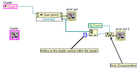
The application that I am forcing me to programmatically access arbitrary components of a nested group. Currently, I am doing the browsing the cluster using his property [] node recursively controls. Currently, my accessor VI to accomplish this works very well on a normal PC but does not work on my target in real time, a sbRIO 9636.
After some research, I determined that the function "To more specific class" does not work on my target in real time. I have attached a code base that shows the heart of the problem. It works fine on a PC but will return an error 53 when running on my target in real time.
A few questions:
(1) is 'To more specific class' supported on the sbRIO 9636 or not?
(2) if it is supported, what am I doing wrong?(3) if it is not taken in charge, what are other methods for access by the arbitrary elements of a nested cluster program?
(4) if it is not supported, why LabVIEW allows me to place the feature even when the sbRIO 9636 is explicitly selected as my goal in my LabVIEW project? It seems prudent to restrict its use, if it is not supported. My day job has been effectively wasted because of this problem.For reference, here's a few previous discussions
Thank you
JAnthonyThe other posts are correct, because it is currently not possible to use the function on a real-time target. This is a known issue and is being investigated for correction, but currently there is no work around. It is available on the pallets that this behavior is not intentional and should work.
You have described your application requires that recursively through a table and access to specific data. Does this mean that the Data Structure might be different when the vi is run and you need to adapt to a changing data type? If this isn't the case, then all you need to do is to get the value of the reference and then ungroup the cluster as needed then store the changed values to the same reference.
If you're going to have to settle you will encounter difficulties to be determined pragmatically you should do but I have a suggestion. Create a cluster with an enum and a Variant. You can use the enumeration to set the type of the variant in question. He chooses the type to convert the variant according to the code. It is a similar structure, like messages in queue manager and his messages that happening except that you will be passing a reference to this group that has both the message and the payload in one. The reference could be used to get the value and then the code must only be written to accept the Cluster of Enum and variant you can then convert the variant to the appropriate type for later use. For best performance, you also use in Place of the Structure element.
It's only a means potentially accomplish what you want. If you describe your program and needs more in depth, we are able to offer a more suitable solution for your application that does what you need. I wish you a nice day!
-
Guys,
I have a 1 sbRIO-9636, which was part of the assessment package. I took the part of high level (circuit that allows you to interface with a few DIO AIO) and have only the Board of Directors. then I advanced and bought some fo the Accessories:
Part number 154041-12
Part number 153158-10
Now Iam stuck trying to find a block of endings (look like the cb-50 i/o (p/n 776164-90), but for this Council so that I can interface with the DIOs and AIOs.
I learned by a seller of NOR does not make this Terminal or knows what third-party company makes. (this time I bought these pieces through OR which has baffled me)
If anyone knows how can I get a connection block that uses the robon 50 cable I bought I'll greatly appreaciate it.
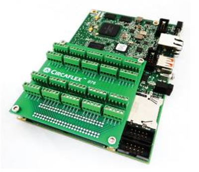
Just remembered... NEITHER Alliance Partner Cyth Systems built a block of board-to-board endings for headings 2 x 50 pins. The product is not on their Web site the last time I checked, but the model number is CFX-076. Their roommates until the Single-Board RIO Summit. If you need a version that uses the 50 pin cable to place the block of remote connection, they may be able to work with you on a version without the connectors the connectors on the card-board replaced with cable connectors.
-
Looking for a map of derivation for the IDC sbRIO-9636 headers to access model IOs (or block)
Hello
I have a sbRIO-9636 and you want to use for prototyping of something. It has 2 headers of IDC 50 pin access to the many inputs/outputs. The problem is that pitch IDC Council is 2 mm instead of the more standard 2.54 mm (0.1 "). I want to access these IOs model, but all the map of derivation that I can find is 2.54 mm (side of header IDC). I did a lot of google search today but no luck so far.
Is there an easy way to access these sbRIO IO model or a block of endings of the?
Thank you in advance!
Hi TailOfGon,
I know that the product manager for the Single-Board RIO is still working on getting this displayed product to ni.com, but NEITHER has recently published a map of derivation IDC cable to the connectors of 2mm on Single-Board RIO. A single derivation card can provide a Terminal screw to the headers of the e/s analog and e/s digital at the same time. The Board match the holes of the sbRIO-962 x and x sbRIO-963 and can be mounted on the underside of the Single-Board RIO with short cables of 2mm (included) to wrap around the map of derivation.
You can add the PN next to the cart on the Web site of NOR, or you can call and place an order:
sbRIO 2mm IDC connector Breakout
784507 01In addition, a partner of Alliance, NOR Cyth Systems, built an escape from edge to edge for headings 2mm on Single-Board RIO as well. You can see my previous post, including a photo of their derivation here business card:
http://forums.NI.com/T5/LabVIEW/sbRIO-9636-question/m-p/3021431/highlight/true#M863321
Kind regards
-
How to CAN with Sbrio 9636 interface
Hello
I use Labview 2011 and SBRio 9636 to communicate with controllers EPOS2 Maxon, who uses the CANOpen protocol for communication. Since then, SBRio has only library CAN shipped with it I just use it to monitor a network of communication already setup. What communication happens even within the network that sbRIO fails to receive any image. I run the example of unique input output for this purpose. The connections are checked and the resistance of connection on the bus is 120 ohm. SBRio penetrates "Error Active" mode and starts running. We also find that the Commission also triggers an error in one of the EPOS2 that is connected directly to the card. Can someone tell me why this happens? Y at - it that anything left to do? I find it difficult to download images and help send the front and block attachments Panel. P. S.
Hello Surajp,
I also have the problem with the sbRIO CAN communication, but at least I could receive frames just some time lost some.
I found in your window block, you set listening only? TRUE, this is not correct, this must be set to FALSE, otherwise can not read any CAN CAN - bus framework.
Here is the description of the help file.
Listening only? property configures if the interface CAN transmit all information CAN bus.
When this property is set to False, the interface can transmit frames CAN and acknowledge the received frame.
When this property is set to True, the interface can transmit frames CAN neither acknowledge receipt CAN fit. Set to True allows a passive monitoring of network traffic, which can be useful for debugging scenarios when you do not want to interfere with a communications network.
Hope this will help you.
Qi
-
Hi guys,.
I use a SBRIO-9611 to control a few shavings DAC using I2C. I did some research and found the link below.
Unfortunately, I'm using 8.5.1 both for my FPGA software and in real time. I need a kind soul help me downgrade 8.5.1 code so I can open it.
Thank you
Ray
https://decibel.NI.com/content/docs/doc-1151
Hi Ray,
Here is the converted project
Concerning
-
Hello world
I'm new to the part during a real-time/embedded Labview and I'm just starting to play with the RIO evaluation kit.
I stumbled upon a phenomenon that I do not understand... So maybe it's a stupid thing, so I apologize in advance.
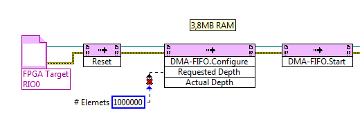
I have create a FIFO on the FPGA target (configured to Traget - to - Host DMA) and put the UINT16 5Million of a FPGA loop values, as soon as possible. Now, amazingly, I can read either with a VI on the chassis in real time, but also with an identical VI located on the PC host, even with similar performance.
In fact, I don't understand where the data are buffered and how the PC can access. I thoght the FIFO DMA memory needs to be on the RT target, right? So, how the data comes to the PC without a RT - VI? I guess that this method of data transfer (FPGA-to-PC) is not a use of FIFO, right?
In addition, when I check the property of "Possible elements" of FIFO in the PC - VI or RT - VI, I get numbers approximately 8000 to 10,000, while FIFO is configured with 1023 elements only.
How is that possible?
(Btw.: I realize that I'm losing a lot of data and the FIFO is small.) Yet, I want to first understand the points above).
The project is included in the ZIP.
Best regards and thanks for your efforts,
Joe
Hey Joe,
NEITHER offers a service called NI RIO Server. This service is installed with LabVIEW RealTime on your target in real time and allows you to connect to the FPGA of the cRIO/sbRIO from a computer.
I can't find a lot of information available on the internet, this page only:
How to make the devices to access RIO on a computer connected to the network? -National Instruments
http://digital.NI.com/public.nsf/allkb/43F81436B97AEE28862573D40069F440He is the Francis, why you are able to run the same program in real-time on the RIO and the development computer. It is also the reason why you must enter the IP address of the target in real time on the program running on the development PC. If you run the VI on the RealTime Taraget itself, it is not necessary to enter the IP address.
Some information on the size of the FIFO:
The FIFO is not only a buffer. A buffer of contains two FIFO.
A buffer is located in the FPGA itself. It is unbelievable small (1023 elements by default), but this buffer is super fast. The size of this buffer is configured as part of the LabVIEW project. You can increase the number of elements in the buffer zone, but you will never be able to achieve an elements > 20K buffer size due to the constrained resource of the FPGA.
The second buffer is located on the site in real time of the RIO. This buffer can be bigger than the buffer on the FPGA, usually 10 x or more. You can configure the size of the buffer of site in real time by your LabVIEW Code on the part in real time.
Best regards, Stephan
-
the use of camera web usb on sbrio 9636
Hello
I want to use logitech camera / webcam C170 on single board rio sbRIO9636 to the perception of the vision.
(a) is this unit supported by sbRIO9636, page on http://digital.ni.com/public.nsf/allkb/33131C00626C5B6E8625788D00025FC1 shows that the manufactured by Basler and axis IP camera are supported.
(b) are there any drivers must be installed on sbRIO and where I could find the drivers?
(c) Is there examples for the usb camera capture?
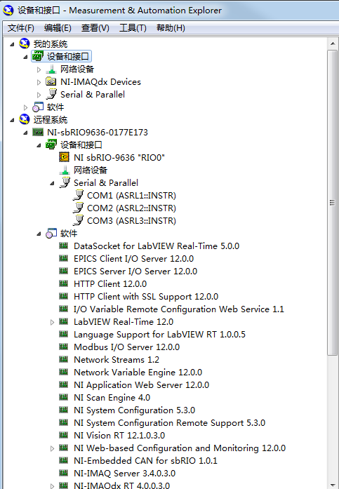
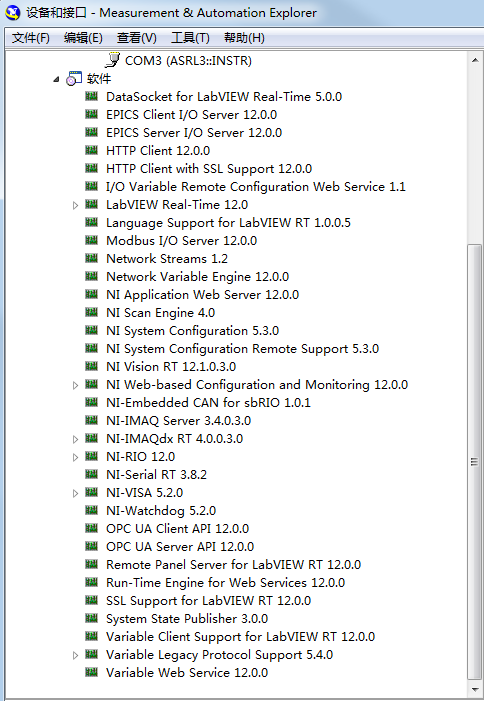
The software is installed in sbRIO9636 is displayed as shown in the pictures:
Thank you!
You will not be able to use a USB camera on a target RT LV.
-
Someone at - it an example of LabVIEW for I2C communication to read/write an eeprom?
I use sbRIO-9636 with FPGA.
I already tried with the "Advanced I2C" example, but it works...
Can someone help me?
Another suggestion:
You know about the VI package manager? There, you can install an application open source I2C & SPI API (worms. 3.0.0.22). It is an easy way to implement a system of Bus I2C on an FPGA target.
In this way is a little bit smarter.
Maybe you like it.
-
XBee use sbrio communacationwith
I'm trying to connect xbee to sbrio and I have not read the data from xbee.i connected to the serial port and I have configured xbee but I try to read data from the xbee use sbrio 9636 and how to read data from the xbee use sbrio pls help me?
-
I2C + class motor from examples of robotic controller
I try to combine (i.e. to use together in the same project) the motor controller class used in "Starter Kit 2.0 Custom FPGA" with I2C of "Communication I2C - sbRIO" in the examples of the Robotics module.
I have already combined the FPGA code in a single FPGA VI and have tested the two individually. When I go to use them together, I can't use the same FPGA VI reference because one is designed using a FPGA VI reference in dynamic mode (engines) and the other uses an FPGA VI reference that isn't in dynamic mode (I2C).
So, what should I do? I was going to try to convert the I2C in dynamic mode, but the only way I'd be able to do is to open the FPGA reference in each Subvi (since I can't bind to a type in the dynamic mode definition). It also looks like trying to convert each other would be a nightmare because it would require to change the classes also (which is a mystery to me).
P.S. I have sbRIO-9632 (Starter to be transferred to a large robot Kit)
Nathan_B. . I met the same problem, when I mixed the two codes.
And the only way I found to resolve this problem, configure the device "FPGA" in dynamic mode, then create a control and change of the Subvi in relation to the 'I2C Protocol', with this command (replace the input and output of the 'Sub - VI' - reference fpga). In this way, I realize the work programme. (see attachment).
-
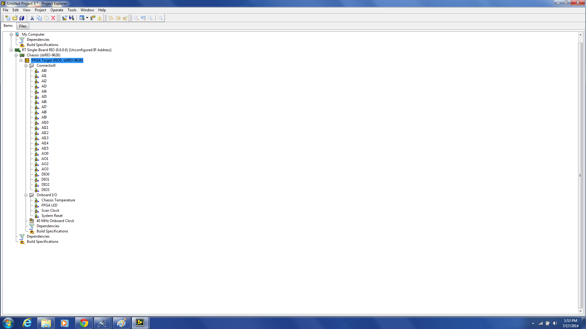
Lack of Ports on the model of project sbRIO 9626
Hello
I'm working on the development of FPGA software for the sbRIO 9626. Unfortunately when I create an empty project with the wizard, I get only Connector0 without Connector1 or Mezzanine ports. It seems that something might be wrong with my assistant. Can someone give me some advice on how to fix this? I need to access those other 100 IO or more.
Thank you
Zach
You must add a Mezzanine of RIO to the target FPGA to expose the IO CTMR. Right-click on the FPGA target and select new > CMR (or similar, I do not have LabVIEW in front of me). In the follow-up dialog box, you can select evasion DIO 9694 CTMR to expose all the I/o, or I think there is an option for RMC custom which also exposes all the OID.
Connector 1 is not available/populated on the sbRIO-9626. These DIO lines on connector 1 to the sbRIO-9636 pass alternately to the CMR.
Kind regards
Maybe you are looking for
-
HelloI have windows 8 x 64installed almost 1 year ago and my hp probook 4520 s is 2.5 years and work great in this period5 and graphic CPU is amd hd 4300/4400health, autorun and dump file of check are all attached with your exclusive report file.I ha
-
WINDOWS XP PROFESSIONAL NETWORKING PROBLEM
whenever I try to connect to the other computer on my network, the window opens asking for the password set by the other computer, so that no password is defined by the other computer. ANOTHER COMPUTER CAN BROWSE MY SHARED FOLDER BUT UNABLE TO CONNEC
-
have been computer usingbthis for a while now, so have no problem just want to know if I can install update on upgrade of old
-
Virtual defense Center showing not detailed network information
Summary dashboard shows all the great stuff, but when I drill down, no detailed network information is displayed. The only detail I got is operating system info. but no host address IP Source or dest. What could be wrong? What to check? Running the l
-
I can't create or view saved and Favorites in kuler using CS6
I'm new to Kuler and have not "used before so it might just be me, but I shopped the answers." With the help of Illustrator CS6 v16.2.1 last updated CC. Finally find the choice of elusive Panel in window > Extensions. Now I have access to the Pane