IMAQ line guage
HI -.
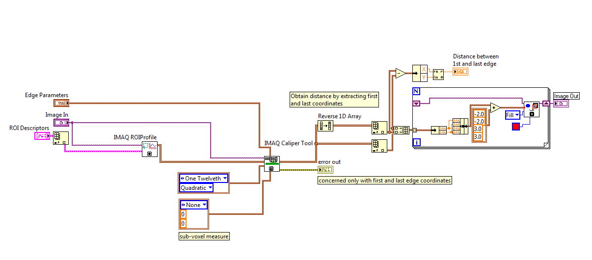
I want to superimpose the edge points found by using the IMAQ Guage VI line, very similar to how it's done in the "Example.vi of edge detection.
However, outputs only to the IMAQ line Guage VI are the distances. I can use the IMAQ Edge Tool 3 to get information of edge overlay, but it is not clear to me that the edge information provided by the IMAQ Edge Tool 3 is compatible with the calculations of the IMAQ line Guage VI. I need the subpixel accuracy.
Can someone let me know how we can do this with IMAQ line gasoline?
As another note, I tried to use tools IMAQ himself but was to have some very strange results for distances, that's why I turned to IMAQ line of gasoline, giving me good results.
Thank you
Don
The fixed. Missing IMAQ ROIProfile that is necessary to get the entry of correct coordinates for the caliper tool. But I think it would be easier to have just the edge information outgoing IMAQ line Guage VI since you can see that I had to manually write the code to get the first and last edge and remotely. This information is certainly somewhere in the line of gasoline VI. NOR would just add edge as output information.
Tags: NI Hardware
Similar Questions
-
Hello
I am a newbie to labview and try to use the function 'line IMAQ gauge' but I do not yet.
Could someone send me examples or applications, if there is everything, including "IMAQ line gauge" function?
Best regards
Hi abligi,
Line gauge - IMAQ is a combination of caliper IMAQ (to some extent) and the distances from point to point IMAQ
-As you can see in the help file, you can get to a Point, edge-edge, edge-point and point-edge distances.-Fixing simple example with image to give away. Try to play around by changing the coordinates of line and the type of measurement you need.
-The snippet also added.
-
(Filter?) Lines of displayed Image IMAQ
I use the Acquitisition Vision of February 2015 software to capture images from a series camera Basler Ace.
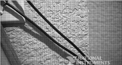
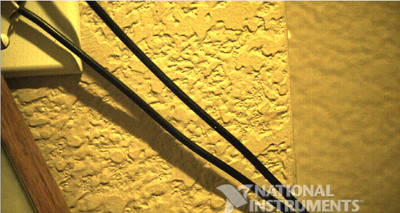
When I read an IMAQ image out of the buffer and display it in the front panel, it looks like the image in grayscale below. There are a lot of horizontal and vertical lines in the image. How can I get rid of these lines? I found examples online of making images in grayscale that I can't use because I don't have all the features cast in my range of vision. An example I am SEO: http://digital.ni.com/public.nsf/allkb/ED42C55C29B9B34C862570A60079952E
I guess they are probably color for the Bayer filter filters? See how the colorized image is much better after going through the filter of Bayer VI. How to make a grayscale image that looks as smooth as the color image?
No, you must purchase and install the Module OR Vision Development, which is separated from the Vision Acquisition drivers.
Bruce
-
Anyway to adjust the weight of a Coverstitch IMAQ and IMAQ Overlay line?
Is it possible to adjust the weight of a Point of recovery IMAQ? I find it odd that this is not an option.
If you mean you want a greater 'dot' or more online, as it takes a bit of work, because this option is not built on the.
Instead of using the overlay point, use the the oval, then you can set the RADIUS want. or you can draw two lines (one vertical and one horizontal) crossing the coordinates of your point.
I know... It's a bit tedious, but that's all I have in stock.
-
Hello world
How can I reduce the zoom of the select line IMAQ in Labview? (You can find it in the model---> Vision and Motion---> visionique---> Select Region of Interest---> Select line)Click Shift + Zoom tool be to zoom out. Without change, it will be to zoom.
-
Match pattern IMAQ 4 to superimpose several lines 2
Hello community OR,.
I have a problem connecting to the match pattern to superimpose several lines 2.
I want to track an object from a video webcam.
In this help http://zone.ni.com/reference/en-XX/help/370281U-01/imaqvision/imaq_match_pattern_4/ it is said that the Matches (Pixels) (Bounding Box) must be connected to the superposition of several lines to the end of line Points. But I can't take the bounding box only. I tried the unbundling of the table 1 d of the clusters, but I can't do it.
Any help is appreciated. I can post a picture of my code if requested.
Thank you
Marwan Sabry
I'm sorry, it's an array of clusters.
-Therefore, index 0 for the first game.
-unbundling with name for encompassing and then pass it to overlay vi. -
IMAQ OCR read text - read several lines
Hello
I'm trying to read multiple lines of text that are placed in different areas of the image from an image.
So far I used for each line a different OCR read vi with an another KING descriptor text.
Is it possible to use only an OCR read text vi for all lines and make the block diagram more sleeker look and application work more efficiently?
I really need to use 20 text reading OCR, popular vi with 20 recatangles for the reading of 20 different lines?
Thank you
Shahar
As far as I know - no, its impossible.
Otherwise, you don't need to put 20 reading OCR instances on the BD - you can do it with ' loop for "with 20 iterations.
-
Hi all
I thought that I could transfer it here because it might be a more appropriate forum. I have a bit of time pressure, so I hope someone can help me. I'm having a problem with a program that I wrote to acquire and store images from a camera to linear scan.
My camera (SUI Goodrich, 1024 pixels) is connected to a card framegrabber (PCIe-1427), which is connected via a RTSI cable to a PCI-6731 card attached to a SCC-68 (series) connector M. My goal is to drive a mirror galvanometer scanning and acquire images from the camera continuously on each scan. As the galvo scan will be the frame of an image (1024 pixels x 1024 lines).
I managed to do it (I think), as my direct purchase program works exactly as I expected. However, when I try to save the images, I noticed that for a larger number of images, the starting point of the image is shifted the same amount for each image. I'm not really sure what's going on, it seems to me that there is a delay in the use of the VI "IMAQ set up buffer" when a larger number of buffers is used, (or even 100). Is it possible that my hardware trigger does not wait for all buffers to be configured before you start to run?
I would really appreciate any idea or ideas that anyone could have on this issue.
Sincere greetings,
Gill
I fixed the problem by doing that I don't use actually 1000 stamps to save 1000 frames. Program works if the number of buffers is lowered.
-
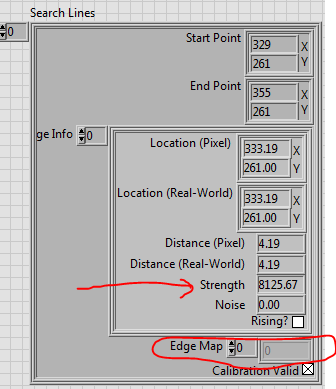
IMAQ rake 3 VI - map Edge returns empty array
Hi, I have a U16 image that requires analysis using the rake 3 VI IMAQ. Out of lines of research, the strength is indicated for each point along the line of research, but the card edge (I expect brings together the strengths and assembles them in a table for each line) returns empty. Anyone else seen this?
Check the source of the "optimized" for IMAQ rake 3 Mode...
-
Hi all
What does IMAQ start? On my eval of camera position, it fails in certain circumstances, and I am trying to isolate the cause.
Reminder: There is a rating system provided to me by MAY. When I use it as they delivered, it works fine. But of course, I need to perform very differently than the design of the MAY, and that's where the trouble starts.
The system is a Lenovo ThinkCentre running Windows 7 Pro SP 1 64-bit.
NOR-1433 PCIe framegrabber, two Camera Link cables running to the eval Board.
LabVIEW 2010 32-bit version,
NOR-MAX version 5.5.0f0,
NOR-IMAQ version 4.7.3,
Camera files 3.0.1 generator
The eval system was originally designed as a step 4, CL Medium. To illustrate a concept we develop, I want to run 8-tap CL full (really, I want 10 bits 8 tap but that's another debate). I used CFG to change the original file of the ICD and saved as a new file. When I use NEITHER-Max to move to this new camera file, the program fails when IMAQ Start is called, error -1074397153 is returned. «NOR-IMAQ: impossible to detect a recognizable video source'.»» I'll join the two files from the CIM.
I see two possible culprits:
(1) IMAQ start is reading of registers on the camera and find something inconsistent with the settings in the file of CIM
(2) items in the bad file CIM contradict
Since it is a Sunday, I don't expect to get an answer very quickly, so I'll keep looking for my own solution for awhile. If I solve myself (excessively positive attitude), I'll post the solution.
Thank you!
Crazy
Exactly, cheese. And what was the real problem?
Ding ding ding ding ding!
No clock Z (or data, by the way). It seems that someone (blush) I forgot to UN-comment the lines in the file of constraint FPGA affecting the pins on Canal Z.
The moral of the story: don't even bother of the Forum until what you watch on the "scope of application.
See you soon!
Crazy
Another moral: framegrabbers are looking for a clock until they try to acquire.
-
Hello
I currently use the vi IMAQ to get a real-time picture out a camera with 1024 * 1024 pixels.
What I try to do is:
(1) get the image IMAQ (OK)
(2) put it in Array (OK)
(3) get 2 smaller bays, each containing half the lines, a high-ranking, the other a low ranks (not OK)
(4) do some calculations with these tables (come / divide them) (not OK)
(5) display the resulting table of calculations as a map pixels like the first image IMAQ XY, I had (not OK)
Could you please guide in the resolution of the present? I'm confused litle...
(Step 3), I realized that the use of the VI "remove table" could be good, but I do not understand how to select half of the lines (high or low)
(Step 4), I think I won't have any problem to do.
Step 5) this one I'm lost, I can only trace some waveform, but never a card-pixel XY as the IMAQ
Thak you!
I think it is just a reference to the image (that is, as passing in a blank canvas). For example, I think you could re - use your image IMAQ coming - you might like it for reasons of performance, or because she puts up things like the size of the image / canvas. It is not very well explained in the documentation, but if you look at a few examples IMAQ integrated, it might be useful.
-
IMAQ text overlay, then Writfile in the right size
Hello
I use IMAQ to display an image, and then I want to draw lines by using the KING and text overlay, before exporting it as a jpg or bitmap.
Please take a look at the façade attached jpg. It shows a part of my image of front panel and I drew a KING of the line next to the line, I added text. It looks great. But when I use IMAQ write file 2 or IMAQ Write queue, then the KING and the cache are not correct. Please look at the OverlayLV - you can see the line type (only now it is green), and the text is really tiny.
Thanks for any help!
Steve
Hi all
I thought about it. Before adding the KING and overlays, I had to re - sample the image to the size of my IMAQ indicator.
Steve
-
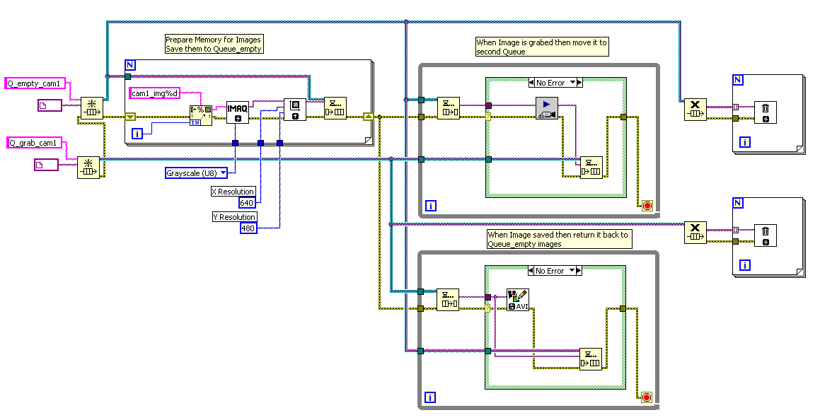
queues the IMAQ image data type
I'm trying to run multiple queues in the same loop entering IMAQdx images from several cameras, and then save to AVI. After reading the site nor a little, I discovered that the reason why I get only the last image of each bucket, repeated on all frames in the AVI file, is that the IMAQ image data type stores only the memory location for the image, not the image itself data. However, I don't see a better solution for the queues of the actual image data. What conversion could be the fastest / are in charge of the processor the lowest?

For each image you must initial Image space.
You can use something like this:
You need to add initialization camera (s) and AVI. You must add the multicamera feature. Stop recording is missing.
!!! Don't forget to throw lines and Images!
-
ImgBayerColorDecode of NOR-IMAQ to produce 64-bit RGB images?
According to reference Help feature, imgBayerColorDecode can be called with a void * pointer source and destination, so in principle it should be able to handle Bayer encoded images to 16 bits per pixel, right?
However, when I look at this old net, it seems that it is not possible, because only 32-bit RGB can be taken out. When I look at the "Bayer Color Decode.vi IMAQ" on our system, the dll call is one of:
"int32_t imgBayerColorDecode (int32_t dst, int32_t CBC, lines uint32_t, CLO uint32_t, int32_t dstRowPixels, int32_t srcRowPixels, const uint32_t * redGain, const uint32_t * greenGain, const uint32_t * blueGain, uint8_t bayerPattern, int32_t bitDepth, uint32_t reserved);
But settings can be changed apparently. So my guess is that imgBayerColorDecode can now convert 16 bit Bayer coded images in RGB (A) 48-bit or 64-bit images (+ alpha), but I can't find any mention of this in the page "What's new with NOR-IMAQ".
Can someone from OR Please confirm that it is possible today or is the old NET still valid?
Hi Oliver,.
During the period of SP1 2012, new Bayer decoding support added to the Vision. Bayer functions exported from the DLL IMAQ are discouraged because they don't have any of the new features. The functions are now in the Vision, but I think they do not need a license of the Vision Development Module (they are part of the basic API).
The new functions of Bayer are significantly faster, have many algorithms of quality varying and support the conversion of > 8 bit to RGB64.
imaqBayerToRGB() is what you should look into nivision.h.
Eric
-
How to use IMAQ detected Shapes.vi
Hi all
I learn NI Vision, I don't understand how to use IMAQ detected Shapes.vi to detect shapes, such as lines, ellipses, who can give me an example, thank you.
Hello
This function uses the edges of the object and try to adapt with different shapes such as rectangles, lines, or some cirles.
First of all, you need to set parameters to extract the edges of your objects. You Brown the threshold (in order to find the correct edges of your object). You can then choose the parameters of the shape to fit. For example if you want to adjust with a circle, you set the min and max possible RADIUS.
Try this with vision assistant, it will be easier. And try also with fine contrasting images.
Concerning
Maybe you are looking for
-
Satellite U400: touchpad stopped working after Vista update
Hello My Touchpad U400 cannot work after the upgrade, (under the Vsita system).I tried so many ways to solve, but still does notDid someone get hurt it? I tried to get into the BIOS to enableAnd also tried to download my touchpad driver (but I can fi
-
Faced with the installation of XP SP3 and XP SP2 on HP mini 210
Hello I followed the steps on my computer, HP mini 210, which was completely unusable: (1) Mini Partition Master tool used to boot the system. (2) remove all partitions, including HP recovery and everything. (3) create a new primary partition NTFS an
-
STOP: 0X000000ED (0X86D5C030, 0XC0000006, 0X00000000, 0X00000000)
My niece has a netbook that it turns off in the middle of the Windows form with the flag and the blue line "forced" down while he was starting the system. Now, he's not going beyond the start menu. I tried every method of starting, including disabl
-
We have just received the all in one printer 3050 wireless. The sole purpose of print from my iPhone. We do not have a computer at home. My husband has a work he sometimes brings home laptop. I figured out how to print in black only using his compute
-
Additional installation of hard drives... help!
My HP Pavilion D4100E has an internal hard drive bay that can accommodate two additional internal drives, but I can only find a housing of additional interface on the motherboard. Am I missing something? Are there other places in the interface that I