IMAQ several Kings
Hi all
I am trying to create a program that allows the user to draw a series of Kings (lines and rectangles) on a sample image, and then generate histograms etc for each of the Kings drawn and line profiles. I know that you can use CTRL + mouse down to draw several Kings, but my question is in each of these KING (descriptors) store in a table and then re-use of each collection of pixels for the analysis.
I managed to find a code here which starts quite close to what I have to do: http://forums.ni.com/t5/LabVIEW/Multiple-ROIs/m-p/1830029/highlight/true#M626558
Thanks TiTou!
So far, I have the code for TiTou (attached) and I was playing with separate Kings. I think my question is how exactly to use the descriptors of KING - how to use the table of them to find each line profile?
If someone can give me some pointers that would be much appreciated
Laura
Here is how I used several Kings in the past...
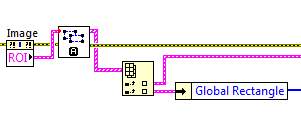
Each KING has its place in the table that is being indexed. (as well as two Kings in this example)
Tags: NI Software
Similar Questions
-
Select several Kings and set the properties for each of them
Hi all
I am currently working on a project on the thermal camera images. What I have to do is to define multiple regions of interest and assign specific properties such as temperature and emissivity of these Kings.
So I was wondering:
1 that is, possible to select several kings with a table keeping up-to-date of the Kings, the user has chosen on the front? (Or each KING might have a cluster on the front panel that contains its properties, which can be changed later.)
2. is that possible to set specific properties such as temperature in the specfic KING, these properties and will be updated for the return on investment?
Thank you so much and looking forward to some good ideas or tips.
See you soon,.
Version
Hi all
The attachment is what I've done now. However, instead create a .txt file to display information, it would be perfect to display the name of the KING and its properties in Control Panel before, as in the first column is 1 KING, KING 2, 3 return on investment, etc, and the other columns will be responsible for some information on the return on specific investment and its properties... Because I couldn't find something similar here, I really need your help.
Thank you
Version
-
Hello
I found the "imaq create King vi" and its good for what I want to do, but I have a problem.
In Control Panel, you can set only one KING. But I want to create many Kings (lines) on the same image of King cunstructor to make me a table of coordinates "line".
Can you help me?
Thank you.
Holding the CTRL key while drawing of your lines should do the trick.
-
Several kings with several clamps
Hello, I'm playing with the pliers to various VI in Labview 2011 and I have 1 working, but I want to have more than 1 (probably 3).
I already know about CTRL to make a new KING, but I have no idea how to do to send this information in the clip-VI, and then how to have all necklaces to see the square on the same image. In my research, I saw people use Group/dissociate from the Kings, also for loops to the index through the KING, but I couldn't get this to work with a pair of pliers.
I've attached what I have so far. Any advice would be great, thanks.
Please find the attached VI, I changed a bit the same code hope it serve and let me know if you need help.
Concerning
@sk
-
Error 1074395720 has occurred to IMAQ find circular Edge 3 IMAQ Vision: invalid KING.
Hello
I am writing a program to adapt to a circle of an image (from the avi), but when running the IMAQ find circular edge v3.vi I get the error message:
"Error 1074395720 occurred at IMAQ find circular Edge 3.
Possible reasons
IMAQ Vision: Invalid KING. "
I use the vi KING of construct IMAQ to set the return on investment and I am sure that the KING output is in a format suitable for the discovery of the IMAQ circular edge v3 vi.
I joined my program (Labview 2011)
Any thoughts?
Thank you very much
Rory
Hi Rory,
Welcome to the Forums of NOR.
«IMAQ find circular Edge 3' expects a return on investment for type 'Ring'.» There are a number of functions in labVIEW for the conversion of the type of return on investment as "IMAQ convert the KING to ring. However, as the circular edge VI find JUST does not ring but bounding box and other details as well, there is a strange solution to this problem.
Drop-down "IMAQ convert KING ring" and get the return on investment through. Drop-down and then "Convert ring to the KING" (Yes, really) and pass the output of who to "find the circular edge.
It is circular, strange workaround, but it seems to force the type of return on investment to go to the ring and so works.
Let me know if you have any other questions.
Thank you very much
-
Remove a KING chosen by the user
Hello
I have an application with several Kings generated automatically from an electrical CAD file. The user must inspect the result of creating automated Kings and possibly add or remove from a KING or more. Adding a return on investment was not a problem, it's pretty old the CTRL key. More difficult is to remove one KING chosen by the user. By now, I had to try to use the last test of the EEG control imaq, extract the coordinates and comparing it with the overall of the Kings rectangle, if I find a KING who coordinates the global rectangle are equal to the coordinates of the last round of get GET calls node I remove the return on investment. Problem is that sometimes, in so doing, I delete more than one KING, and sometimes I can't remove the ROI selected.I think that it is a trivial problem of the structure of control imaq, I searched in the forum, so I ask if someone found a procedure to do this.
Thank you very much, Francesco.
Hello
If you draw your KING on the image directly, why don't you also clear the same way? Click with the right button on the relevant KING outline and select 'delete the outline KING '. This will remove only the selected ROI.
Best regards
K
-
Hi guys,.
Part of my current LabVIEW project involves me using a video stream, and the user will have to draw several Kings on the power supply.
I would like to be able to allow the user to use an interface buttons to control the creation and the removal of the Kings, as opposed to the rather rough "n" ready approach "hold the key ctrl + click. Ideally, I'd like there to be a button display 'Create KING' that will create a ROI (rectangular) image, which the user can then move and resize as they see fit. I would also like an option 'Remove the KING', where the user will specify (perhaps from a drop-down menu) what return on investment that you want to remove.
I think that this can be done using property nodes, but impossible to achieve real progress on this. How should I go about this?
Thank you
David -
Several return on investment of the same size
Hi everyone again. I have questions about the plan KING
1. they say that you can make several KING by clicking the ctrl button and it works. You can make several KING out of it.
Question: a. how you can extract one of each KING?
b. are extracts KING represented by a table of coordinates or coordinates cluster?
c. is there a such that any part VI of the KING will have the same size and resolution) without resizing the return on investment)?
d. can you get a return on investment and use the size of this KING as the size of the next KING?
example: I did a 10 x 10 pixel KING in the first sample, the next King, a box of 10 x 10 will come out just so all I have to do is to move the box to the desired region.
PS maybe the same problem is already posted so I hope you can post the link of the subject then it is easy for me to find once again.
Thanks again for all the help I receive.
BREIN
A BEGINNER OF LABVIEW
Hello Brein,
1. Yes, the Kings are stored in the form of clusters, and you can extract all the information from KING using the description of KING.
2. you can save description of RIO in the cluster, then reuse them in your program. Here is a link to an example of use of the event structure to display pre-determined KING.
-
How to set up several areas of interest to IMAQdx?
I was always using Measurement & Automation Explorer for the region of interest (ROI). I would like to know if there is a way to set up two Kings for the IMAQdx, since I only need these two regions and they are on the left and right of the image.
Hey Ishi,
What camera do you use? FireWire and GigE Vision? Are wanting you the camera acquire several Kings simultaneously or you just want to go between them? If this is the first, while some cameras support this, there is no mechanism normalized in the standard for a bus I know for the camera to send several Kings of an image. Cameras that do this have their own mechanisms owners set up and decode the multiple images of the single stream. You must decode the image data manually do this with IMAQdx.
Eric
-
IMAQ Rectangle overlay problem
Hello
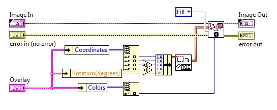
I'm trying to superimpose Roteted rectangle and fill inside.
I can't do it by IMAQ Overlay Rectangle - it does not accept the rotations
So I have PV Restangle of KING and I use IMAQ Overlay KING but now I have no fill option

You know the way to get around this?
Dear Pawhan!
As far as I know, you can have overlays of Rectangle rotated in Vision Assistant, you can create a to GO and create a LabVIEW VI from there. If you want to stick with the Vision of LV, try this code:
Please tell me if it works for you.
Best regards:
Andrew Valko
NOR Hungary
-
Hello Experts!
I have a simple question.
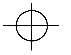
Is there a way, of creating user defined KING?
For example, I want to create a return on investment, such as:
Hello
Yes and no. You can combine this KING of three kings of base: two lines and a circle (or ring). Movement will be a little tricky (because all three kings should be moved together with the movement of the mouse) - you need to do programmatically. ("Point of departure") example as an attachment. Think otherwise maybe twice - it will be easier to use single point KING with overlay instead of several Kings.
Andrey.
-
Ring controls to create the visible circle
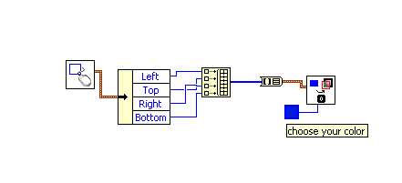
I try to use the ring on the front panel control to specify a circle with a radius of particuly pixel, and I'd like to be able to drag the circle around different x / Y positions. I was able to do, but the problem is, I don't see where the annular space is located on my image (the controls of the annular space do not give the corresponding circle anywhere) - there is no visual, just output text feedback in control boxes. Otherwise, I was able to create a circle on top of my image which acts as a region of interest using the KING property on the property node. The problem here is that I can not specify the RADIUS in pixels of the circle I draw my image above.
So basically I want to display a circle on top of my picture showing the return on investment and I want to be able to control the radius around an area of controls.
Jessica
Hello, Jessica,.
You can use the ring to convert IMAQ VI KING and the Overlay IMAQ KING VI to do this. The IMAQ convert Annulus VI takes a command input through which you can specify the RADIUS, X, Y and angles of the annulus. After that, the Overlay IMAQ KING VI will let you see the annular space displayed in the control to display the images. I hope this helps.
-
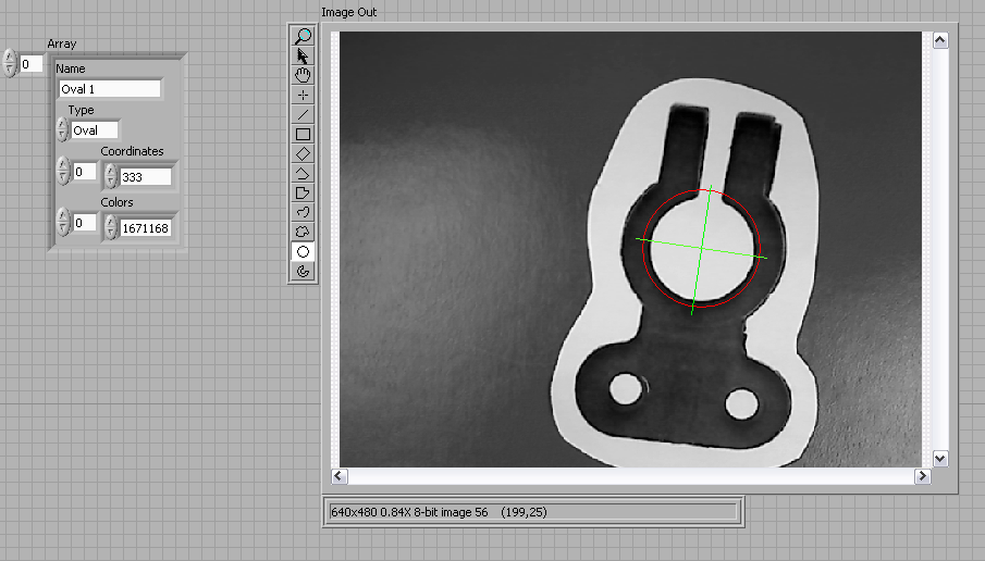
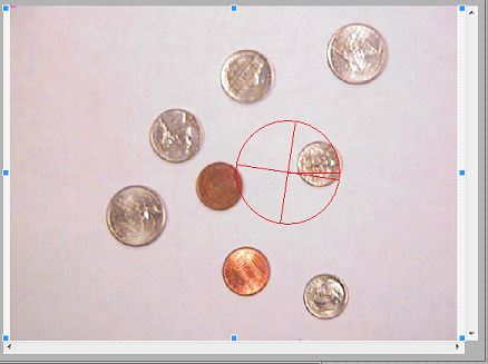
Return on investment with known constants
Hello
I am very new with vision dev module. Can someone help me please.
I have this vi that I want to work with the sample.
I was normally the OVERLAY of the image and draw the oval/lines on the image.
But I want to draw on the image, but he shoots in the return on investment so that I'm going to save memory?
With the oval contstants and lines in the CONTROL ARRAY.
Can someone help me by showing me in the diagrams, how would implement that using the KING?
Thank you very much.
Hey krispiekream,
I took a look at your code and made a few minor changes. When you use the ring to convert IMAQ VI KING data types don't align completely with the oval that you created. In the current configuration, you can do a little math to convert the coordinates of your lines to find the contact information of your ring. You can also add a little math for what I've done here to set up the corner of the ring and the size of the ring. An alternative is to manually create an oval ROI. This would require a bit of manipulation of data type, but it could be done. Take a look at the code, and the attached picture.
-
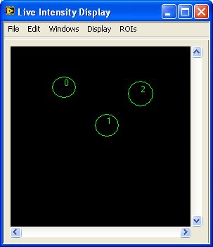
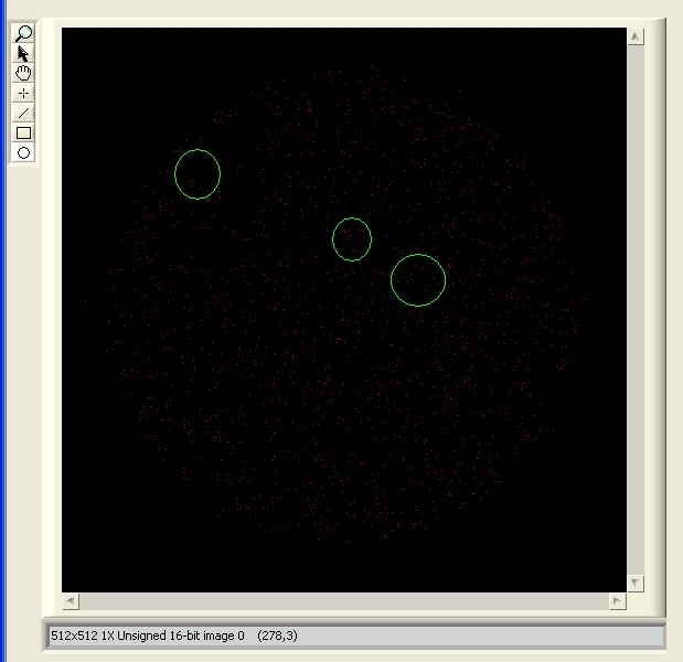
LabVIEW 2009 SP1 image ROI identification number?
In BT 8.5 (Vision), several Kings had displayed beside them identification numbers:
Apparently not so much more in 2009 SP1:
The only difference between the two screws is that I used a classic image object and I am now using the modern version; and the image tool window is replaced by the image associated with the picture tool palette. There is no property of the image I can find to activate the return on investment 'Legends' or not.
How the user is supposed to know what return on investment is that?
Oops...:
 indeed. I checked my LV 8.5 code (actually written in BT 6 or whenever the first control of the Image has been released) and I overlay numbers KING myself right here!
Given that I had used at the same time of overlay to get return on investment numbers, I've just reinvented the wheel... twice.
I still think it would make sense to access this feature by default in the Vision Toolkit.
X.
-
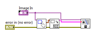
Strange problem with the KING and IMAQ find right 3 edges
So first of all, I noticed that the KING produced by KING features seems to have an incompatibility with the entrance to find right IMAQ 3 edges:
In my code, I have the strange problem "IMAQ find right edges 3" is the production of edges that lie outside the limits by the wired KING specifided: "."
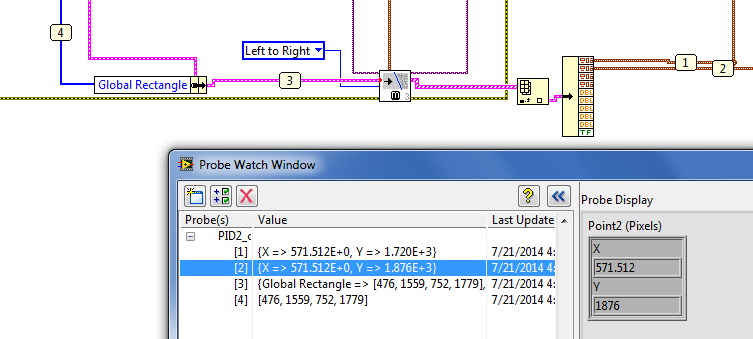
In this case, a return on investment, defined by a rectangle, I [476, 1559, 752, 1779], but the best line produced by VI shape is outside this rectangle (see ordered 1876).
How is that possible?
I finally thought to it - it was my fault. I was updating the global rectangle in the KING entered correctly, but not the contours.
I fixed the wiring and now it works fine.
Detective Conan!
G
Maybe you are looking for
-
Photos opens is no longer since the update of El Capitan 10.11.5
Please can anyone help how can I solve this problem since update to El Capitan 10.11.5 pictures won't open and gives this error I tried see if there is an update but it is not a downloadable and I dare not remove it because you don't seem to be able
-
Wiring of the AC source single-phase NI 9225
Hi all How can I wire an AC single-phase my point of wall to the module OR 9225. Agrees that if I connect LIVE wire wire HAVE + and I - NEUTRAL wire? Thank you Ajay.
-
SMS & journal of the 8100 smartphone flashing white, clear call blackBerry
I have the 8100 and just recently, whenever I have unlock my keyboard, the screen flashes white and deletes my call log & all of my text messages. Really annoying, if I miss a call there is no newspaper when I check. I've had my Pearl for a year no
-
Had to reboot the computer because of a virus and now only have a trial version?
I bought windows 7 Home premium online, installed it about 6 months back, but meanwhile, I got a virus and had to reset my windows 7, however I do turn on a trial and do not have the product key on a cd, because I did it online... Is there anyway tha
-
Windows Narrator in other languages (different from English)
I recently updated my windows from 8 to 8.1 in the previous version, I could make a choice between Spanish, French or English voice for the Narrator windows (accessibility), but now I just has the English and the voice, the question is: is there any