Interruptions FPGA: buffering?
Hi all.
When using FPGA for RT (IRQ) host breaks, it is buffered then?
Say that the FPGA does not expect the host to recognize the IRQ. Then the FPGA can send traps multiple host, if the host loop runs more slowly than the FPGA loop for a while.
Will be the host received all send interruptions, or only the last?
A.E.P wrote:
I see 3 solutions to this problem:
(1) if the interruption is buffered, the host of RT would receive just any interruptions to the level that the RT host can manage. This seems not to be an option.
(2) make sure that the FPGA expects host RT to recognize interruptions before continuing.
(3) the FPGA can send aditional interrupts every 500ms (or almost), then RT host can check if DMA contains all the data.
The fourth option is to have just read RT all packages that are in the DMA, whenever it gets to it. You could then treat in a loop FOR.
Tags: NI Software
Similar Questions
-
the videos that I watch are constantly interrupted by the buffering
Original title: video buffering
The videos that I watch are constantly interrupted by buffering. How can I watch videos without interruption?
Hello
Here are some links to try to solve this problem:
http://www.webcastingzone.com/webcasting-articles/video-streaming-problems.php
http://www.delete-computer-history.com/slow-streaming-video.html
B Eddie -
Typical time a request for interruption takes between RT LV and LV FPGA.
Currently, I don't have the equipment to test it, and I was looking for some statistics calendar all the time it takes for a request for interruption to process between LV RT and FPGA LV (LV RT generate the interrupt request, waiting LV RT on ack, LV FPGA get query pause and LV FPGA ack, LV RT continue). I know that the interrupt request has a priority higher loop timed on LV RT, and a concern for this issue, let me say that the FPGA LV does not what whatsoever between the receipt of the interrupt request and receipt.
Does anyone have any time?
Hello Michel_Gauvin,
I found the following article in the knowledge base that may answer your questions:
Landmarks of Module time real LabVIEW for Applications in the LabVIEW FPGA Module
I hope this helps!
Kind regards
-
I'm watching a show, but I keep getting interruptions while it is buffering
I'm watching a show on my computer but it keeps cutting and buffering, then he runs again. Can you tell me if I can change something in the settings that will allow me to attend a show without it cutting all the time
Hi Charpaul,
The buffering is caused by your internet connection. Even if you have a relatively high speed of internet connection, your ISP reduced as people more open a session. The more bandwidth use you the slower things can get. If you get to watch both occupied day or night then your PC will be buffering of the data on a regular basis. It is one of the reasons why I don't watch TV on internet, at the moment where you buffering caught up with, unfortunately, lost the plot of what you were watching. A way around the problem is to try to look at where the internet is not so busy - in my case around 02:00. John Barnett MVP: Windows XP Expert associated with: Windows Desktop Experience: Web: http://www.winuser.co.uk ; Web: http://xphelpandsupport.mvps.org ; Web: http://vistasupport.mvps.org ; Web: http://www.silversurfer-guide.com
-
Synchronization of multiple FPGA PID loops
Hello
I am the design of a PID controller for each of the three axes (X, Y and Z) of a piezoelectric stage using the FPGA module and a cRIO. I used the example of project "Using Discrete PID - cRIO.lvproj" (labview\examples\control\pid\fpga.llb\CompactRIO) as a starting point and I've basically added two PID loops more on the FPGA VIs to the other two axes. I can get the controller to work for an axis at the same time (in simulation mode), but whenever I try to run all three controllers simultaneously, only one works. In order to synchronize between the host and the FPGA VIs, I used three interruptions for each PID loops, but it seems that a single interruption works when I run the code... No idea how to synchronize the three loops of PID with the host VI?
Kind regards
Shin
I think that it is an expected behavior, by the documentation: "VI the interruption is a shared resource, so multiple uses of it induce a further delay and jitter due to arbitration." If you are waiting for the interruption to see, then the other loops cannot continue because interruption VI does not work. On the FPGA if you want all the PIDs to operate at the same speed of loop, put them all in the same loop and use only a single interruption. Or use another synchronization mechanism (set to a boolean of the host, wait it is defined and then erase it on the FPGA). The interruption is only for purposes of simulation, in any case, since the 'central' is running on the host computer. In a real system, the plant works continuously and FPGA directly reads the sensors and outputs, the readers so the only value provided by the host is the set point and is not required for synchronization.
-
My program has normally run this afternoon, but after I saved the new file (seems no change), I can no longer see the wave in the wave chart more at the launch of the vi of the host. Only when I keep the FPGA vi running can the wave be displayed on the chart. I don't understand what happened. I used Run like the invode method but I can't browse FPGA vi host more. Any help will be much appreciated. I've also attached the FPGA and host vi, which is barely changed from the examples.
You have no need to run it invoke the method as your open FPGA VI reference is currently configured to automatically run the VI. I recommend you either remove the invoke method or right-click of your FPGA VI reference open and change its options so that it is not automatically run.
The way you transfer your data between your FPGA and host VI could be the problem. Currently on your FPGA VI, you have a waveform chart and a function of bundle. As a general rule, you don't want no graphics on an FPGA VI front, since it is as just the low-level code do your FPGA-level tasks. Display you your data when you pass it to your host. In addition, there is no reason to combine a single item of data in a cluster, you can just do an indicator I16.
In addition, I do not understand the system calendar, maybe I'm just confused here. Your front panel for loop rate default configures the FPGA VI to enter a new sample of AI every 100uS. Which means the FPGA will be claiming a break 10,000 times per second. You have your host VI set up to wait for a break before the reading of the indicator, but the host is configured to run every 10ms, or 100 times per second. Basically you have your FPGA and your host VI running at different rates orders of magnitude, but try to synchronize the bed with an interruption.
You can run the FPGA and host screw at different rates with success using a FIFO of DMA or a queue, between them. Ensure your FPGA VI is grabbing samples very fast and packing in a queue, one both for the host VI to grab a chunk of at a slower interval. There is a great document on how to do it here: http://zone.ni.com/devzone/cda/tut/p/id/4534
-
What is the use of FPGAS and how it differs from the IO Modules
Hi all
Maybe it's a silly question for most of you. But I have very less knowledge about the basic concepts of electronic (FPGA, real-time) to cRIOs. I know that FPGA
can be used to generate circuits within the chip that helps by some logical functions.
I've just started working in the cRIO. My question is that we have Modules e/s making it outputs all the application entry. So, what is the purpose of e/s in the FPGA.
Lets consider that we entered for an application of RTD. In this case the module NI 9217 itself exits 24 bits of data from the RTD measurement which may be the process of the LabVIEW VI. What will be this FPGA between the i/o Modules and the processor will help in? Also I want to know what type of communication is used to send data between the FPGA and host modules.
Thanks in advance
Ajay HI:
Sorry, you do not have an answer to your original question. However, you are right about the benefits of the FPGA. You said, if you build pre-processing in the FPGA, you can unload a lot of potentially CPU calculations out of the host processor. In addition, the program running on the FPGA is highly deterministic and can run the code very quickly. So if you build a kind of guard or evanescent dog part of your application, the FPGA is a good place to put it.
To answer your other questions, communication between the modules and the FPGA is generally above the SPI and the data can be transferred between the FPGA and host via DMA FIFO operating on the PCI bus or single point save access using read/write in the FPGA host Interface controls. You can also use interruptions in signal of disputes between the FPGA host.
I hope this helps, but let us know if you have any other questions.
-
FPGA - windowed moving average, variance, standard deviation, kurtosis and asymmetry
Hello!
I'm processing in FPGA and I want to calculate the MOVING WINDOW average, variance, standard deviation, kurtosis, asymmetry online for the last N (N is the size of windows) elements. The frequency is about 100 kHz and N about 10000 (100 ms of signal).
I found something like EMA (moving average exponential)...
Have someone solved something like that? Any ideas how to fix?
That looks like a problem. What type of window you need? The moving average exponential isn't an option? There are online algorithms described in Wikipedia, but they can suffer from problems of numerical accuracy when it is implemented in a fixed point (depending on the nature of the data). They would be interesting watch in, however.
Other than that, here are some options that I can think of:
- More large FPGA
- Be part of the treatment on the RT controller - have - you looked into that?
- Return to your needs and push some of the numbers. Do you really need 100 ms in all cases, etc.?
- Depending on the nature of the data, simple compression techniques may be an option
- An precision analysis to determine the data type minimum, that you really need. For example, getting to 25 bits, would have a huge impact on your cost of multiplier.
- Consider the mathematics of floating (using Xilinx IP cores) point to online methods. Your flow is relatively low, so you could share it resources between all channels. Manage States of different channels is complicated but is doable.
The BRAM will be used for FIFO buffers, but is also available for general use to implement the fifo and memories. Some IP use BRAM under the hood, keep an eye on the compilation summaries to monitor how much still you have.
-
FIFO of DMA beteen switching channels after sends FPGA
Dear community,
I read 8 AI with the CRIO high frequency corresponding to 8 sine waves of resolvers. Also, I do operations in the FPGA and passing to the RT host 2 FIFOs. One is called resolvers with these 8 channels and the other is called speed and accel. who has 12 channels with 4 angular positions, 4 speeds and accelerations 4 in that order. When I read the two FIFO with the host I wait for the PEPS have enough elements. I also put the time-out of the FPGA-1 to avoid problems altought I know very well what to select. The problem is that when I read with the host, the channels do not keep the original order I used to assemble in the FPGA and also it is possible to appreciate swithings between channels every few seconds so that the information is not uniform and robust. It is not possible to use the information if the channels do not change their relative position.
I have ideas to solve this and incrementing the RT frequency because it goes to the maximum of 60 Hz, where I expected much more.
Thank you very much.
Concerning
Enrique
EnrikDS wrote:
Hello
attached are two images to explain what settings I use to configure FIFO. We can concentrate on speed FIFO:
-Depth confgured to: 120000
-Number of items in a read statement: 1200
The FIFO can also be configured in the Project Explorer, in fact, I'm not sure if the depth setting configured in the block diagram means the same as the parameter
"Asked number of items" that appears when you double-click in the FIFO to the Project Explorer, the value is 4095. Other values are:
-Target to the host
-Data type: FXP (64-bit, 32-bit)
I hope this helps. Thank you very much for your support.
Enrique
When you configure the FIFO since the project you define how much space FPGA to be used for the FIFO for buffering before data are duplicated in the FIFO of RAM defined by the property node.
Have you tried to set the expiration time of the FPGA FIFO entry to 0, that would be a FIFO with loss. You can use the FIFO. GetNumberofElementstoWrite to ask how much space is in the FIFO and write only when you have 8 to 12 free items.
-
How to choose the maximum number of items for DMA FIFO to the R series FPGA
Greetings!
I'm working on a project with card PCIe-7842R-R series FPGA of NOR. I use to achieve the fast data transfer target-to-host DMA FIFO. And to minimize overhead costs, I would make the size of the FIFO as large as possible. According to the manual, 7842R a 1728 KB (216KO) integrated block of RAM, 108 000 I16 FIFOs items available in theory (1 728 000 / 16). However the FPGA had compilation error when I asked this amount of items. I checked the manual and searched online but could not find the reason. Can someone please explain? And in general, what is the maximum size of the FIFO given the size of the block of RAM?
Thank you!
Hey iron_curtain,
You are right that the movement of large blocks of data can lead to a more efficient use of the bus, but it certainly isn't the most important factor here. Assuming of course that the FIFO on the FPGA is large enough to avoid overflowing, I expect the dominant factor to the size of reading on the host. In general, larger and reads as follows on the host drive to improve throughput, up to the speed of the bus. This is because as FIFO. Read is a relatively expensive operation software, so it is advantageous to fewer calls for the same amount of data.
Note that your call to the FIFO. Read the largest host buffer should be. Depending on your application, you may be several times larger than the size of reading. You can set the size of the buffer with the FIFO. Configure the node.
http://zone.NI.com/reference/en-XX/help/371599H-01/lvfpgaconcepts/fpga_dma_how_it_works/ explains the different buffers involved. It is important to note that the DMA engine moves data asynchronously read/write on the host nodes and FPGAs.
Let me know if you have any questions about all of this.
Sebastian
-
How to handle interruptions in SMU-6363
Hello
I'm working on a PXI tester to test the ASICs. I use in the tester, SMU-6363 map and module SPI NI USB-8452 to speak to ASIC chips. The ASIC chip sends a signal of interruption to the SMU-6363 when its finished with a certain measure, for example. a measure of tension of ADC. On receipt of this signal of interruption of the ASIC, the tester PXI running LabVIEW must obtain measured value through SPI (NI 8452) to ASIC.
I have the following questions regarding this set upward:
1. can I connect the signal interruption of ASIC to any PFI on SMU-6363 line so that in case of the impulse of the interruption, the tester can meet this interruption by launching SPI Comm by nor-8452 module?
2. If so, how can I make a coding in LabVIEW to meet this impulse interruption PFI online?
Thank you
Jeet
Hi Jeet,
You see error-201062? By changing the default value of detection tasks are buffered, and it is only supported by port 0. To make it work on all ports on your device in the X series, you'll want to add an entry DAQmx Configure Buffer.vi and explicitly set the size of the buffer to zero. I have re-attached my VI example with this change.
Hope that helps,
Dan
-
Safe multithreading NI FPGA Interface C API?
Hello
I use the FPGA C API interface to communicate with the software labview on my FPGA OR. Some calls take a while to run, for example, reading on a FIFO so long timeout. So far, I assumed that the interface was not safe multithreading. It has now become annoying given the timeout problem described above. Try simply was not good, it can take a long time to create a "collison.
Is the FPGA interface safe multithreading C API? Or, more specifically, the functions of FIFO reading can be called in parallel with read/write variables on the FPGA?
Thank you.
Hello MKAP,.
It has been a while since I used the NI FPGA Interface C API, but it is what I remember and seem to be able to remember (and also found in the documentation):
Functions related to the unloading and loading of the library are not thread-safe:
http://zone.NI.com/reference/en-XX/help/372928D-01/CAPI/functions_required/
On itself, this should be a problem:
Your application should require that the NiFpga_Initialize is called before any other function associated with function calls NIFpga.
In a similar way that unloading (NiFpga_Initialize) lof NiFpga brary should occur only when you are finished using it.
With regard to multithreading, you must also keep in mind its mono-thread interrupts IRQ (if you plan to use them):
http://zone.NI.com/reference/en-XX/help/372928D-01/CAPI/functions_interrupt/
-
FPGA SIT VI disturb application feature!
Dear Sir/Madam,
I have a question about FPGA combined with the Simulation Interface Toolkit and I will be happy if you could give me some advice!
I have a HiL application that is based on the following:
-Host VI on Windows PC.
-VI driver on the system in time real VxWorks on CompactRIO 9014.
-VI FPGA, which contains 2 nodes of e/s which I use to swap frames with an external CAN CAN network to control a machine'S FPGA-VI-controls that represent the different channels of the Messages CAN get their signals through FPGA mappings that I set with the SIT connection manager.
My problem is how to get the best time for the FPGA VI to synchronize it with the driver VI. The default method, I get the model comes from the interruptions. Although my FPGA target 9104 supports interruptions, when I run the Application and after the deployment of all the screws on the cRIO target, the simulation stops and I get an error: (see attached screenshot).
I wonder why the request could not be started when it is connected with an external CAN network, because when I tested it with a cable loop (I connected CAN 0 with 1 CAN leave the Modul NI 9853 CAN with a CAN cable), it worked without problem.
So I will be grateful if you could explain to me how can I change the FPGA VI or VI driver to get their work together!
I have also attached my FPGA VI.
Thank you in advance!
--
Yours sincerely,
Mehdi MeddebDetails of software zur: LabVIEW FPGA 2009 version
Material: RIO (cRIO, series R, FlexRIO, sbRIO) device CRIO-9014, NI 9853 CAN
Driver version: NI RIO 3.2
Operating system: Windows XPHello Andreas,
Thank you very much for your answer!
The problem was exactly what you explained! I wonder why the default value of the timeout is so great!
Fortunately, I found the solution for a week, and given that the application works well!
A big thank you once again and I look forward to hearing from you soon!
-
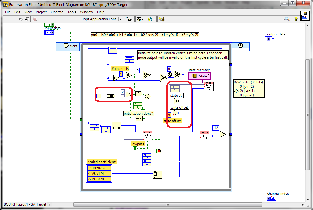
FPGA Butterworth filter - why conversions to decimal fixed?
I was looking through the screw FPGA Butterworth filter Express and stumbled on this code (after conversion the Express VI into a Subvi and then by opening the front panel):
What is happening with the conversion to decimal fixed values that look like they must be integers (in the red boxes)? Why these conversions would be useful?
Here is the micro-optimisations to help the synthesis tools to minimize the number of bits used in these code paths. The iteration Terminal is 32 bits wide and also involves a logic to do in the face of what is happening when the maximum value is reached. We have seen some benefits from the reduction of this path to the minimum width required both that which is written. I think it is probably still the case since the compiler usually does not know how many times a given line will run with a dynamic stop like this condition.
The optimization of the meter width is similar, taking advantage of the fact that we know that we have limited storage space to use circular buffers power-of-2 size. Using the exact number of bits of the address allows us to implement a counter of reversal with no additional logic. otherwise, we would need to check the value, and add a mux (Select) to reset the counter when it reaches the maximum value.
Synthesis tools usually do a good job of optimizing the unused bits, but here are two cases where we can help them by being more explicit about what we really need.
-
How to run two 'County of buffered edge' using two different counters at the same time?
Hello
I try to use two counters at the same time count the TTL pulses for a fixed period (lets say 10 ms). I have the card PCI-6251 and PCI-6601. I am currently using PCI 6601 as counters and running a self updated the ' stamped edge County - reset.VI. Here, I have attached my VI.
Now, during the execution of this VI, I get an error saying "error-200251 occurred at Task.vi:4 DAQmx Start" and the possible reasons are, "measures: no USB or DMA channels in loose ends are available.»
Either stop other tasks which might be using these resources or are considering changing your mechanism for transfer of data to the interruptions if supported.
Device: Dev2
Task name: _unnamedTask<80>. »
What I realized is I'm trying to use two buffers for two meters with ten samples each and this is probably not allowed. I don't know how to solve this out and bad looking for your suggestions.
Thanks in advance.
Hi all
I found a solution too. This is the VI updated the "County of edge stamped" which can simultaneously run two entries-meter using a single source of door and it also uses the DMA and interrupts to save two pads.

Have a nice weekend.
Maybe you are looking for
-
10 with Bootcamp Windows Bluetooth driver
Hello I have an iMac 27' end 2012, running El Capitan. I recently installed 10 Windows on Bootcamp, and everything went well. Except for one thing: No matter what I do, I can't get the bluetooth running module. Specifically, its called "Bluetooth USB
-
A6210 not detected and no led light
Hello! I have a problem with my adapter wifi and id as a solution, basically when I got my netgear upgrade wasn't my thing more it was not detected, I tried on my brothers computer and also, it did not work. I don't know if it's the software or the h
-
HP pavilion 2006sq g6: 1 TB Hard drive 7200 RPM for g6 2006sq pavilion
Hello I am planing to buy a new hard drive for my laptop because my current is on alert I found this one: HGST Travelstar 7 K 1000 1 TB, SATA-III, 7200 RPM, cache 32 MB, 9.5 mm http://www.Newegg.com/product/product.aspx?item=9SIA2W02KN0922 and wanted
-
My time of activity Notebook G62X-400
My laptop turns off if I relax for a while and I have to move the mouse to back up page again, or I have to log in again. Here for page stay in place longer.
-
I lost most of the events of the calendar after syncing with my phone. How can I get it back?
Hi, I synced my calendar windows (vista)) with my HTC phone, but I lost most of my calendar events in my computer. How can I get it back