L3 Nexus 7000 routing Proxy
Hello
I propose Nexsu 7000 as backbone switch for my client.
But I do not understand why proxy L3 routing must be used under M & F2 mixed condition.
But module F2 also bear all capacity of L3, L3 routing dosen't support of the F2 module with module of the M series.
Could you tell me why this is happening and explain Nexus 7000 architecture?
Thank you
Yun.
M2 + F2e in same VDC works dated 6.2 (2), in which case F2e module returns to the classic transmission L2 mode, leaving all L3 decisions up to the M2 module, so you still need L3 routing proxy.
I think the reasoning behind this is because of the motor M2 L3 being much more potent than the freight forwarder F2e L3. For example, the motor M2 can make OTV, the impossible F2e. Logic to return L3 decisions for a more powerful card.
What I find strange is that although F2e online map has an integrated transmission of L3 engine, that I can not configure the IP of L3 addresses directly on F2e ports. Creating a VLAN SVI and by setting the port access mode F2e work, but if I only need a link point single point of L3 between the Nexus 7 K and another device, and I have configured the vPC, vPC then in an inconsistent with Type 2 State, because the VLAN and/or IVR is not present on the switch of peers.
Tags: Cisco Support
Similar Questions
-
We have 2 core witches nexus 7000 and then downstream to 2 nexus 2000 is.
then e have 6248up fi for the UCS. should he go to the nexus 2000 or directly at the base of 7000 nexus?
What is the benefit or to the detriment of go to the nexus 2000 or 7000?
You must join the Nexus 7000 6248.
Nexus 2000 was created to connect to end-hosts and not the switches or the FI. Since all local switching is performed on N7k, if you connect FI N2k, ensuring the same between the blades will be sent through n2k to N7k, tissue link N2k - N7K will be oversubscribed and UCS will suffer poor performance.
So FI must be connected to the N7K
HTH,
Alex
-
Nexus 7000 - integrate FEX - identify ID ASIC
Hi *.
in reference to this the following guide, I would like to identify the Asic-ID, to plan the integration of a FEX 2248PQ to an interexploité in a context of F2e M1-xl-type F2 module.
There is a note in the section "combining of a tissue Expander to a Module of the F2 series.
Each port in the ASIC has an index. Allow only ports with similar indices across ASICs to be added to a port channel.
For example, if port 1 has an index of 1 and port 2 has an index of 2, the following ports are supported and not supported:
- Support: 1 1 ASIC and port 1 of 2 ASIC are added to a port channel.
- Unsupported: Port 1 of 1 ASIC and port 2 2 ASIC to form a port channel.
A set of ports to an ASIC that a set S, such as {1,2,4} Sub index, is authorized to add to a channel of port if the port channel has an equivalent, or an empty set.
So is there a way to get the asic-id, as mentioned above, with a few appropriate show commands?
Please be advised that the FEX are not yet installed.
I need to check beforehand if the wiring is correct.
Some useful answers in the next a few would be very much appreciated.
Thanks in advance
Sven
Sven
Take a look at this article, and if all goes well he will answer your questions.
http://www.netcraftsmen.NET/blogs/entry/using-FEX-with-the-F2-card-in-a-Nexus-7000.html
Jon
-
Nexus 7000 questions sampled NetFlow
We have Nexus 7000 s set to sampled netflow. We have tools which have reconstitute recording of flows sampled for the management screens. Most of the tools require the template folder of feeds, optionally and to send in order to reconstruct the sampled flow record. We've captured some of this traffic and noticed that the template contains "SamplerMode": unknown (1) [see Nexus 1 - 1.png]. Is this normal or have we do not include the commands needed for the operation?
Thank you
Terrence
fearure netflow
Active Stream timeout 60
flow timer 15 inactive (default)
workflow session
threshold flow timeout agreesive 80
workflow exporter flow_exporter
x.x.x.x use-vrf destinations management
9996 udp transport
version 9
the 30 model data timeout
exporter-stats 30 timeout option
option table sampler timeout 60
flow flow_record record
match source ipv4 address
! {many instructions}
netflow_sampler-2 sampler
out of 1 100 mode
Flow monitor flow_monitor
record flow_record
exporter flow_exporter
interface VLAN 150
IP flow monitor output flow_monitor netflow_sampler-2 sampler
Hello Terrence,
You are right about "most of the tools require registration of flow, the option and the model" and they also require the definitions of all elements used for export.
We maintain constant communication with Cisco for their last item ID and definitions (e.g., description, type, length, etc.). It looks like your collector may need definitions. Once updated, the front-end server must then be updated to make use of the new element if you want to use.
If you send a capture of packets of the flow to Plixer will give you a more complete diagnosis. Make sure you include the models.
You can vote if my post answered your question.
-
Hello
Could you explain the following paragraph, located at the following ADDRESS:
«In some circumstances, you might consider having a distinct link between both vPC switches, to form the layer 3 Protocol Routing peering or transport traffic VLAN no - vPC.» * While this design is compatible with the Cisco Nexus 7000 Series switch, it does not work on the Cisco Nexus 5000 series switch *. With the Cisco Nexus 5000 Series switch, we recommend using a link of vPC for Layer 3 peering peers in order to perform the vPC and non - vPC VLAN. »
I have deployments of Nexus 5 k with L3 cards which have separate links for L3 and no vpc VLAN instead of having them on the link of peers VPC and they seem to work well. This is a mistake in the documentation or could I have problems?
Thank you
Eric Lauriault, CCIE 27521
Hi Eric,.
In the URL you have specified http://www.cisco.com/c/en/us/td/docs/switches/datacenter/nexus5000/sw/operations/n5k_L3_w_vpc_5500platform.html
Take a look at Figure 3-10 and now add another layer 3 linking N5K N5K-1-2.
1 multicast is sent on N5K - 1
2. multicast routing on N5K - 1. A copy is sent to the interface of L3 and another copy is sent to the peer-link in vlan reserved (in the vpc bin - vrf default vlan xxxx).
3. the packet received on the interface of layer 3 multicasting will still get replicate by the peers-Link.
Thank you
-KL
-
ASA 5512 different route by VPN Group (VRF as feature?)
Hello
Here's what I'm trying to do. I have a Nexus 7000 with several of the VRF, simplicity lets call it A VRF, VRF B, VRF C. VRF A simulates a network of management and VRF B and C are customer environments. VRF B and C VRF will be overlap of intellectual property. I have a 5512 ASA I use VPN in the environment, it also provides internet access for applications that run in A VRF, (VRF B and C do not require internet access). What I want to do is to implement three different access VPN on the SAA even, where some users will have VPN 1 group policy and have access to the VRF has, but should not have access to the VRF B or C, same VPN 2 should have access to the VRF B and 3 C VRF VPN.
My original intent was to configure the ASA with 0/0 to internet Gig, Gig 0/1 A VRF and then Gig 0/2 sub interfaced so 0/2.10 is 10.10.10.1 in VLAN 101 that connects VRF B, 0/2.11 concert would be 10.10.10.1 in 102 VLAN that connects to VRF C. However, better than I can tell ASA 5512 is not aware of VRF (or is it just a separate license, I would need?) and as such, it is not possible.
Next similar reflection, but instad configure as 0/2.10 is 10.10.10.1 in VLAN 101 that connects VRF B, 0/2.11 concert would be 10.10.11.1 in 102 VLAN that connects to VRF C. However, I throw it here, issues as the VPN 2 and 3 need access to devices with the same IP address, which is even better I can tell, the ASA is not able to make Policy based routing.
Is there another way to do this? Is there something that I am on?
I need to make sure that the 2A VPN users can access services available in the VRF B, they should not have the ability to access (intentionally or not) services on VRF A or C, nor the users VPN 1 or 3.I have also a 5585 ASA w / context multi license, I can then creates a context by VRF (that I have), I then interfaces in each correct the VRF-related context. However, I do not think that I can terminate VPN here, best I can tell when in multi-contexte mode you can not have VPN license.
Your research led you to conclude correctly that the ASA is neither compatible with VRF nor can it be based on routing strategies. Also, you cannot terminate remote access VPN on an ASA multi-contexte.
Doing what you ask a single AAS is a bit problematic. If you had a unique internal addresses, the subinterfaces would work fine.
Because it looks like you have a virtualization infrastructure, have you considered using the low cost ASAv? You could run multiple instances, one per VRF. Everyone knows only the public address space and its respective assocated VRF.
-
I want to get the best on my router (Port Forward questions)
I use the WRT54G2 router and the wmp54G. I'm trying to get games like America's army and Team Fortress 2 to work properly. I've assigned my static Ip pc using the guide portforward. I forwarded the necessary ports.
I can't connect to my account on the U.S. military, and I can not connect to servers on Team Fortress 2. I tried to disable my anti-virus and firewall but still no luck. I'm doing it on the pc with the wireless connection.
Any suggestions?
I also have another question: when transmitting ports or using DMZ, what IP address I send? The pc connected directly to the router or the pc which is using ports (one wireless)?
BTW, MY ISP is Comcast
In most cases, you can use the DNS proxy server that is built into the router at 192.168.1.1 (address by default), but in your case would be in 192.168.2.1
It is preferable to use the DNS proxy server. The router keeps track of the actual Internet DNS server addresses from your ISP and transfers data to the appropriate DNS server.
If the DNS server of the router proxy does not work, then enter your true Internet DNS server address in your computer.
In addition, I see that you use the et.102 adresses.101 in your computers. Your range of DHCP servers by default est.100 thru.149, so unless you have changed it, you use illegal LAN IP fixed addresses in your computer. This could be the cause of your problems. Note that all fixed LAN IP addresses should be outside your range of DHCP server.
-
Can someone tell me what is the difference between F2 and new F2e? All I can find is supportive effect. Isn't it?
The biggest complaint (and Gotcha) when people bought the N7K-F248XP-25 (aka standard F2) is an inability of the online map to work with F1 and M1/M2 card. The F2 has be in it's own little VDC. No member of Cisco would have admitted that it was due to a technical fault (or disaster).
Thus the F2e is born. Whatever the standard F2 can do, the F2e can do as well. And the F2e can work with M1/M2. "And when that happens (as indicated on the data sheet)" when you deploy the Module Cisco Nexus 7000 F2e-series fiber has VCC with the Cisco Nexus 7000 M Series modules, the Nexus 7000 F2e - series Cisco Fiber Module will run in mode Layer 2 only, delegating all capabilities of layer 3 for the Cisco Nexus 7000 M-modules of the series present in the VDC. The initial version of the software does not support this feature. »
The F2e comes in two "forms": 1/10BaseTx 48-ports or SFP / SFP +.
As the "F2", the F2e still won't be able to support the OTV (integrating F2 series Modules in a Cisco Nexus 7000 Series System).
Due to the release of the new map of F2e expect Cisco to announce (within 6 months) at the end of sale of the standard map of F2. (My own opinion, read below for refutation of the management team Cisco Nexus 7000 Production.)
I don't know what Cisco will do to customers who bought the standard F2 by mistake. Cisco quietly will allow them to trade or swap for F2e? Only people (like Jerry) in Cisco will know.
Post edited by: Leo Laohoo
-
What does Nexus 1000v Version number Say
Can any body provide long Nexus 1000v version number, for example 5.2 (1) SV3 (1.15)
And what does SV mean in the version number.
Thank you
SV is the abbreviation of "Swiched VMware"
See below for a detailed explanation:
http://www.Cisco.com/c/en/us/about/Security-Center/iOS-NX-OS-reference-g...
The Cisco NX - OS dialing software
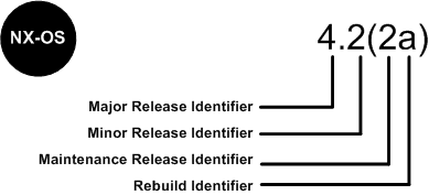
Software Cisco NX - OS is a data-center-class operating system that provides a high thanks to a modular design availability. The Cisco NX - OS software is software-based Cisco MDS 9000 SAN - OS and it supports the Cisco Nexus series switch Cisco MDS 9000 series multilayer. The Cisco NX - OS software contains a boot kick image and an image of the system, the two images contain an identifier of major version, minor version identifier and a maintenance release identifier, and they may also contain an identifier of reconstruction, which can also be referred to as a Patch to support. (See Figure 6).
Software NX - OS Cisco Nexus 7000 Series and MDS 9000 series switches use the numbering scheme that is illustrated in Figure 6.
Figure 6. Switches of the series Cisco IOS dial for Cisco Nexus 7000 and MDS 9000 NX - OS
For the other members of the family, software Cisco NX - OS uses a combination of systems independent of the platform and is dependent on the platform as shown in Figure 6a.
Figure 6 a. software Cisco IOS NX - OS numbering for the link between 4000 and 5000 Series and Nexus 1000 switches virtual
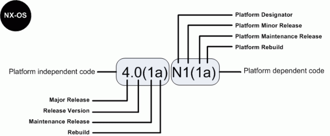
The indicator of the platform is N for switches of the 5000 series Nexus, E for the switches of the series 4000 Nexus and S for the Nexus 1000 series switches. In addition, Nexus 1000 virtual switch uses a designation of two letters platform where the second letter indicates the hypervisor vendor that the virtual switch is compatible with, for example V for VMware. Features there are patches in the platform-independent code and features are present in the version of the platform-dependent Figure 6 a above, there is place of bugs in the version of the software Cisco NX - OS 4.0(1a) are present in the version 4.0(1a) N1(1a).
-
After a recent deployment of the switch, I see some very strange transmission problems layer 2. I'm not sure if this is related to a problem of configuration on my part. I would like clarification on the VPC, and I hope you can help me.
It is my understanding that when you have a series of double-sided VPC between, say, a pair of N7700 and several pairs of Nexus 9 K or K 5 switches, that all the field of VPC ID must be different. However, a contractor told me that each number VPC - associated with the uplink of etherchannel to the Nexus 7Ks - must also be unique. A graph that shows my dilemma is attached.
Question - I am ok to reuse the port-channel number 3 with the VPC 3 for all pairs of leaves, or if they should be different?
Hello
What you show, it's perfectible acceptable. The two areas of vPC in the Nexus 9000 layer, domain of the vPC 117 and 118 in your diagram, have no knowledge of the other, and so the same vPC and port channel number can be used.
As you said, you obviously have a unique numbering to the layer of Nexus 7000.
Concerning
-
groups of IP addresses are supported on Nexus-5000 and models down?
Looking online, I see the ip address of the object-group is explicitly listed as
supprted on Nexus 7000 but on other model documents command is confusing.
For example, for Nexus-5000 references to IP address source/destination to refuse the order group objects exist in the documentation older versions of NX - OS 4.0 and 4.1 (with no explicit object-group command is listed in the same CLI reference) but in v5.x current source/destination shows no Group of IP addresses as available choice.
Can one with access to the Nexus 5000 or 3000 check if the ip address of the object-group is an order valid on this platform?
It seems full support (like on IOS), using the IP address groups was established in v6 NX - OS (which only works on platform 7000).
There was also presented on the lower models?
Thank you.
Hi Alexandre
This feature is not currently supported on N5k/N3k
If you have specific requirements for this feature, please join your team has to describe your network design. And they will be able to help you.
HTH,
Alex
-
Hello
Are there MTBF values available for switches of Nexus and components (line cards, sup, fabrics, etc.)? I could not find on the data sheets.
Thank you in advance.
Hi Andras,
Thanks for the note. In fact, I just found a few more which covers modules e/s in the Nexus 7000 Linecards feature comparison document.
Concerning
-
Nexus NX of VDC update - isolated OS
Hey guys Nexus!
I received a Virtual Device context (VDC) with administrator privileges to use for research and development. Can I switch my Nexus 7000 series NX of VDC - OS without affecting the other TDC on this box?
Thank you
Frank
Hi Frank,.
You are unable to pass the Cisco NX - OS for an individual VDC software because when you upgrade the software for Nexus NX - OS he witches upgraded software for the VDC in the switch.
Discover the VDC upgrade confirmation document
It could be that useful...
-GI
Rate if this can help
-
Integrate the new routers BGP network Nexus 5 K
Hello
I'm having a little trouble wrapping my head around how to do it. We have an existing network that consists of Nexus 5 K in the data center. We are now trying to design and implement a new site in the new network.
I have attached a diagram of the network in question segment.
To simplify the management of roads, we want to integrate the new routers in BGP network (both routers 2900 are new). What I'm having lot to grasp, is how to intigrate the new existing network from the network.
In a lab, I am only able to implement the VRF, BGP using RD & RT scenario. From my understanding and correct me if I'm wrong, if I use RD and RT. on the 2900 s I would need the same configuration on the Nexus for traffic. Under normal circumstances I might just add RDs and RTs to the N5K but then I also need to go to all other locations and configure them as well.
I would be grateful for comments on how I can integrate these new routers with the existing network and maintain routing Dynamics using BGP.
Thank you
If all inter the VRF routing is handled by the firewall, then your installation program can be quite simple. You probably don't want BGP/MPLS on the dark - fiber link
lets say it was a vlan per VRF.
(1) If you can import/export routes on the 2911 on the main site of each VRF see other VRF routes. If you want to only route through the firewall there is not need to do. In fact, as far as I can see that you want to import and export routes, you simply use subinterfaces on the firewall to control the flow of traffic.
The way to completely isolate the traffic is-
(1) extend the VRF all the way from the main site to the remote site. Do you this by creating some subinterfaces on dark fiber between the 2900 connections s and then place each subinterface in the corresponding VRF.
(2) on each LAN interface facing the 2900 s you again create the same subinterfaces and assign in the corresponding VRF.
(3) to each LAN interface run you a trunk to the switch. (Not sure what you have on the remote site). In the primary site of this trunk would go to the Nexus switch and there would then be a trunk of the Nexus switch to the firewall. If it were a vlan by VRF there was no need of lass on the Nexus switch.
By VRF you can then run a protocol for routing if necessary for example. EIGRP or OSPF.
With the above, the only way for any device in a particular VRF to communicate with any other device is via a firewall interface. There is no import and export from any road. Are not in the VRF subinterfaces on the firewall and the firewall has a global routing table that contains all the routes each VRF and you strictly control access with a stateful filtering.
If you could not use subinterfaces on dark fiber connections, you can always watch GRE tunnnels.
The foregoing assumes that it is a vlan per VRF. If several VLANs, so there is a need of lass on the Nexus if routing between VLANS in the same VRF could be done. It is the same on a remote site.
If you do not run BGP to import and export on the 2900 s then you then trade routes between VRF. If the default gateway of customers has been set on the firewall then you should always get separation but if the customer has changed the door of the subinterface 2900 for example then this device would have within each VRF to VRF other routes.
So, based on what you described I do not see the need for any import/export routes.
Does make sense?
Jon
-
Guyz please correct me if im wrong, I have 2 x Nexus7k and lets say 1 3750 switch now I need to have the connected and active also vPC inter - vlan routing for VLAN10 on the two Nexus switches as follows: -.
SW1 - 2x10G - SW2 Nexus nexus
(Gi0/3)-/(Gi0/2)
3750 Switch3
|
VLAN 10
Requirements on the Nexus two, SWs
------------------------------------------------------------
(1) turn on vPC on both switches to Nexus
(2) create vPC area 8 on the two switches
management interface 3) the use of two switches to configure the peer of vPC keepalive
(4) (4) configurer set up on links two 10 G on both sides on the port channel 5, turn on the trunk and spanning tree-type network
(5) activate vPC Peer to the port-channel 5 on both sides
(6) create VLAN 10 on Nexus SW1< by="" doing="" this="" shouldnt="" vlan="" 10="" be="" created="" on="" nexus="" sw2="" by="" default="">
(7) create the Vlan 10 interface and IP address assignment< is="" there="" anything="" i="" need="" to="" add="" here="" other="" than="" this="" also="" the="" interface="" vlan="" will="" be="" added="" automatically="" on="" the="" other="" switch="" with="" the="" same="" ip="" address="">
(8) create port channel 7, assign Gi0/3 and Gi0/2 and allow both the trunk
(9) select vPC 101 to the channel port 7 on both sides
Requirements on the two 3750 SW1
------------------------------------------------------------
(1) create a vlan 10
(2) assign the interface vlan Access 10
(3) to activate the trunk Gi0/3 and Gi0/2
(4) create port channel 7 and add the two links
-NOW assume that everything is configured correctly, all links between the switches that none should be blocked by STP and VLAN 10 traffic should be secured by two Nexus switches?
Hello
Most of the steps you outlined is correct, although a few comments:
(3) use the two switches management interface to configure the peer of vPC keepalive
A point to note here is that if you have a supervisor engine double (SE) in your Nexus 7 K, then you need to install the management between the two interface IS active that is current and wait for SE, since the two N7K to the same local network. This way you will always have peer connectivity vPC regardless of who is active.
(6) create VLAN 10 on Nexus SW1< by="" doing="" this="" shouldnt="" vlan="" 10="" be="" created="" on="" nexus="" sw2="" by="" default="">
VLANs are not created on the second switch unless you use the switch profiles i.e., config-sync, and this feature is not supported on the Nexus 7 K.
(7) create the Vlan 10 interface and IP address assignment< is="" there="" anything="" i="" need="" to="" add="" here="" other="" than="" this="" also="" the="" interface="" vlan="" will="" be="" added="" automatically="" on="" the="" other="" switch="" with="" the="" same="" ip="" address="">
I guess the obvious thing is to allow a first Hop Router Protocol as HSRP. Note that when you use HSRP jointly with vPC, while the control plan continues to operate as active / standby, in a perspective of data plan, both routers are capable of transmitting data in VLAN that is, assets.
With regard to the SVI created automatically, according to the note to point 6 above, the IVR will not be created as there is not of the Sync feature of config on the Nexus 7 K.
-NOW assume that everything is configured correctly, all links between the switches that none should be blocked by STP and VLAN 10 traffic should be secured by two Nexus switches?
Fix. You should probably also follow best practices spanning tree as Setup providing the bridge root is located on one of the Nexus 7 K, the root of the backup is the second Nexus 7 K etc.
This and much more are covered in the Configuration and Design Guide: best practices for Virtual Port channels (vPC) on switches Cisco Nexus 7000 Series on CCO. It is a very good reference and well worth taking a look through.
Concerning
Maybe you are looking for
-
Hello We just bought a G40 Q to be used as a multi media show stopper. It looks like has come a long way, but the performance is not very good.He runs the standard installation of Vista. Handful of simple programs (MS Office, SPSS) no special memory
-
Accuracy problems with programmable sliders in the XY graph
Hello I want to generate several sliders in my graph YX, but the accuracy of the sliders are very bad. Someone can help me.
-
Payment for Hotmail + I of the India
For upgradation to Hotmail + being in India normal hotmail account, how to make payment by card
-
Everytime I open WMP, it goes through the process of validation and downloads all new - even if I was just there recently. My music is still in tact, it's just a lot of time and a real pain. Can someone tell me how to solve this problem?
-
I have a laptop with Windows 7 Home Basic pre installed, it was authentic 100%. At that time I was 12, I don't know what Windows Anytime Upgrade (I don't know about the authentic software, pirate, crack, serial, k product key, etc because I was 12).