Nexus F2e series modules
Can someone tell me what is the difference between F2 and new F2e? All I can find is supportive effect. Isn't it?
The biggest complaint (and Gotcha) when people bought the N7K-F248XP-25 (aka standard F2) is an inability of the online map to work with F1 and M1/M2 card. The F2 has be in it's own little VDC. No member of Cisco would have admitted that it was due to a technical fault (or disaster).
Thus the F2e is born. Whatever the standard F2 can do, the F2e can do as well. And the F2e can work with M1/M2. "And when that happens (as indicated on the data sheet)" when you deploy the Module Cisco Nexus 7000 F2e-series fiber has VCC with the Cisco Nexus 7000 M Series modules, the Nexus 7000 F2e - series Cisco Fiber Module will run in mode Layer 2 only, delegating all capabilities of layer 3 for the Cisco Nexus 7000 M-modules of the series present in the VDC. The initial version of the software does not support this feature. »
The F2e comes in two "forms": 1/10BaseTx 48-ports or SFP / SFP +.
As the "F2", the F2e still won't be able to support the OTV (integrating F2 series Modules in a Cisco Nexus 7000 Series System).
Due to the release of the new map of F2e expect Cisco to announce (within 6 months) at the end of sale of the standard map of F2. (My own opinion, read below for refutation of the management team Cisco Nexus 7000 Production.)
I don't know what Cisco will do to customers who bought the standard F2 by mistake. Cisco quietly will allow them to trade or swap for F2e? Only people (like Jerry) in Cisco will know.
Post edited by: Leo Laohoo
Tags: Cisco DataCenter
Similar Questions
-
Can I create a task that includes the 2 c series modules?
I am trying to create a single task that includes 2 modules of the series C OR - 9425, but when I wire the constant "Mod3/port0, Mod4/port0" physical channel in the DAQmx create Virtual Channel.vi I get error-200086 which indicates the syntax range physical channel in the input string is not valid because several devices have been included in the chain. It is my understanding of LabView help this multidevice tasks are allowed. Also according to article KB http://digital.ni.com/public.nsf/allkb/CF85114C6025C84C862571C000722DDA devices multiple tasks are supported for devices of the series S, series C and DSA devices, and according to this article KB http://digital.ni.com/public.nsf/websearch/78E44565FD87E7D686257108007F94F8?OpenDocument I formatted my constant of physical channel correctly.
Please can someone explain why I get this error when all indications are that this should be a simple thing to do?
My C Series modules are in slots 3 and 4 in a chassis cDAQ-9188, I'm currently under LabView 8.5.1, with Windows XP
Thank you
Eric
Hi Eric,.
I am afraid that you cannot configure the hardware timing with the module 9425 in CompactDAQ. The NI 9425 data sheet explains: «the NI 9425 is a static digital module, so you can use it to perform only call by the software or static operations when installed in a chassis NI CompactDAQ.»
For I, AO and countertops, daisy chaining multiple calls to DAQmx create channel equivalent to specifying a list of physical channels, but it's different for DIO. Only one virtual channel DIO can contain several physical channels (lines). It would be quite reasonable to assume that by specifying a list of lines 'with a single channel for all lines"would cause DAQmx put all the lines in a single virtual channel, but see how it is implemented under DAQmx, is not possible when the lines are on multiple devices. Also, it would be reasonable to assume that if DAQmx could not put all the lines in a single virtual channel, it would create a virtual ring road, but that is not how it is implemented-, it returns the error you received.
Instead, here are two approaches to all 64 lines in a single task. Either we have to work.
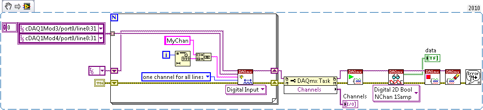
Approach: create a single task, containing two virtual channels (MyChan0 and MyChan1). MyChan0 contains cDAQ1Mod3/port0 / line0:31 and MyChan1 contains cDAQ1Mod4/port0 / line0:31. Digital 2D Bool NChan 1Samp read VI returns a 2 x 32 table of Boolean. To flatten it into an array of 64 elements D 1, you must use the table to reshape or some other method.
The task of DAQmx > ownership of channels is here to show that there are two virtual channels named MyChan0 and MyChan1. Also, I used a loop for to show that you don't have to encode multiple calls to DAQmx Create Channel. The constant "a channel for all lines" is redundant because it is the default value.
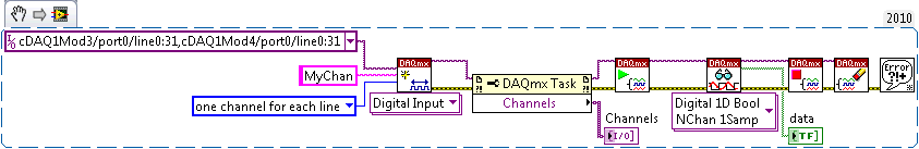
B approach: create a single task, containing 64 virtual channels (MyChan0 through MyChan63). This example uses the constant 'a channel for each line', which is not the default. MyChan0 contains port0/cDAQ1Mod3/$line0, MyChan1 contains cDAQ1Mod3/port0/line1, etc.. Digital 1 d 1Samp Bool NChan read VI returns an array of 64 D 1 of Boolean elements. If you have used the Digital 2D Bool NChan 1Samp VI instead, you would get a 64 x 1 matrix, there are 64 virtual channels with 1 line of each.
Brad
-
I created a labview project and uses a controller RT cRIO-9024 with chassis cRIO-9118. I assigned the NI9474 to 5 slots and the NI9425 to the 3 remaining slots. Now, I need to change the NI9474 to a NI9478. When I try to add a new module of the C series that nothing happens? I tried to remove the project from the NI9474 and I can not yet add a new module of the C series. Can someone tell me what I am doing wrong? Thank you
You only have 1 of each module in your chassis? If so, why did you add the modules to multiple slots? I do not think that it will allow you to add a module if all 8 locations have modules assigned to them - you will probably need to remove the NI9474 and then add the NI9478. If you rename the module/signals, it should not affect your FPGA code.
-
CAN the c series modules and drivers XNET and Ethernet expansion chassis cRIO compatibility issues
Hello
I encountered a problem with my current setup which was not picked up by the tool advise cRIO or by the engineer of applications OR that we used to check our configuration before starting the project. It turns out that the NI 9853 CAN modules require a XNET driver that is not compatible with the NI 9149 expansion chassis.
We currently have a system with a cRIO NI 9068 with general IO and some CAN controller and CAN open modules in a carrycot and an Ethernet NI9149 with more general IO expansion chassis and more CAN and CAN open an another pod remote modules and all of this should work under water, so I can not move the modules of the expansion chassis to the chassis controller without a lot of overhaul of the system and equip and a team of angry engineers and technicians.
I have developed the FPGA code for the 9068 OR and have CAN and CAN open networks works with happiness. Then I tried to copy the same FPGA code on the expansion chassis and it compiles, but when I try to launch it I get the error-63184 code. After long calls OR support, and tries to install the missing drivers on the expansion chassis, we discovered that XNET is not compatible with this chassis.
Can anyone suggest the best course of action? Is there an expansion chassis Ethernet that will support XNET? I have here no information online about this compatibility issue that I can't find?
I'll be communication with DIRECTLY, but from previous experience of the "odd" questions, I know the community often hold the key. Any suggestions gratefully received.
Thank you, Ed
It's official. CAN open modules are not compatible with the expansion chassis. I have them moved to RIO and will get the upgraded pods.
Thank you
Ed
-
in a clear stamp series Module Touch Panel
I use LabVIEW Touch Panel Module make an app on a touch device with Windows CE 5.0. Now, I want to use RS232 touch panel devices to read and write. I use Serial compatibility VIs.It is useful, but it does not offer how to clear buffer rs232, as empty a buffer of e/s in visa. I want to get your help, tell me how clear the rs232 buffer, use that VIs.or how to change Serial compatibility screws for this function. Thank you my dear friend.
What buffer you want to erase? Transmit or receive?
Usually transmit didn't need compensation because anything in it usually gets sent immediately. I rarely need to clear the receive buffer. But an easy way to delete it just to read all the bytes in there and just nothing to do with the data.
-
FPGA error: failed to create the C Series module
I use sbRIO 9631 with LabVIEW 2012, as well as the FPGA 2012 module. Everything worked fine until yesterday, I got this error when creating a new FPGA project.
«LabVIEW FPGA: an error has occurred loading the VI on the FPGA device.» Check that the target is connected and powered and that the target resource is configured correctly.After ignoring this error, I can create any VI in the FPGA target, compile it and it works but can not do anything with host one. MAX configurations show so no error.
I have attached snapshots for convenience.Note: This sbRIO came with a DVD of LabVIEW 8.6 and similarly associated modules version. I had been using this version for a year. Then I got LabVIEW 2012 with the last modules and now facing this error.
Hi NapDynamite,
You should not need to uninstall your previous version of LabVIEW for the development of your PC.
You can see what version of NOR-RIO you have installed on your sbRIO? You can view it by selecting the sbRIO under "Remote Systems" of MAX, and then by selecting the category of software. You may need to update the version of NOR-RIO that is installed on the sbRIO.
You can try this first?
Kind regards
-
How can I configure an entrance series module?
I suspect that it is a very simple question, but being a novice, I need help. I have RS-232 data strings that look like this:
I-00255 - 027.7 - 00.1 003.9 + 0.00 + 0.45 - 0.88 + 0.00-0,03 - 1, 00 - 41.4 + 00.2 + 00.2 - 000.0
I 00255 - 031.3 - 00.1 003.9 + 0.00 + 0, 50 - 0.85 + 0.00-0, 02 - 0.99 - 23,3 + 00.3 + 00.1 - 000.0
I 00255 - 033.8 - 00.1 003.9 + 0.00 + 0.55 - 0.83 + 0.00-0,01-0.99-05.6-00.0-00.1-000.0
I 00256 - 034.9 - 00.1 003.9 + 0.00 + 0.58 - 0.81 + 0.00 0.01 - 1, 00 - 00.7 + 00.0 + 00.1 - 000.0
I 00256 - 035.1 - 003.9 - 0.00 + 0.58-0,82 00.1 + 0.00-0,01-1,01-11,7 + 00.1 - 00.1 - 000.0
I 00256 - 035.7 - 00.1 003.9 + 0.00 + 0.59 - 0.80 + 0.00 + 0.03 - 0.99 + 23, 9 - 00.1 + 00.1 - 000.0How to set up the 14 channls to an RS232 input module to enter these data? Make this "measurement data format" I need to use for each channel?
Thanks in advance.
Mike
First of all, a serial connection has a single "input". I think that what you ask, is to know how to analyze the unique string read 14 separate channels. Second, you have not specified the language you use. In LabVIEW, you would use the VISA Office to set up and read the data to the serial port. There are some examples that you can watch. For parsing the string, you can use something like string of worksheet to the table with a space as the delimiter.
-
Relay control using cRIO LabVIEW and the NI 9472 c series module
Hi all
I try to get my program to run so far without success, and need help.
I use the compact rio with the program on labVIEW and the NI 9472 digital output module. I enclose my VI.
Basically, it's a test program to run an algorithm at a time. If I use a solid state format to get a time warp that dictates, time of execution of the algorithm. The operation by default, I put is for when the time channel produced a fake.
Question 1: The problem I have is that even if the time string is true, as it does not run. It remains in State sending false so only of false signals to my relay (which is represented by the round LED - relay switch a solenoid on and outside).
Question 2: If I can get 1 problem solved, the next step I have will be executing the same algorithm, but for more than a State of time. For example. "06:00" run algorithm. I want this algorithm to keep running as long as he sends signals REAL (which means the solenoid valve remains open until a WRONG signal). Then he will run again to say '08:00 ', execute the algorithm as long as he sends signals REAL and so on...
In summary -.
-I want to order a relay (which controls a solenoid)
-L' use of components listed above
-With the help of semiconductor in labVIEW (VI attached)
-At different times, the execution of the algorithm UNTIL sends the WRONG signal and then return to the default state, which means that his waiting until the time channel product TRUE.
Any help would be appreciated.
Kind regards
William
something like that...
-
Nexus 7009 does not show the N7K-F248XP-25 modules ethernet ports n sh run
Hello world
I have a question...
I'm going to install two Nexus 7009 with N7K-F248XP-25 three modules on each of them, I plan to create 3 VDC, but initial configuration, the system does not display the Ethernet ports of these modules, even with the inventory of show and show module that I can see that the modules are recognized and its status is OK. Is there something I need to do before you start to configure these modules...? allow some feature or the license in order to see the ports with show running CLI...?
You can activate the F1, F2, M1, M1XL, and M2XL series modules. There is no restriction on the type of mixture allowed for the order of module-type system. Control module-type system allows a mixture of F1, F2, M1, M1XL and M2XL series of modules in the VDC.
Note
 The module-type limit-resource command handles the restrictions on the types of module that can be mixed in the VDC.
Note
Use the f2 type module-system command to allow the F2E series modules in a VDC. The ports of F2 and F2E series modules can be distributed as all other ports.Note
The modules that you do not select must not be powered on after you configure this feature and enter Yes. An error message will force you to manually disable these modules before you continue. You will avoid significant disruptions and problems of service within a VDC.No form of this command resets the configuration mode to enable all modules.
hope this helps
-
Cisco Nexus 1000V Virtual Switch Module investment series in the Cisco Unified Computing System
Hi all
I read an article by Cisco entitled "Best practices in Deploying Cisco Nexus 1000V Switches Cisco UCS B and C Series series Cisco UCS Manager servers" http://www.cisco.com/en/US/prod/collateral/switches/ps9441/ps9902/white_paper_c11-558242.htmlA lot of excellent information, but the section that intrigues me, has to do with the implementation of module of the VSM in the UCS. The article lists 4 options in order of preference, but does not provide details or the reasons underlying the recommendations. The options are the following:
============================================================================================================================================================
Option 1: VSM external to the Cisco Unified Computing System on the Cisco Nexus 1010In this scenario, the virtual environment management operations is accomplished in a method identical to existing environments not virtualized. With multiple instances on the Nexus 1010 VSM, multiple vCenter data centers can be supported.
============================================================================================================================================================Option 2: VSM outside the Cisco Unified Computing System on the Cisco Nexus 1000V series MEC
This model allows to centralize the management of virtual infrastructure, and proved to be very stable...
============================================================================================================================================================Option 3: VSM Outside the Cisco Unified Computing System on the VMware vSwitch
This model allows to isolate managed devices, and it migrates to the model of the device of the unit of Services virtual Cisco Nexus 1010. A possible concern here is the management and the operational model of the network between the MSM and VEM devices links.
============================================================================================================================================================Option 4: VSM Inside the Cisco Unified Computing System on the VMware vSwitch
This model was also stable in test deployments. A possible concern here is the management and the operational model of the network links between the MSM and VEM devices and switching infrastructure have doubles in your Cisco Unified Computing System.
============================================================================================================================================================As a beginner for both 100V Nexus and UCS, I hope someone can help me understand the configuration of these options and equally important to provide a more detailed explanation of each of the options and the resoning behind preferences (pro advantages and disadvantages).
Thank you
PradeepNo, they are different products. vASA will be a virtual version of our ASA device.
ASA is a complete recommended firewall.
-
How to choose the time of conversion on a module in the series C NI 9207?
I have a NI 9207 C series module that is currently attached to a cDAQ chassis 9181 (it moves to a cRIO soon, however). The manual States that there are two modes of conversion time, high resolution and high speed. Apparently, the default value of the plant's mode high resolution since my maximum acquisition rate is less 20 Hz single channel. I have read the manual to research how to define it, but the manual does not cover the intangible aspects of the implementation. I think that there should be a way to do in the two MAX and LabVIEW. It is enough to affect the rate of acquisition you want something that is supported only by the mode high speed does not switch automatically, because LabVIEW generates an error when you do this (frequency of acquisition application exceeds the maximum acquisition rate).
Can someone tell me how do to it. I would like to know how to do it in LabVIEW and Max (if supported).
Thanks in advance for any help you can provide!
Well, I guess I just need to do some more digging and DIY.
I didn't understand how to proceed to the MAX, but in LabVIEW, you can use a property DAQmx Channel node. I don't check the channel palette because I thought that it was configured per device / channel... I was looking on the property DAQmx Device node.
Thus, in case anyone else is looking for this answer to the LabVIEW environment, set this value using one of THE. ADCTimingMode on a node property DAQmx input channel.
-
None of the DIO Modules of series C are configurable as inputs of counters?
Hello
I work with the Compact RIO 9022 with 9104 chassis. with the work that I work here, I have the need for a large number of counters, is possible to configure the entries on a map NI 9426 DI be counters? and how would I go to do this? If this is not the case, the C Series modules do not support counters for the RIO?
Hello
Thanks for the quick reply, can't find the foundations of FPGA-> counters.
Would you be able to sent me the URL
Thank you
Kevin
-
Why do I get error-65581 when you try to use a cRIO 9024 and modules c series
I am trying to send a digital high on a 9401 c series module DIO0 and I get the following error every time.
65581 error occurred in shared Variable to send true value Out.vi
NMAYO,
Depending on your project can you right click on the chassis in the cRIO and make sure that it is set to the Mode Scan mode and not FPGA? In addition, in the solution of measurement and Automation Explorer, you can check the cRIO and check that it has the Support of Scan Engine is installed. The tutorial below shows how to reformat a cRIO and install the software on this subject, the subsequent steps in the software allow you to check your cRIO.
-
Using the C-series SCTL DIO module with slower than the top level [FPGA] clock
Hey all,.
I'm running online research on a problem that I have a lot of success.
I have a chassis with integrated FPGA, top-level 9030 clock 40 MHz. I have a NOR-9401 DIO C Series module plugged and the value that will be managed by the FPGA target. I need to count some linear encoders to exactly 10 MHz, no more, no less. They are periods and gives a result of such kind that if I oversample or underestimate, I get garbage.
If I create a SCTL and assign a source of synchronization derived from 10 MHz, I get an error code generation who:
"Node read e/s for DIO3 FPGA is used in a clock domain that it does not support. Areas of clock supported include: the clock of higher and clocks that have a rate that is a multiple of 40 MHz, for example 40 MHz, 80 MHz, 120 MHz and so on. »
I tried several ways to work around this problem; First I tried just using a while loop with a loop set to 4 is ticking timer, but it then takes 9 clock cycles to perform the count for a reason any (although this code may compile in the SCTL without any problem). I then tried to use the SCTL with a constant of 'true' AS a hack for a 'timed sequence' framework-related, and that certainly has not worked.
Are there any strategies or techniques, or settings somewhere to work around this limitation on the AID I need to taste exactly 10 MHz? I'd like to do this quickly in the software and get this rolling as soon as POSSIBLE.
An image of the relevant section of the code is attached, I'm happy to provide you more things on request.
Thank you very much!
Maia Bageant
Thanks for the reply! The problem ended up being a hardware problem based on how coders were connected. Now that I've fixed it, they're perfectly happy are oversampled.
I guess my question is always legitimate to other applications, but not necessary for encoders a.
-
Hello
I - labview 2011,-LVFPGA in real time-, - NIRIO 4.0, cRIO - mdk 2.0 and cRIO module - support 4.0.1...
I work in the construction of a new module of m... first of all, I want to control the slots on the frame... So, I run, software part of that
application ==> http://zone.ni.com/devzone/cda/tut/p/id/7868
and it works... I see the signals on my oscilloscope...The problem is that I couldn't find a way to add the generic module to my own FPGA project...
I also study the sample application by giving this link ==> http://zone.ni.com/devzone/cda/tut/p/id/4539
and you see it add the cRIO-generic module in embedded project.Here's my way
* I m creating an empty project and add cRIO-9004 by > right click (Project) > New > target and devices > time real compactRIO > cRIO-9004
* and then, good click target FPGA (cRIO-9103) > New > C Series Modules > new target or device > C Series Modulebut I couldn't see the module "generic"...
What I m missing?
I had the same problem. Arise in 2009, but not 2011. See this:
I added the line "cRIO_FavoriteBrand = generic ' in the ini file." He now appears less 2011.
Maybe you are looking for
-
Satellite U - restarts and restarts so that the installer of Windows 7
I just bought my new laptop Toshiba from Harvey Norman. When I try to put in place, it just restarts again and again and I can't do anything to stop it. It says installation configuration. Harvey Norman is trying to tell me that it will take hours fo
-
How can I activate Windows 2003 STD SP1 OEM Dell on VMware?
I'm trying to old Dell again P2V VMware. P2V seems OK, but I had a problem during the activation. When I enter the correct product key, Windows says that the key is unauthorized. Of course, I know the license OEM is valid in the old Dell, but I have
-
How can I change the keypad to display in order of calculator, with 7, 8 and 9 of the first row?
I am a user of 10 keys and the numeric keypad is configured as a phone, not a calculator. No way to change this? I have windows 8.1 on my acer tablet. Thank you.
-
Messages from Lenovo Solutions Center
I just reinstalled Lenovo Solutions Center (3.2.002) - wow! Nothing like the previous version and would seem to be a lot less useful. After the execution of the first analysis equipment, all is well except for two topics that are unexplained. The P
-
Serial number of the power supply in UCS - C
Hi, anyone knows how can I get the serial numbers of the power supply in a UCS - C? Is there any command to get it? Thank you very much.